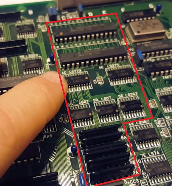
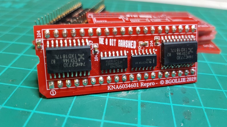
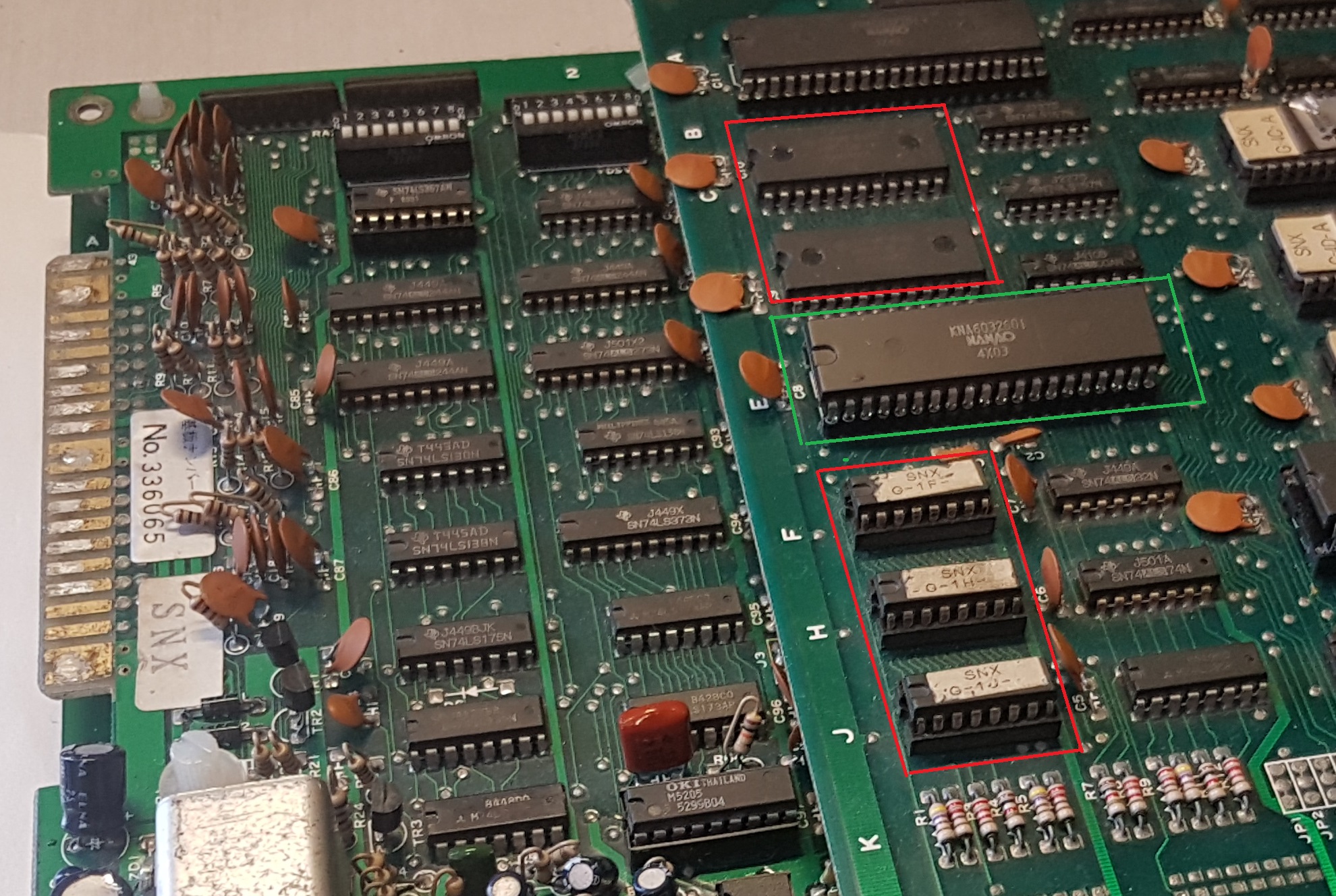
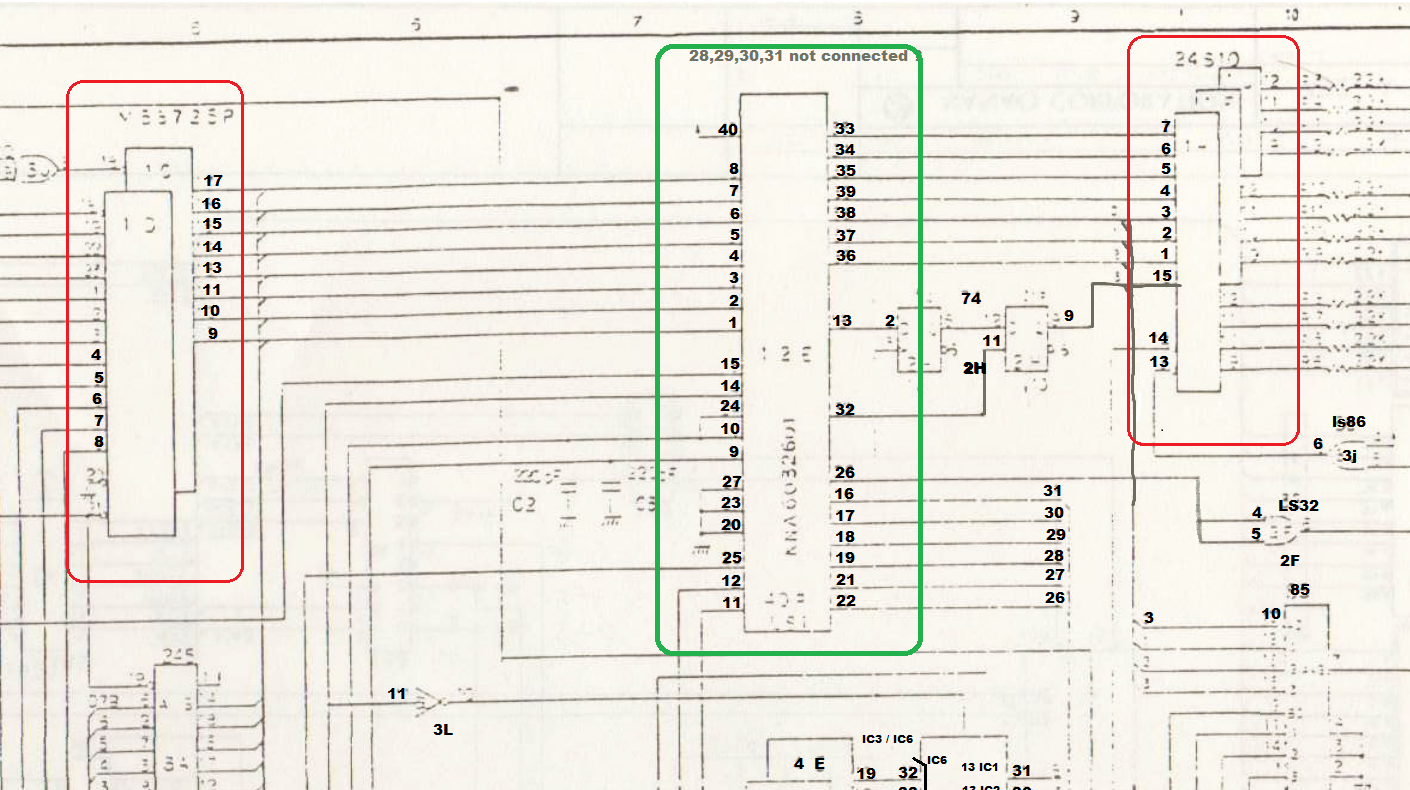
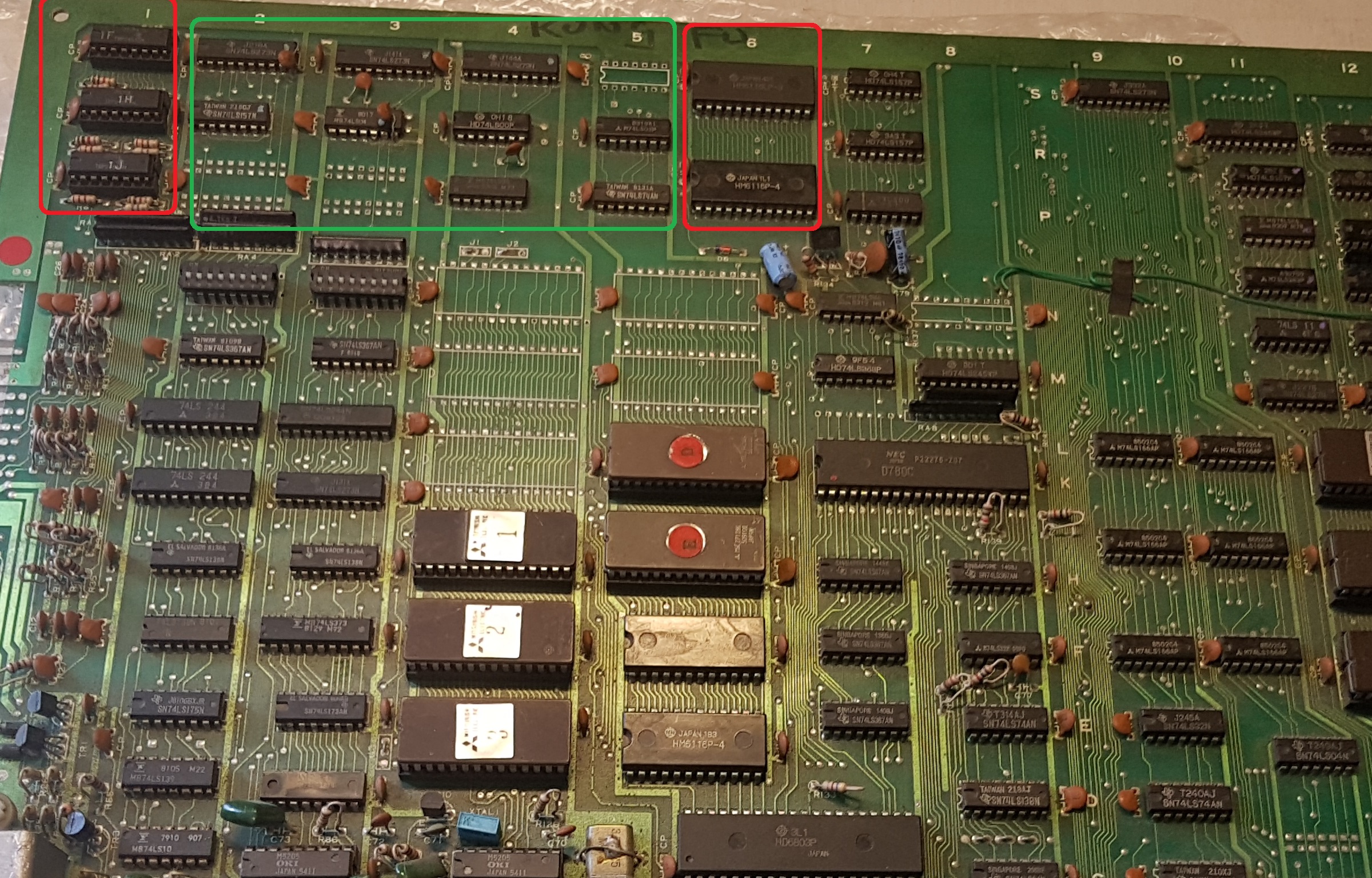
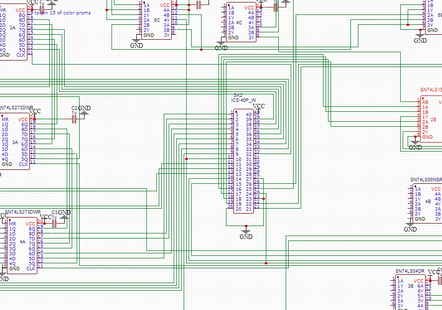
It’s a 40 pin custom IC on the TOP board of the kung Fu Master stack, sitting at E1 & E2 between two rams and the colour proms
This most likely deals one deals with the final image processing, like layer priorities, just before outputting data into the colour proms
I used a bootleg to see how this one was reverse engineered by bootlegers at the time and identified and area between the rams and the colour proms.
Tracing multimeter confirmed those 9 LSxx ICs were indeed connected to the same ICS as the custom. So I fired up easyEDA and got busy .
A few days later, voila! a working IC and a working board. Not a complicated thing to do, it just takes time to trace back everything .
Huge thanks to Caius for his recent inspiring work on making repros for a lot of these custom ICs and has prompted me to look into the topic and start making my own too. The more the better !
And as usual, for those who prefer the video format :
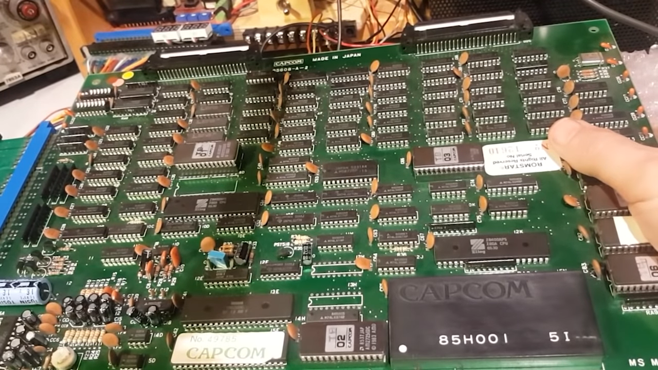
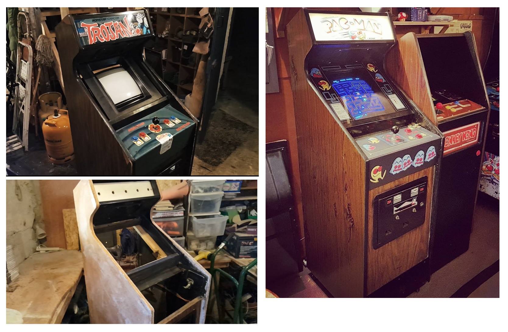
I got this board a few years ago when I got a Pac-Man cabaret cab that had been converted to Trojan.
The whole cab was sold to me as not working so I assumed the board wasn’t booting either I converted the cab back to pacman and put this board aside until this year
So I fired up the board and it booted up just fine. However there was absolutely no sound coming out.
One of the issues with this board is that there aren’t any schematics available for it.
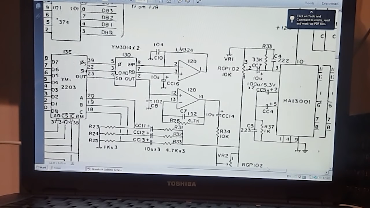
Luckily the sound section is almost identical to Ghost n Goblins.
Since the traces are visible on the board, I drew them for help on the back of the board.
Crude but it helped figure out things a bit.
It’s got that same sound module (85H001) to drive two YM2203 (3 channel sound chip)
The signal is then fed to a YM3014 DAC, and LM324 Op-Amp and a final HA13001 power amplifier.
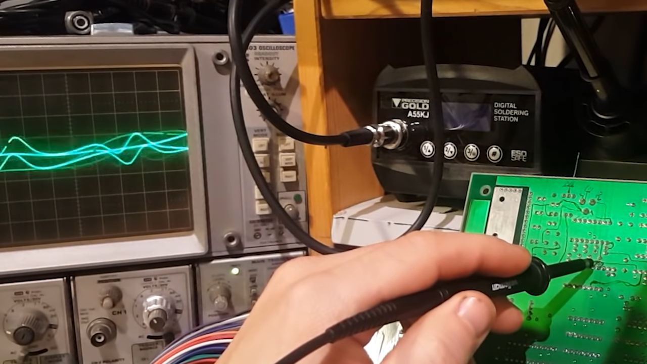
Probing the YM2203, YM3014 , LM324 I can see signal coming out of all these and into the input of the power amplifier .
However there’s nothing coming out of the HA13001 so I’m assuming this is the culprit here.
Removing it, half the legs broke off . No wonder it wasn’t working
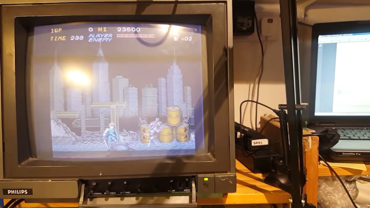
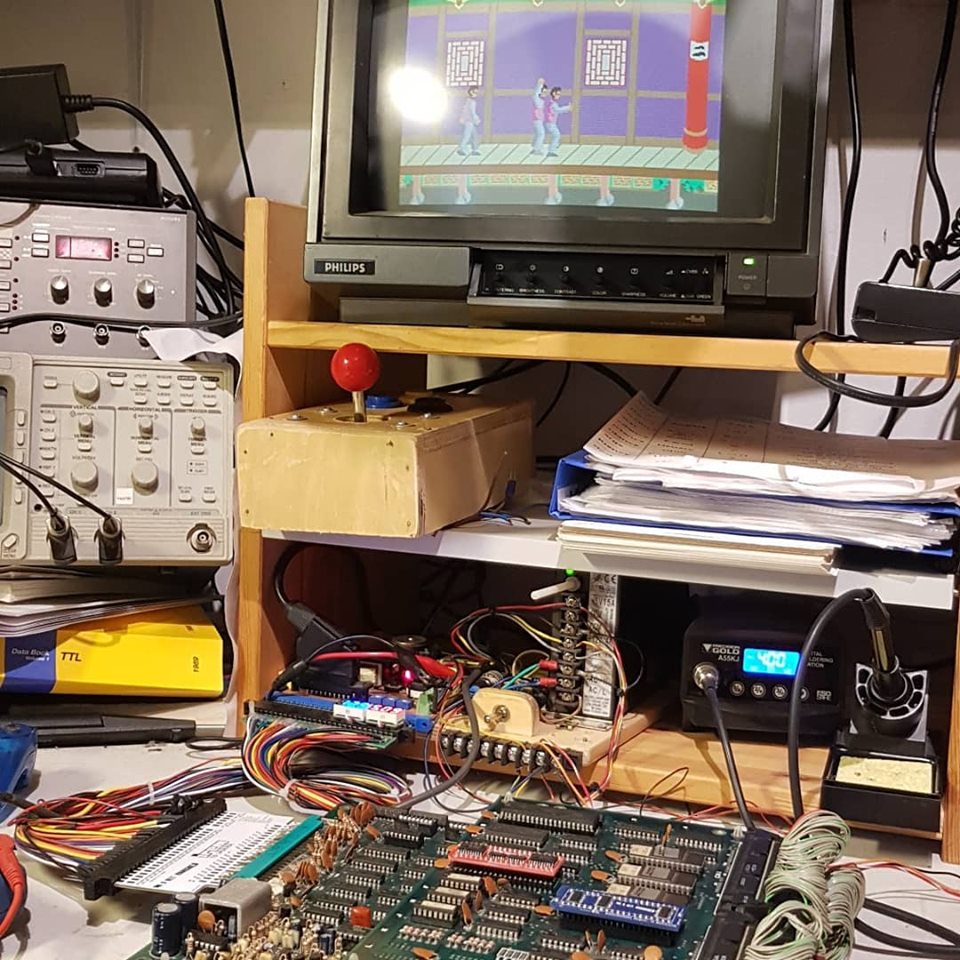
I fitted a new one and the sound came back right away and I was able to enjoy a quick game of Trojan
A quick and easy one but you need these every now and then
And as usual, for those who prefer the video format:
I got this Bombjack Bootleg board a while back when I just couldn’t find any original boards for my cab. I since got an original board for it but this bootleg has been left for repair since then.
It was sold as “graphic & sound issues” without more explanations. Lucky though, these bootlegs are identical to the original boards.
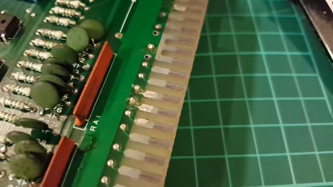
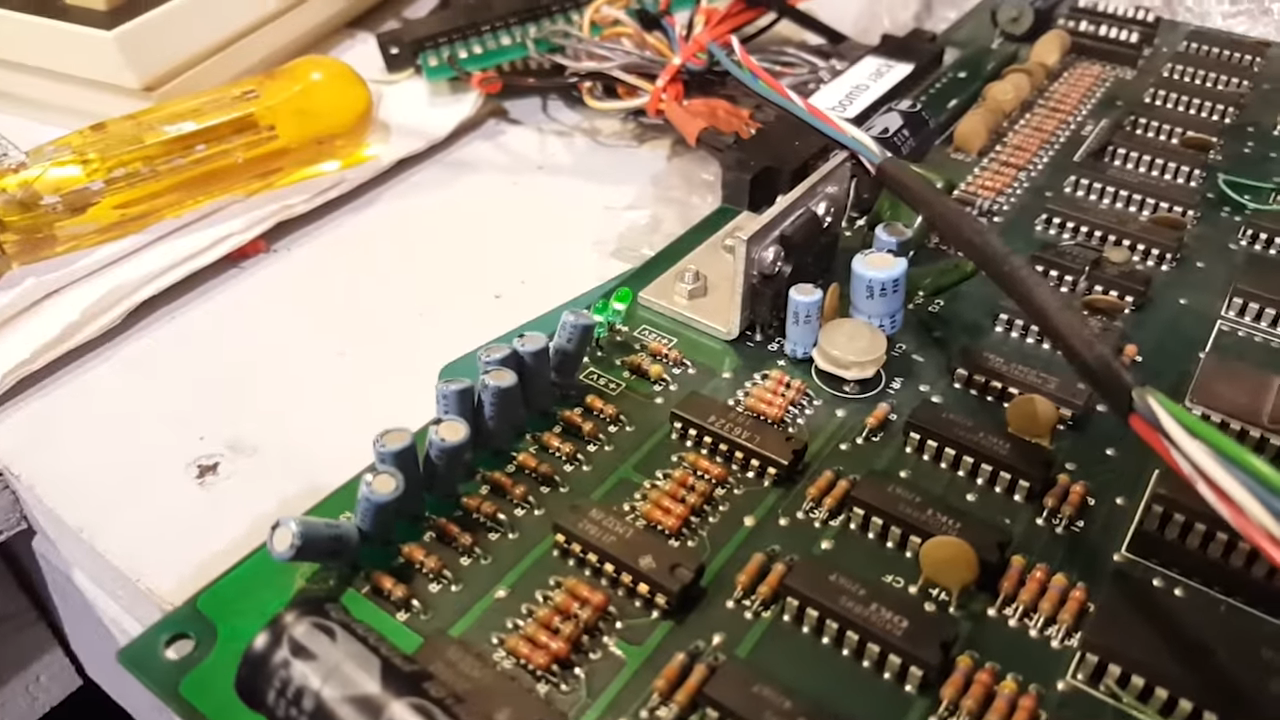
A first visual inspection reveals a few loose & broken filter capacitors and a couple of messy traces near the edge connectors. Hard to say without a magnifier if they’re broken. The caps won’t be an issue for now so let’s focus on the traces
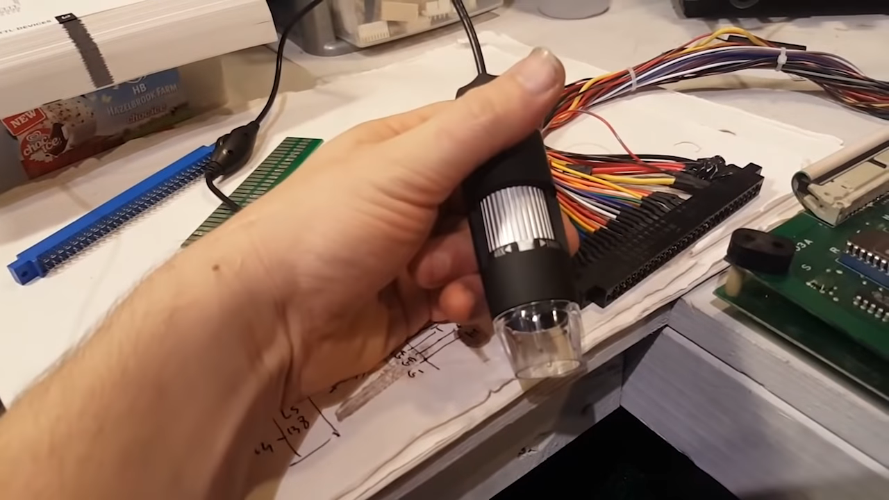
I could do a quick continuity test but as it happens, somebody sent me one of those cheap chinese microscope things. They’re essentially a USB webcam , so this is a good opportunity to give it a test.
Indeed two traces were broken, a quick solder bridge will fix that. Handy little toy that thing!
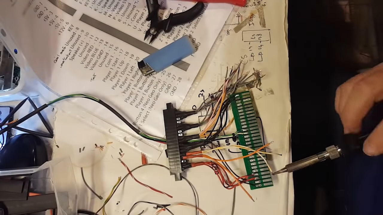
Next, I had to make an adapter since the board didn’t come with one.
On these boards the video signal comes from a separate connector on the far edge of the board. You can already spot there’s an IC missing there too
This might explain the graphic issue.
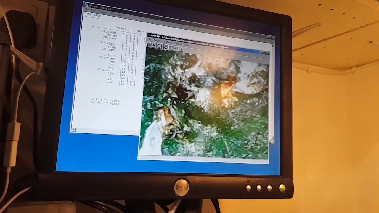
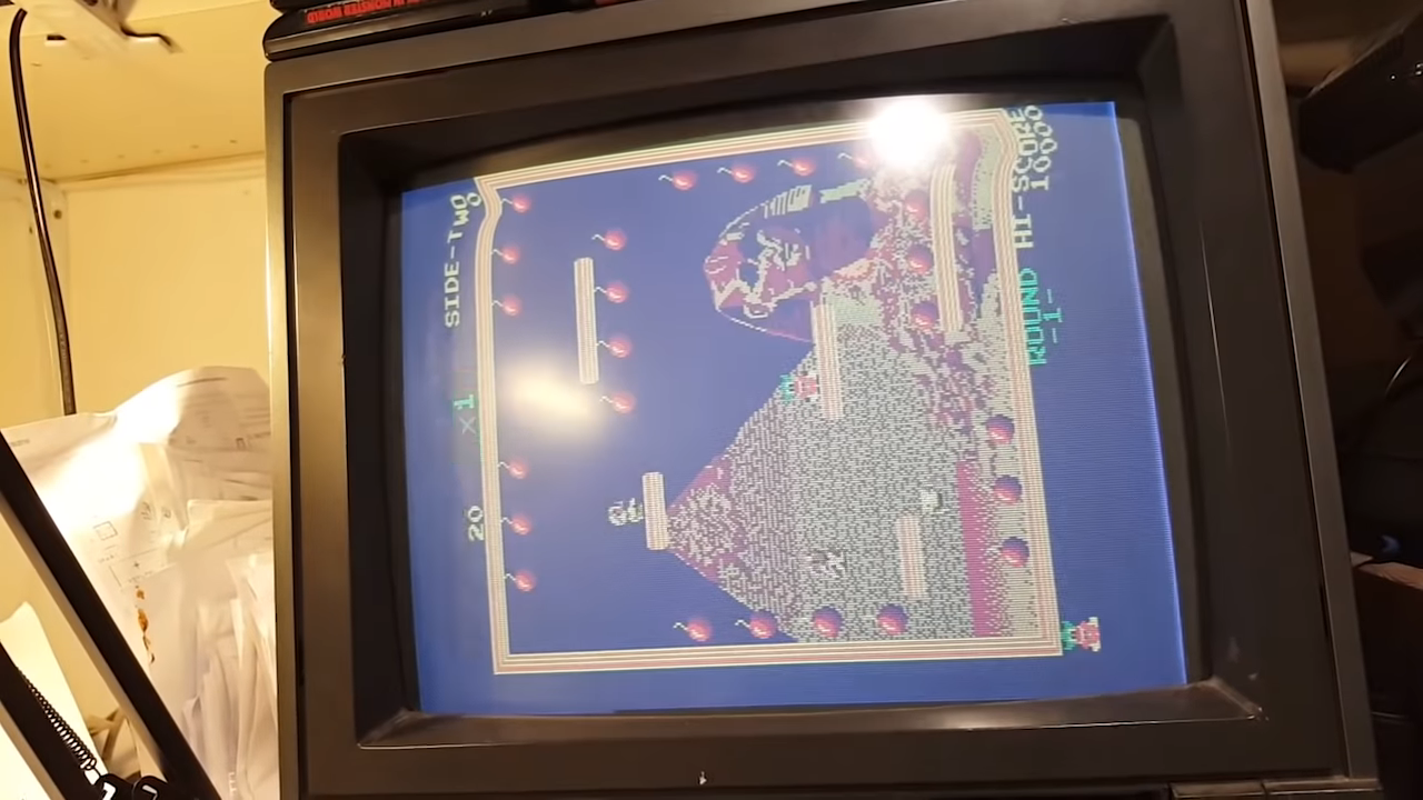
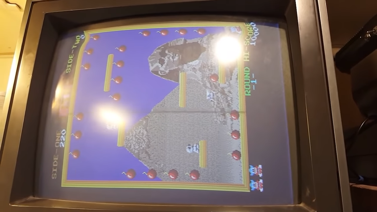
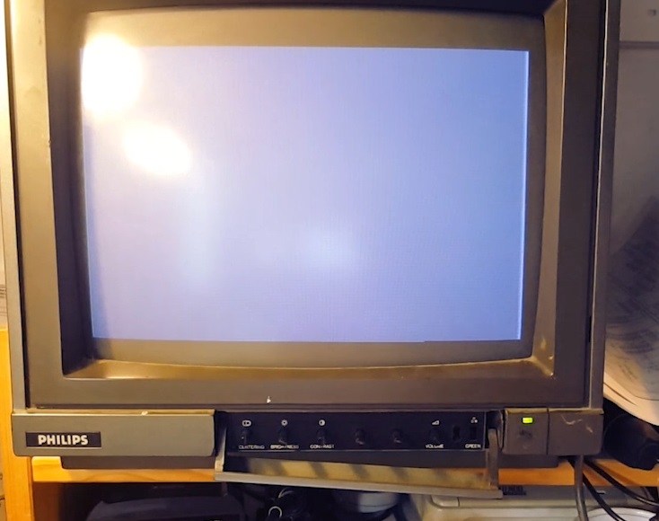
But first let’s finally power the board and check what we get.
So our colors are off, some graphic information is missing. There’s no sound coming from the board either. The wavy effect on top of the screen is an artifact of my monitor being in need of a re-cap so we can ignore this.
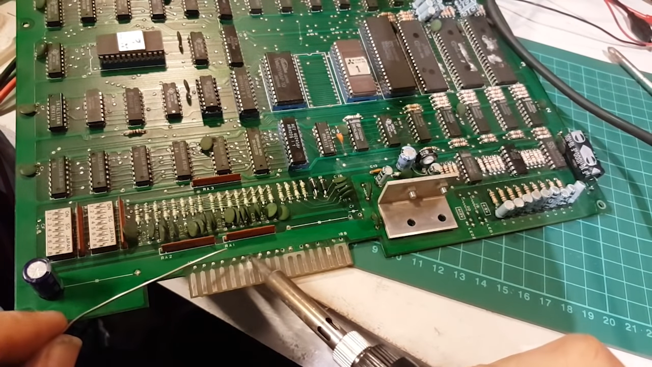
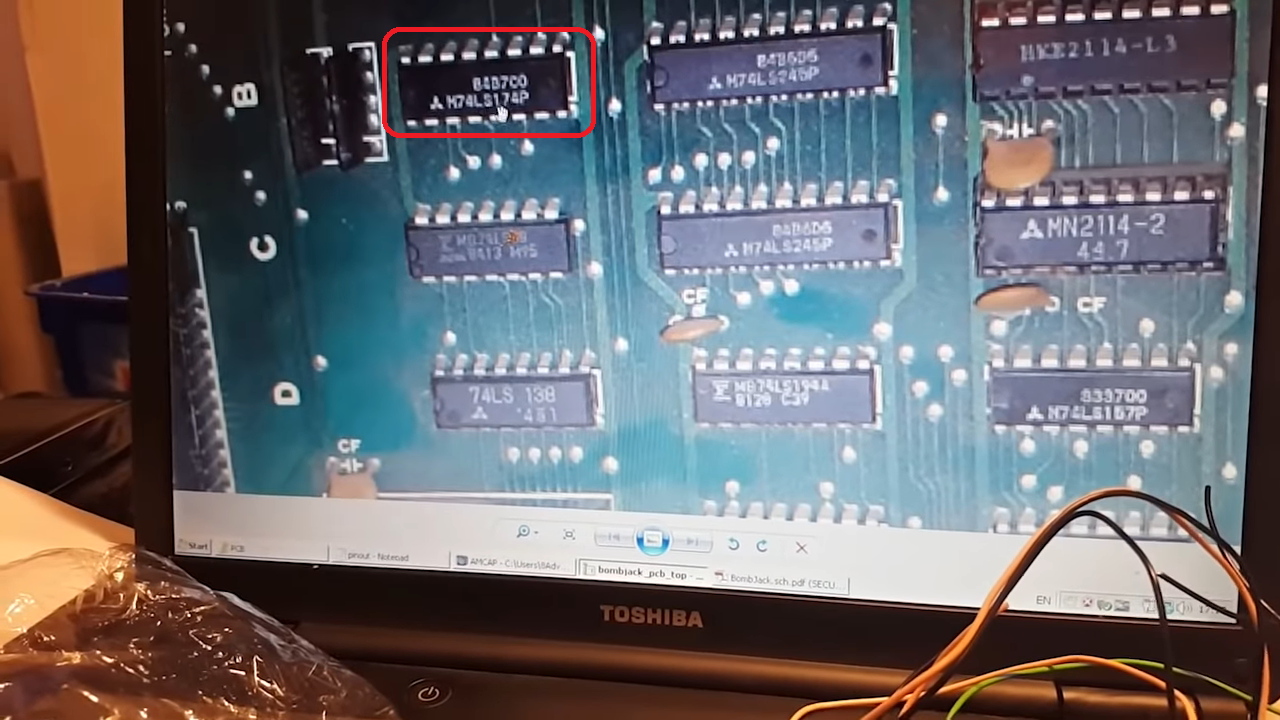
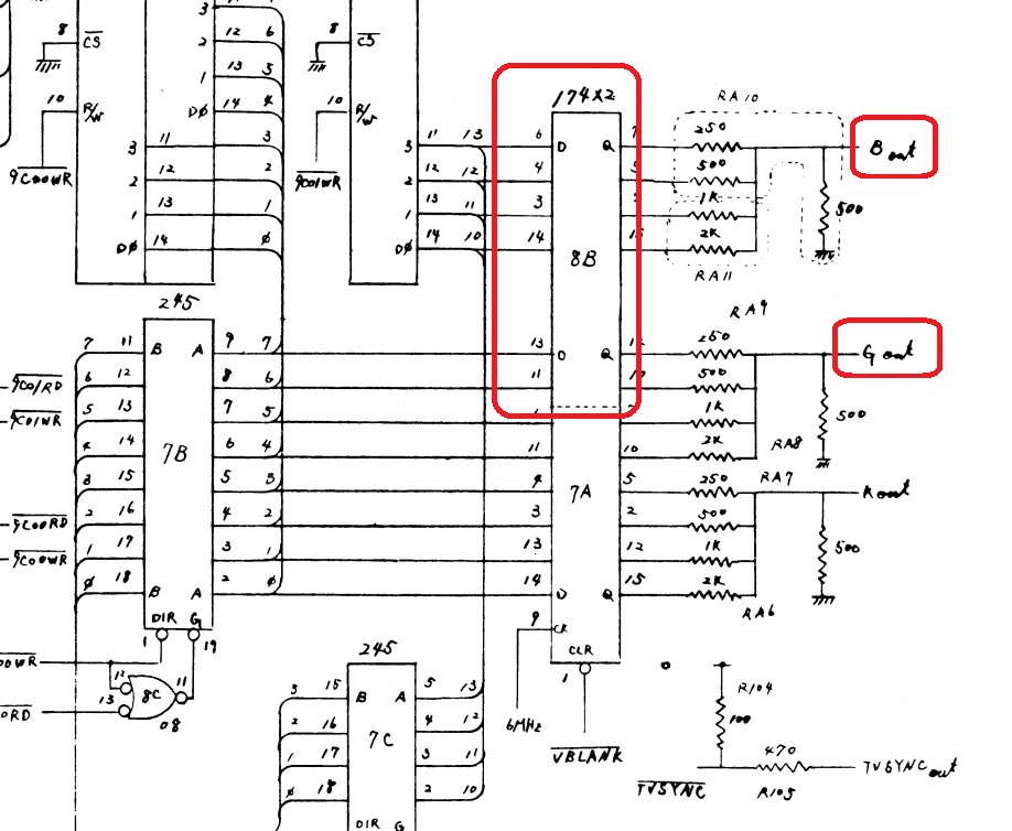
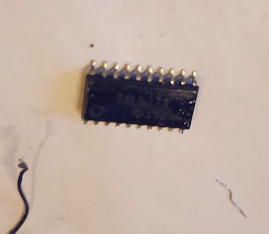
Let’s first take care of that missing IC. Looking at a photo found online, this should be an LS174 flip-flop.
I then checked the schematics and this confirms it as a pair of these is handling the color signals. Our missing IC at 8B handles the blue and part of the green signal.
Let’s drop a fresh one and see if this restores our picture.
Success!!
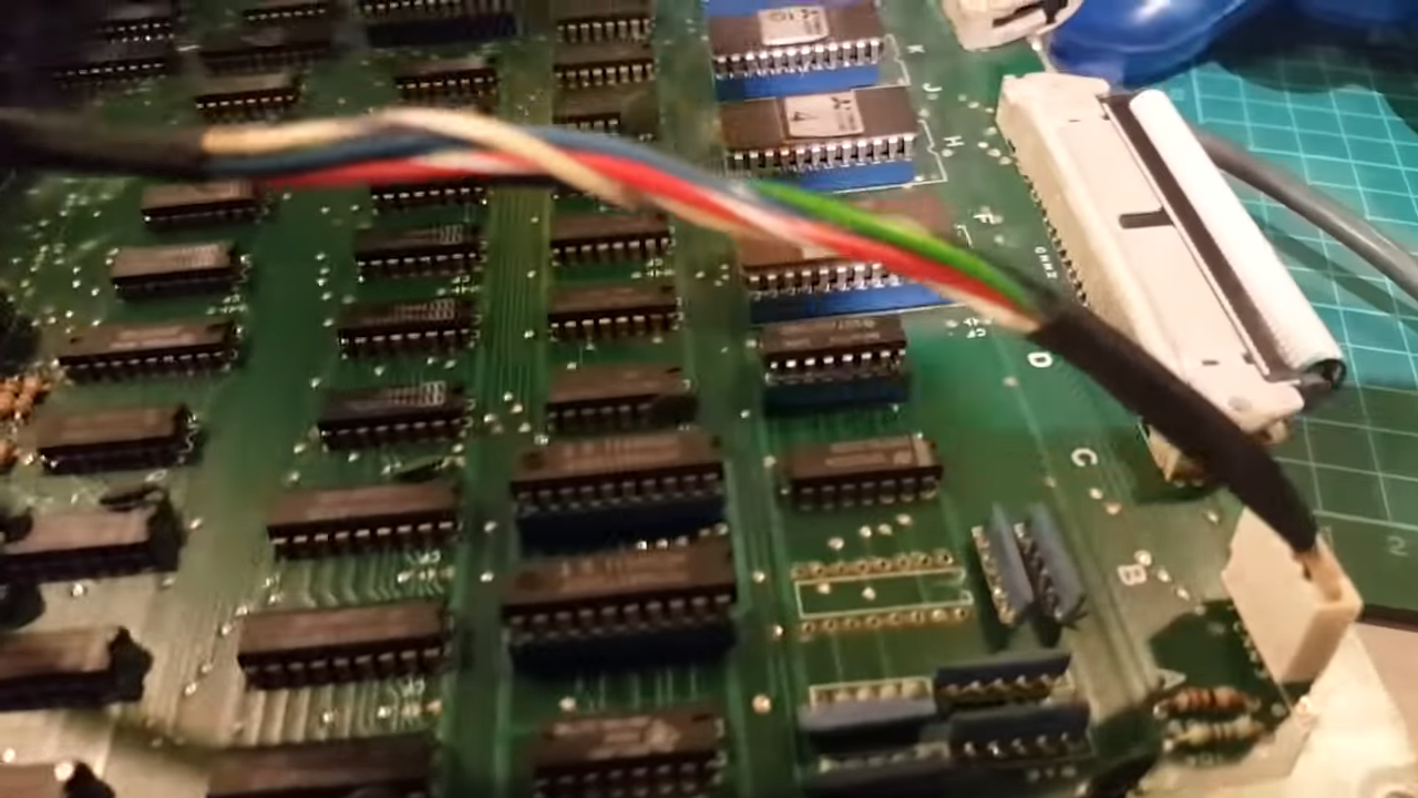
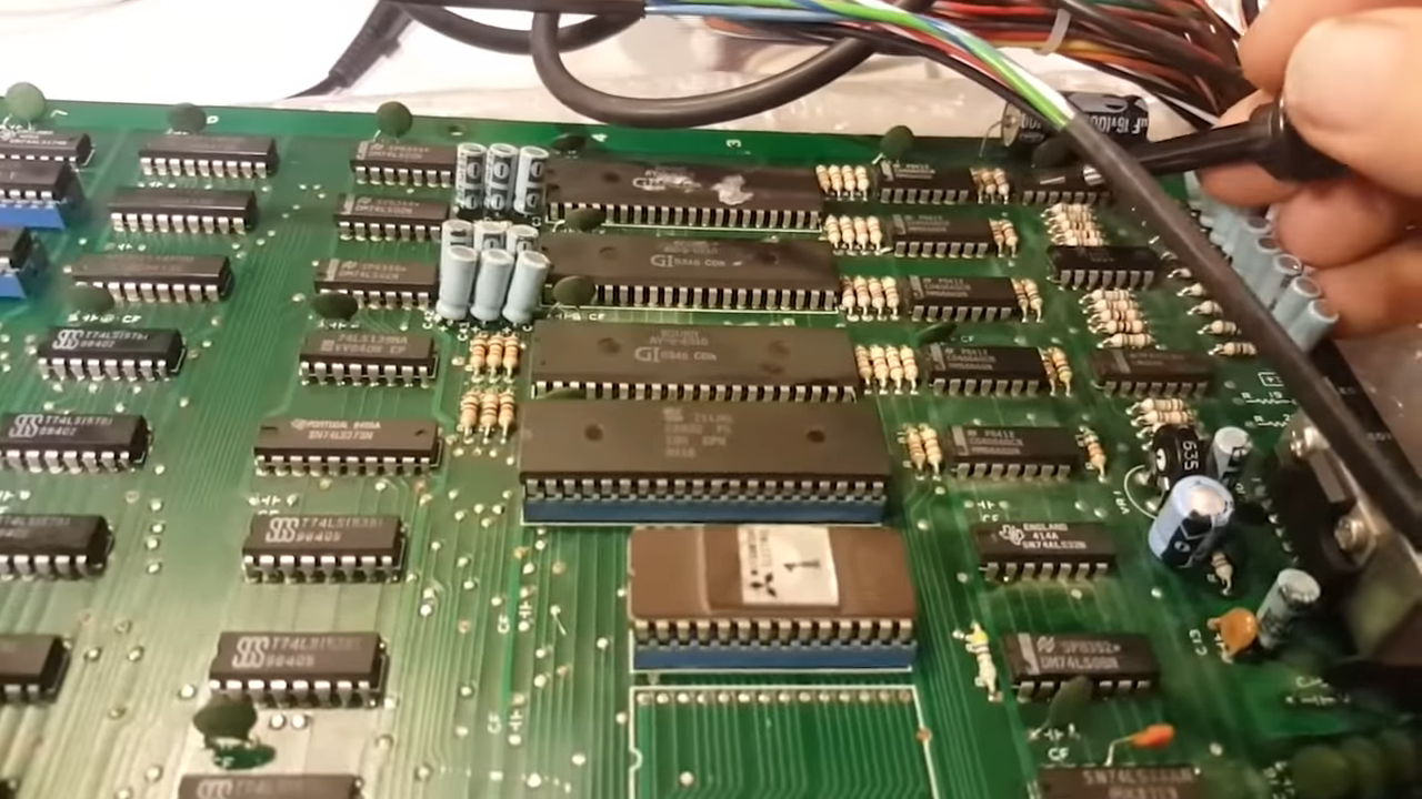
Now to address the sound issue. Probing my way from the amp back I eventually realized I’was not getting any signal. All outputs on the sound ICs (three AY-3-8910) were dead , I suspected the z80 controlling these.
Swapping it with a new working one restored the sound completely board … here’s a photo for proof :
In addition to this I did make a couple of mistake on my adapter, meaning the controls worked incorrectly. I spent some time trying to troubleshoot this till I double checked my adapter. ah well. Another case where having another working set would prove useful.
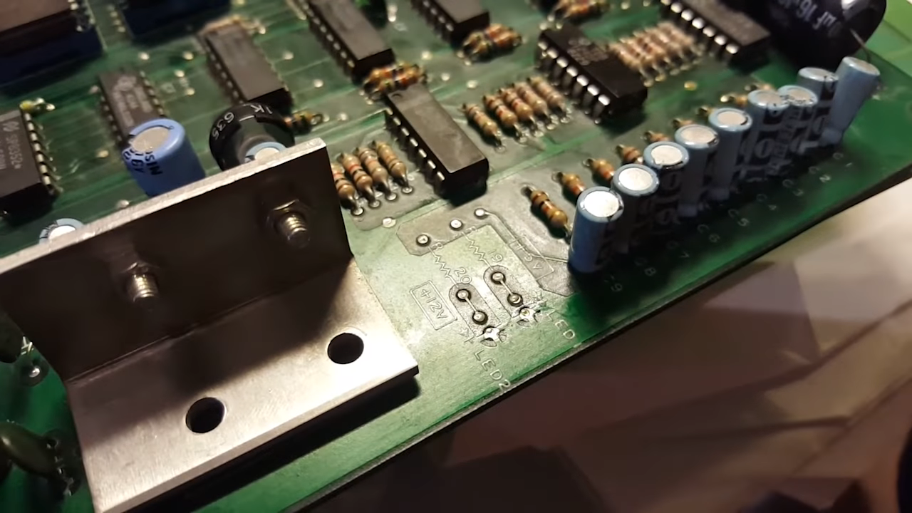
Anyway the board is working fine now, but while I tidied a few loose capacitors around the board I spotted this unpopulated section of the bootleg board:
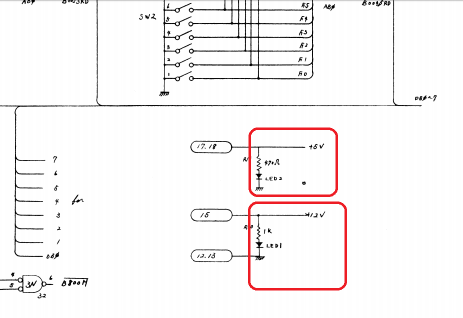
Silk screen and holes for two leds and resistors. Comparing to an original board and checking the schematics, these should be indicators for the 5v and 12v lines.
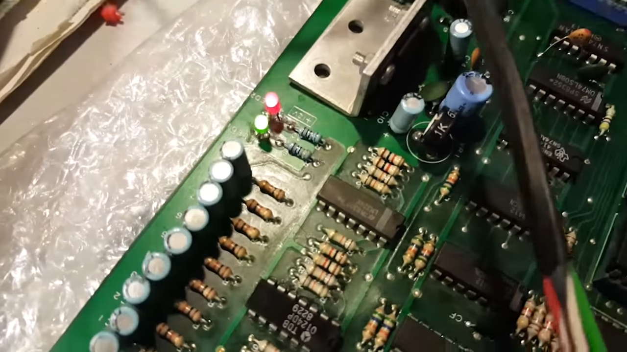
While this is not strictly needed it’s an easy thing to just add them . I went for a green 5V and red for 12V
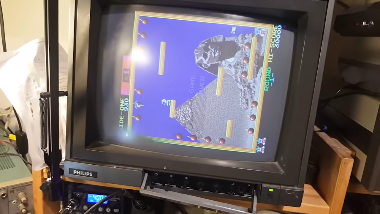
yay . a fully working Bomb Jack bootleg.
And for those preferring the video format:
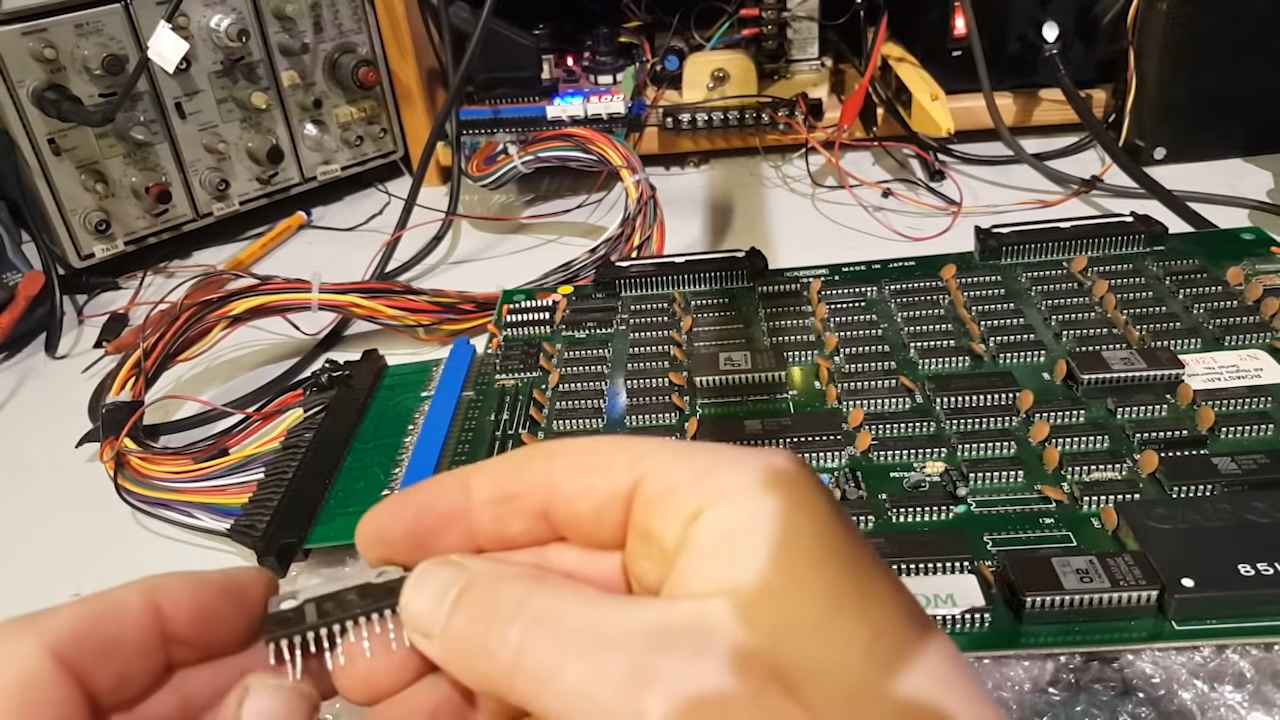
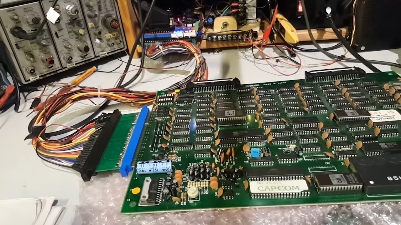
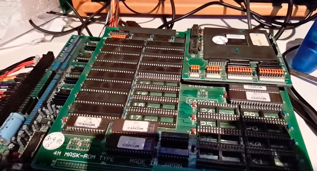
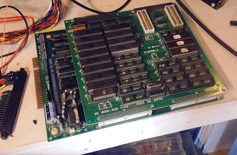
A while back I got my hands on a cheap CPS1 set for Street Fighter 2 CE. The reason it was cheap was that the A board was not working. As we know by now, these A boards are dying quite fast and in some cases the culprit is the Custom CPS-A-01 chip for which there are no know replacements as of yet.
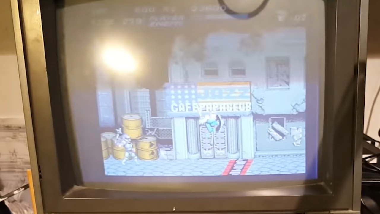
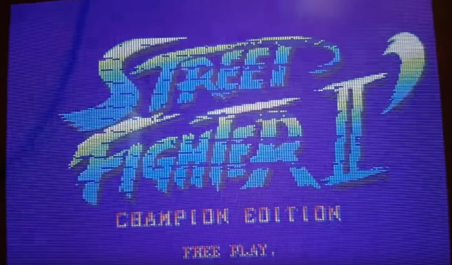
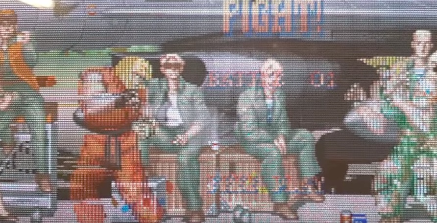
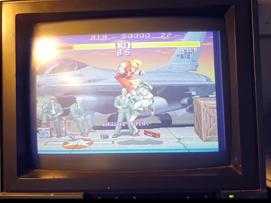
Let’s have a look at what we get on screen first
So it seems we’re only getting half the lines in the sprites and , while it’s not visible on a screenshot, the other half is flickering slowly too.
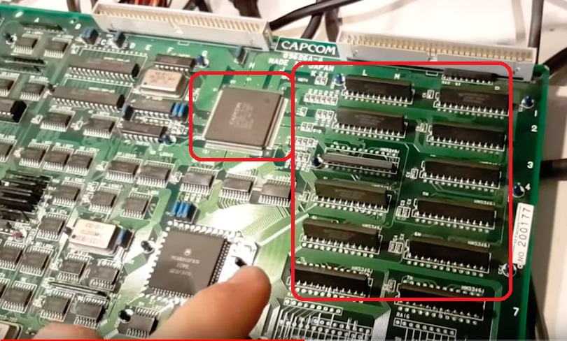
Looking at the schematics we can see the two parallel banks of rams processing each odd/even lines of sprites. These are coming straight out of the CPS-A-01 GPU IC. Let’s check out the DT/OE enable lines or the rams first.
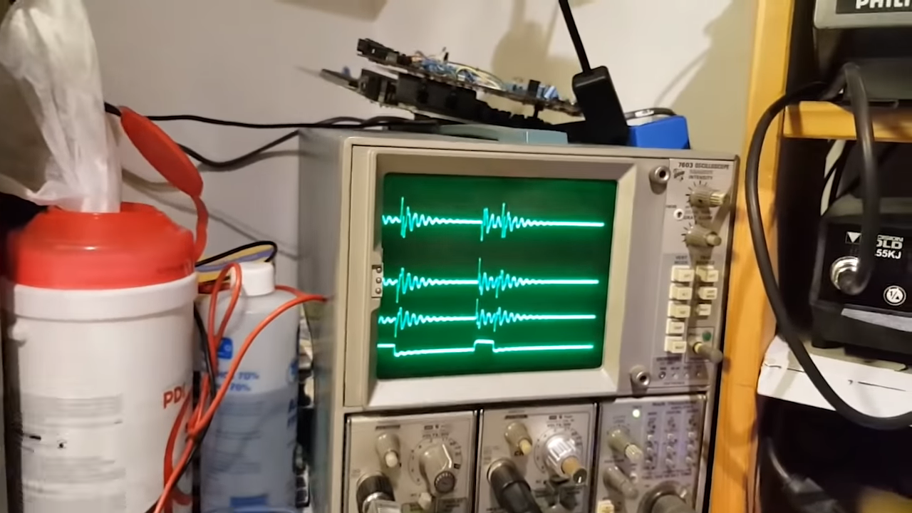
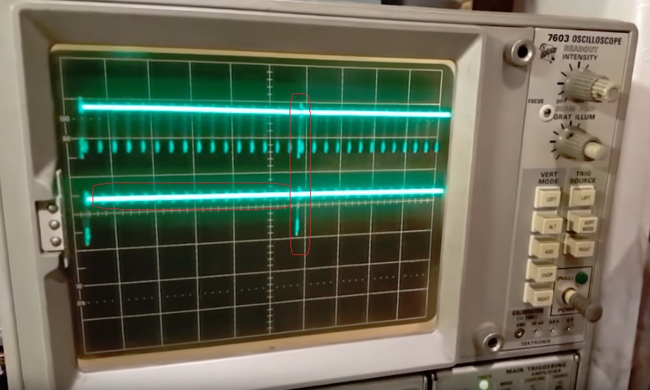
Looking at them in with the scope reveals a couple of issues:
The bottom one is pin 21, and it’s not really toggling apart from that one regular jump, while we can see that the other line is toggling all the time. This is why we’re only seeing half of the sprites: one bank is not being enabled.
The other issue is this jump on both lines which is most likely why the entire sprites flicker regularly.
These are coming from Pin 21 and 47 of the cpsA .
bank A pin 21
bank B pin 47
Tying the enable line of bank B to bank A will restore the sprites but we still have the issue of the flickering sprites… in a nutshell, the CPS-A chip is fried and this A board is toast.
Luckily a viewer of the youtube channel (thanks Kris Ankers!) sent me a spare A & B board.
The board is in unknown working state . Checking the few remaining proms it’s another SF2 CE , not that it makes much difference here as we’re only interested in the A board. Let’s replace the A board on my other stack and fire this up
…nothing. board is dead.
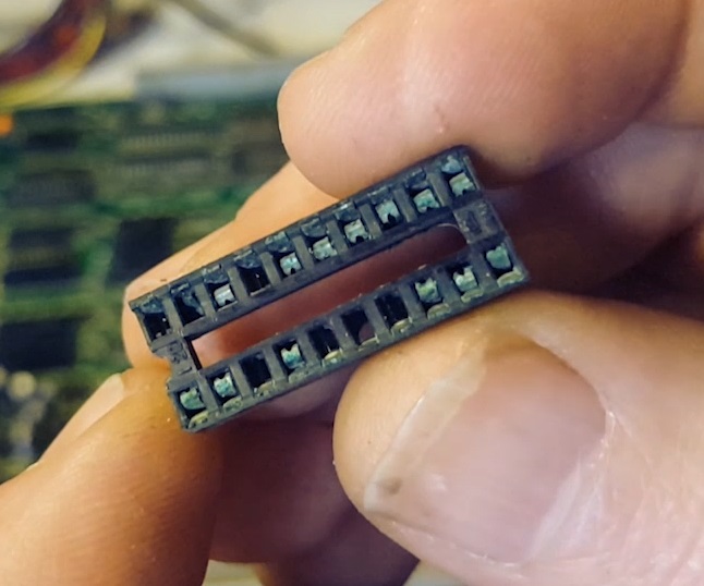
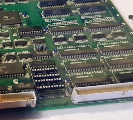
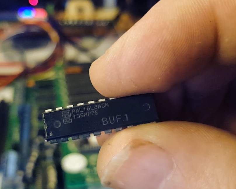
A quick visual inspection reveals a few corroded badly corroded sockets on the BUF1 and ROM1 pals. corroded is an understatement here too since the socket were missing legs that had completely disintegrated.
Let’s put new sockets in place and see what we get.
Still no boot. I took both pals from my other set and dropped them in.
After some more swapping I found that the Rom1 pal is working so it was just the BUF1 pal that needed to be replaced.
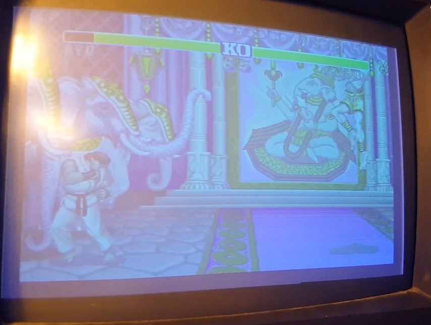
Success!! The board is now booting and playable. Sound is also working fine.
But it seems we’re missing the red color.
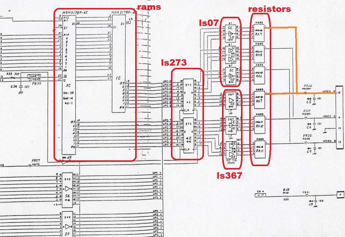
A look at the schematics tells me me which ICs are handling the rgb output. We’ve got two rams outputting to 2 LS273 flip flops. This is then sent through ls07 and ls367 buffers, through resistor arrays before being output to rgb.
The difficulty here is that apart from the legs of the rams and resistor arrays which can be probed from the underside, the other ICs are SMD and hidden by the b board so I am not able to probe the legs. Time for some logical guess work :
Since the pairs of ls07 and ls367 are shared across the colors it’s unlikely one of those has failed or it would affect more than one color (still possible but unlikely)
Two resistor arrays are needed per color. If one had failed, we’d get some red at least but here it’s all gone and while it’s possible, it’s unlikely two are gone
So I’m first going to look at the RAM at 1C and the 273 at 4C
Probing the RAM seemed ok so I decided to remove 4C and replace it.
Bingo!
Behold a working (for now) Street Fighter 2 CE CPS1 stack. It’s a bittersweet victory though as there’s no telling when that CPSA chip will fail (not if but when) . But for now I’m going to enjoy some Capcom fighting. Thanks Kris for the PCB donation !
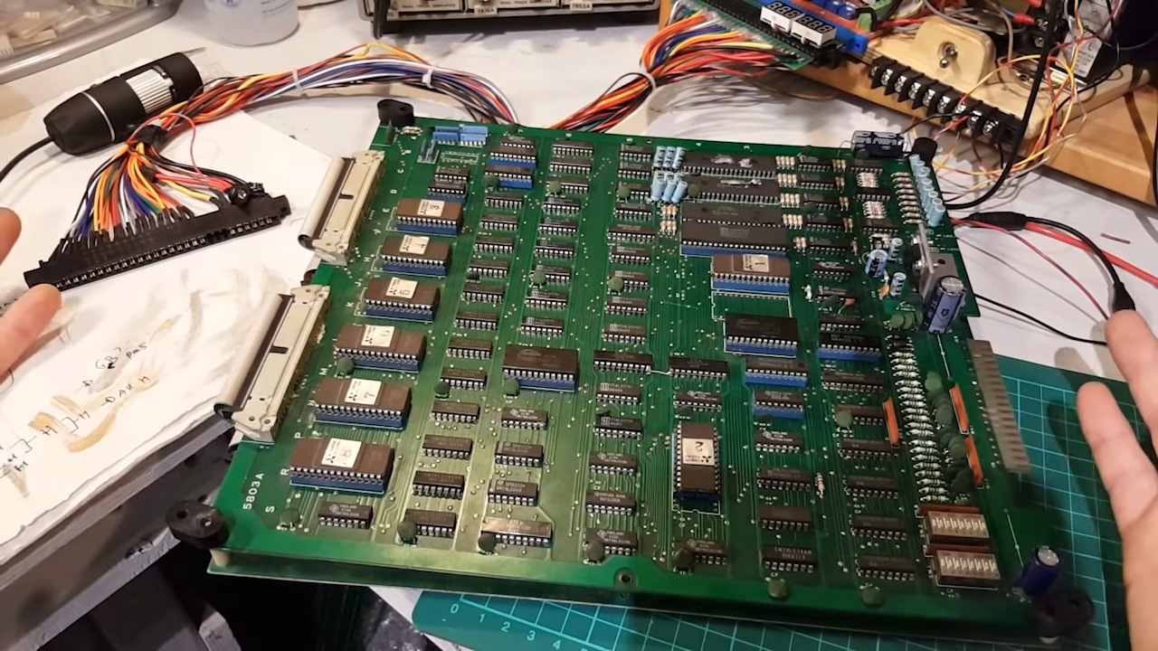
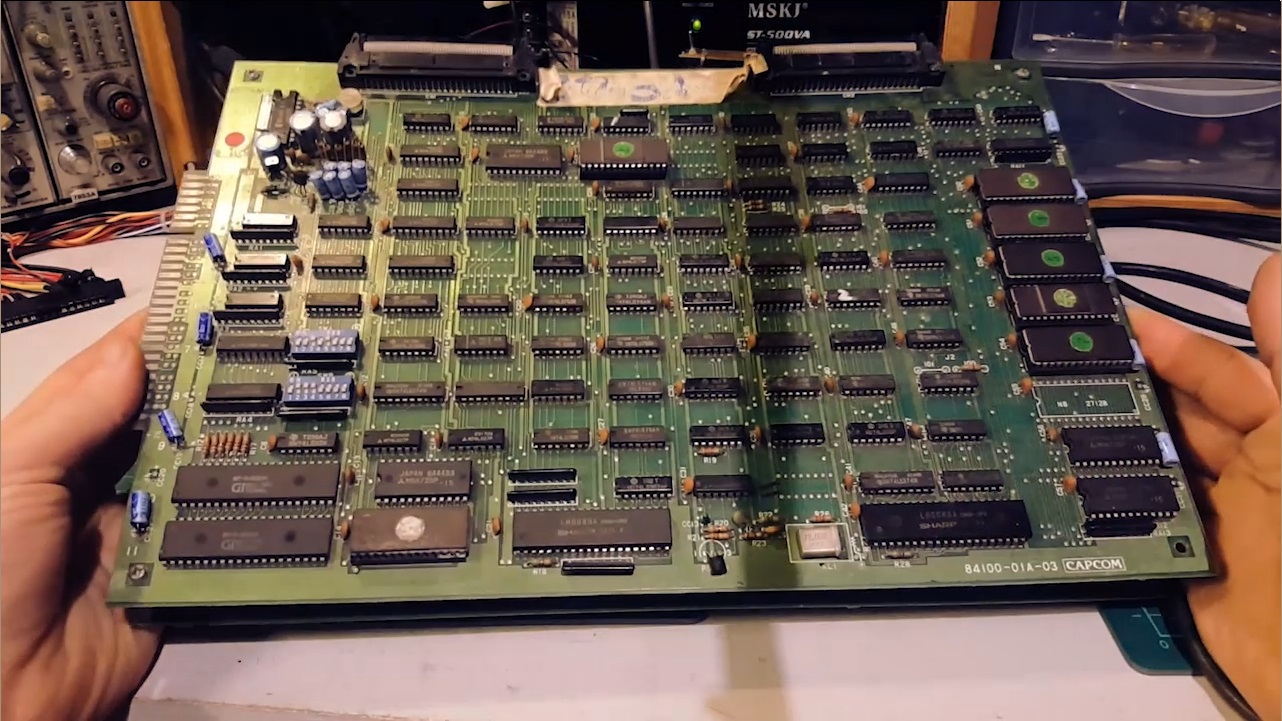
I recently got a few boxes non working pcbs from a friend of mine and decided to start looking at them.
This is the first one, an original Capcom 1942 pcb.
It came with a jamma adapter so I was happy I didn’t have to spend time making one.
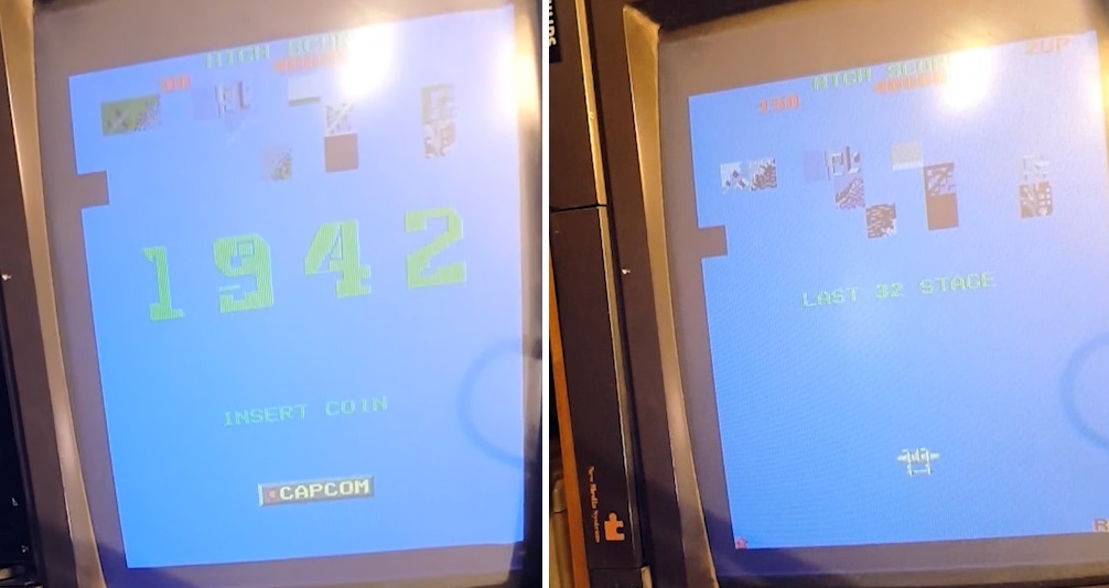
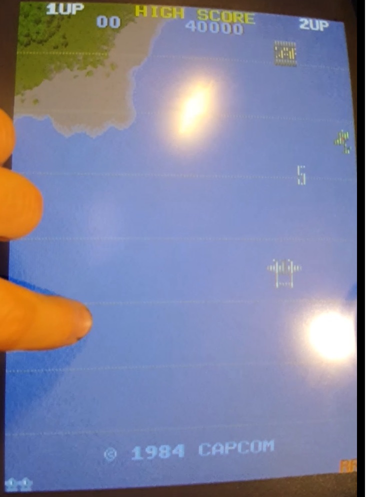
Upon starting the board, it came up as evident why it had been marked as non working
No Background layer instead showing some corrupted background
Some sprites were showing up incorrectly and only half the sprites was visible on screen
Luckily the sound was all working… for now.
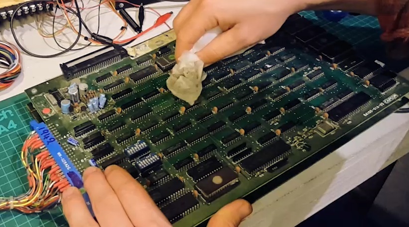
Since the board was very dusty, I went ahead and cleaned it and checked all the eproms in mame.
When putting the boards back together I quickly discovered the board ribbon connectors were corroded.
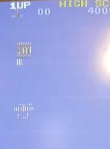
I changed those and gave the sockets and clean and now the board was booting to a much more acceptable state
The background layer was restored but the sprites were still “halved” and showing halved white lines across the screen.
I first thought I’d address the halved sprite data.
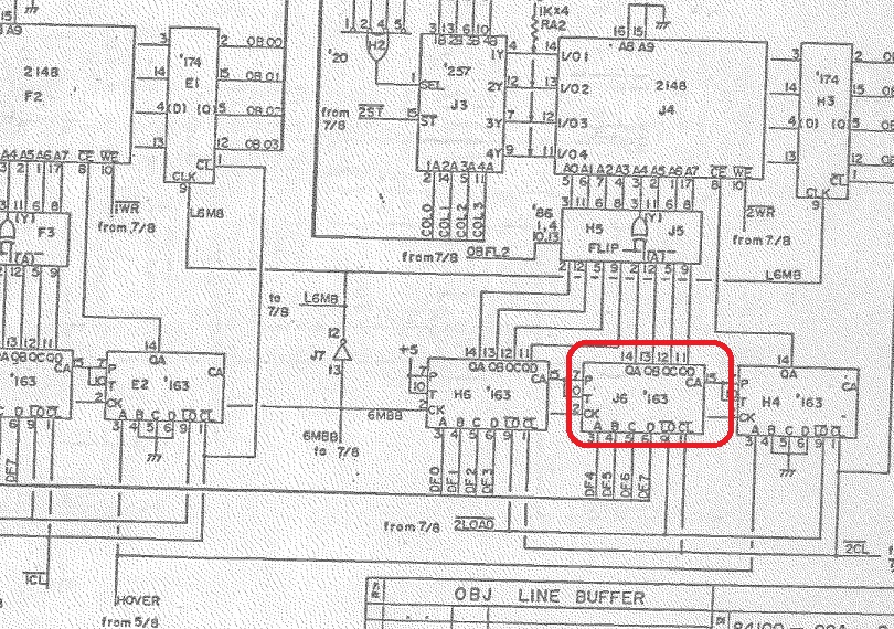
The schematics show that they are processed by two parallel identical circuits (page 16 / OBJ LINE BUFFER)
I started probing around the RAM at J4 and found Pin 15 and 14 of J6 (74ls163) were set high.
Comparing the readings from the other half of the sprite processing at F4 gave a different reading.
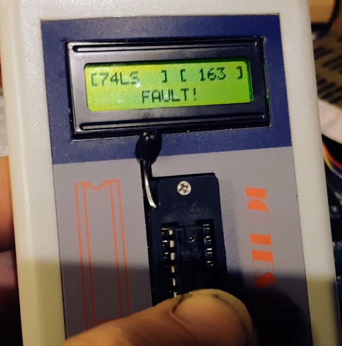
I tried to piggy back a known working ls163 and it completely restored the sprites and removed the vertical lines .
Time to remove it and socket a nice new IC. ( btw, this was a Fujitsu IC, what a surprise)
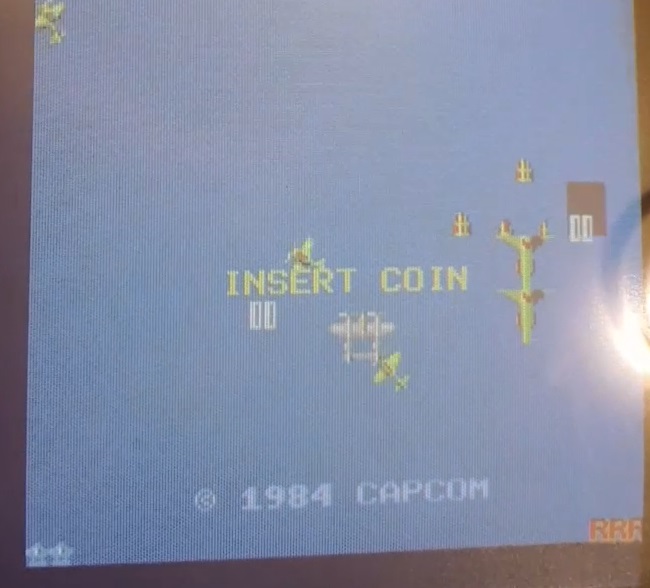
Nice ! Now to address the other sprite issue with incorrect sprites being displayed in specific segment.
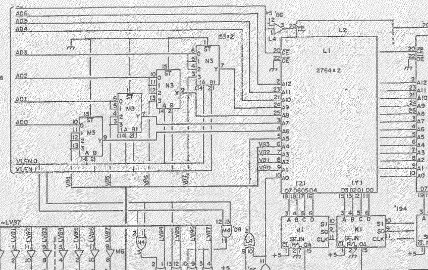
The eproms had checked fine so I reasoned this was an issue at the addressing level.I assumed that a problem on the data bus would give us random or consistently corrupted data, but here we have very valid data being used in the wrong spot.
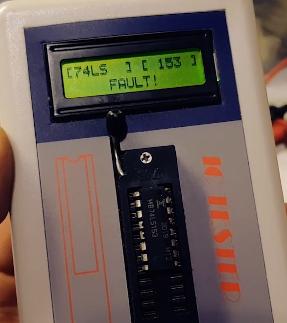
So I thought I’d start looking at the LS153 at M3 and N3. Indeed pins 7 and 9 of N3 were floating.
Replacing it completely restored all our sprites… BUT
I’ve just lost all sounds!! The entire board when silent.
While I’m full aware this can happen with boards it doesn’t mean it’s not 100% heartbreaking, especially when you thought you’d completely fixed the board.
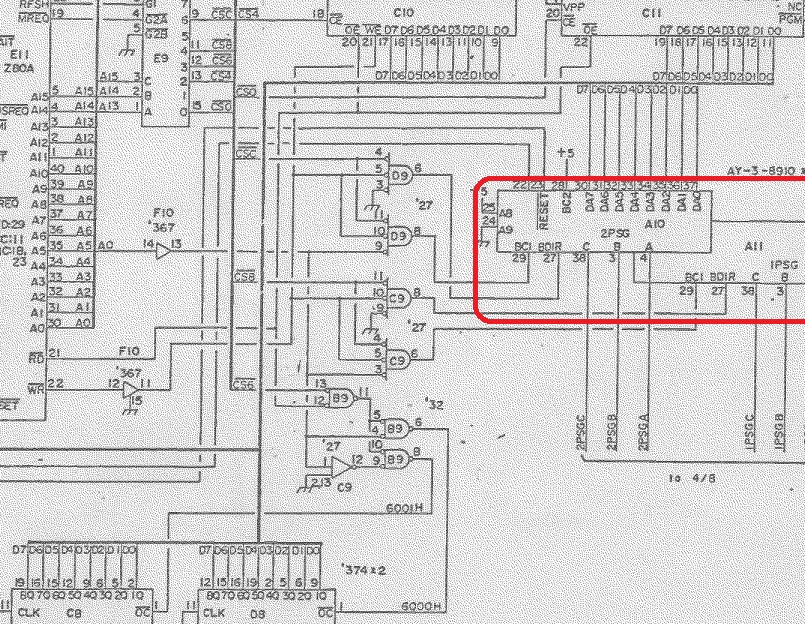
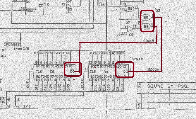
sooo looking at the schematics for the sound system at page 3 I can see this is generated by two AY-3-8910 square wave generators.
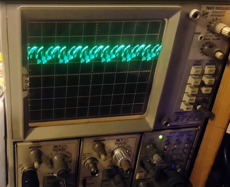
The output of both chips on pins 3,4 and 38 were completely silent. So I went ahead and re-checked the eprom first and it check fine. Looking at the data lines I could see a sort of “compressed signal” so I was wondering if sth on the data bus was causing the data levels to be that way and was preventing the sound chips from toggling high and low and thus generating the signal … maybe ?
I went ahead and removed the z80 and ram at E11 and C10 respectively but nope, they checked fine. I did the same thing with the ls374 flip-flops at C8 and D8 since these drive the sound generating events. No luck. I went on many wild goose chases with this issue and still couldn’t find anything wrong. A quick chat with Porchy and his advice was to get some sleep and leave it alone for a few days…
So I did that.
…
Picking this back after a week or so, I used a wire connected to ground, and driving the OE line on the ram with it, I was able to hear some sounds and music at random intervals, this meant the data lines were ok and could trigger the sound ICs. So I moved away from the Z80 section of the circuit and that the issue was most likely with the chip enabling section of the circuit so I started looking at the ICs driving the enable lines.
I checked D9, C9 and B9 but all the signals seemed healthy on the scope. Comparing this with a known working board I couldn’t seen anything jumping out at me. This is where I wish I had a proper logic analyser but at least I felt I was on the right path. But still I had a feeling I was looking at the right area, I started removing and testing D9, C9 (mental note: invest in a logic comparator) and then finally B9 which tested faulty
The last IC on that entire sound circuit !!
Looking back at the circuit it makes sense, this IC enables the output control of the LS374 driving the event data into the sound circuit. Without this, the sound circuit doesn’t “know” it’s supposed to generate a sound.
Replacing it restored all the sound circuit .
Board all fixed, and lessons learned:
Sometimes getting some sleep and leaving a board alone for a while is best
Always check the enable lines first
… and start looking into getting a logic analyser.

 So I fired up the board and it booted up just fine. However there was absolutely no sound coming out.