Another PCB which has been collecting dust on a pile. I got myself motivated to repair it.
Symptoms
The PCB will not boot, all you see is a white screen.
Decided to check the clock circuit first to ensure the CPU was running, it was, so clock circuit is fine. Next I checked the CPU ROMs, and found a bad ROM at location 8N. Burned a new ROM and inserted it, now game is booting but with issues.
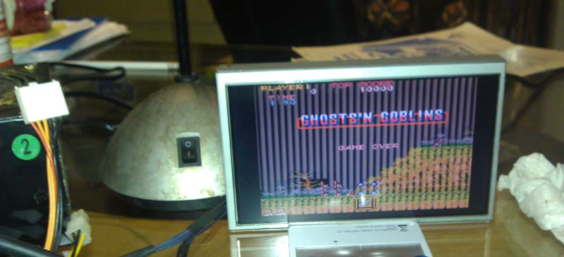
There were absolutely no sprites, and I could not coin the PCB up to start either. The background was full of jail bars.
I first checked the sprite PROM on the A board at 2E, if this goes bad the sprites will dissapear. Both the PROM and socket checked out good. So, my attention turned to the lower B board as this handles all the sprite processing.
It is interesting to note that GnG PCB will boot without the B board but without sprites of course. Handy for troubleshooting.
These Capcom PCBs have all the copper path traces masked, obviously an attempt to stop the bootleggers. Luckily, schemes are available, and they are sectioned off into relevant areas of the PCB which is nice.
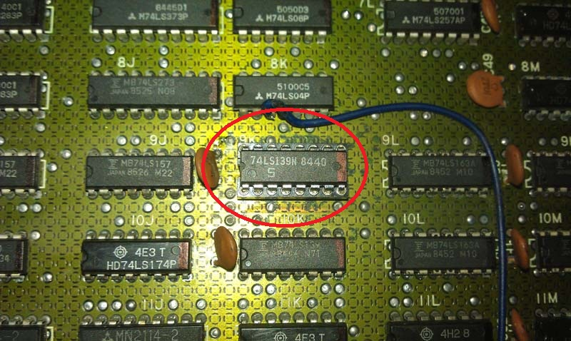
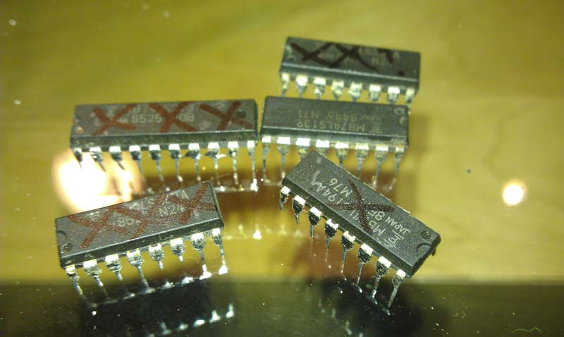
My attention turned to the B board to get the sprites back up. Found a LS139 Decoder IC on the B board at 9K which for some reason was plagued with rust, I checked it and found that it was completely dead, the rust must have worked its way up.
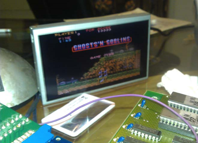
Socketed and replaced it and now we have some sprites which are all wrong, but at least we have sprites.
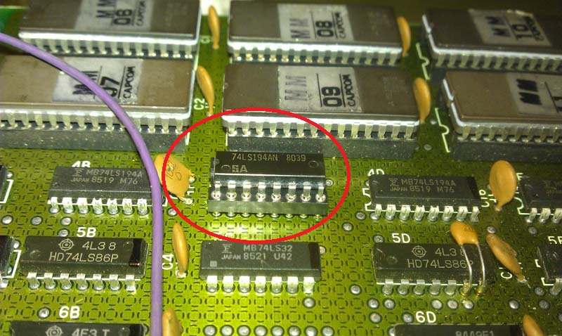
Looked around the graphics ROM addressing circuit and eventually found a LS194 Decoder on board B at location 4C with pins 13 and 14 stuck high.
Socketed and replaced and now the jailbars have gone.
Whilst I was troubleshooting, I noticed that the RED had completely failed and I was left with just BLUE and GREEN, nice! I checked the supergun setup, but no it was the PCB which had failed.
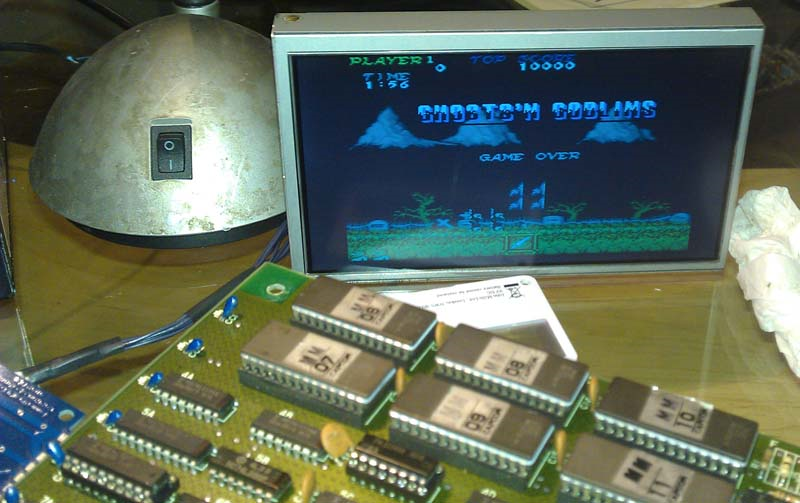
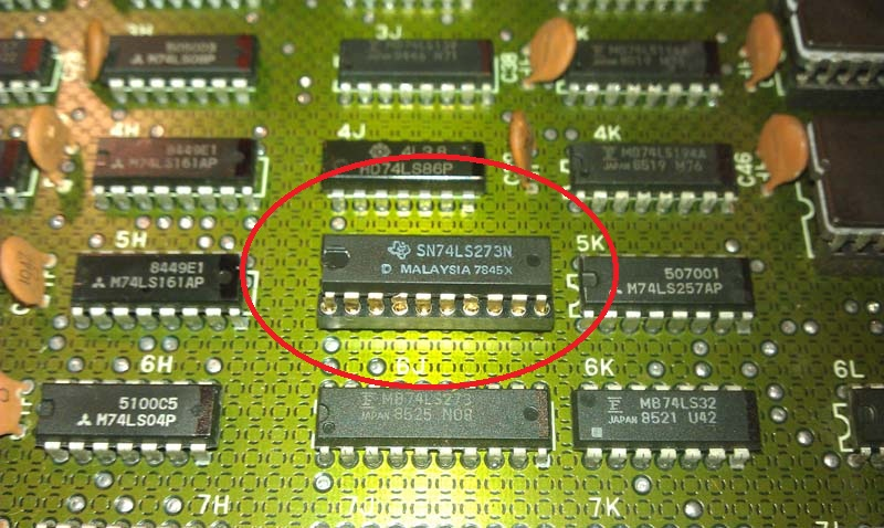
I carried on looking at the sprite circuits and found a LS273 Octal Flip-Flop which had completely failed.
Socketed and replaced it, we now have all the sprites back!
I flipped the PCB over to look at the A board, and using the schemes I could see that a LS367 Hex Bus at location 6C was the final stage for the RED output. I checked it and found that pin 11 was stuck High.
Socketed and replaced it and the RED came back!
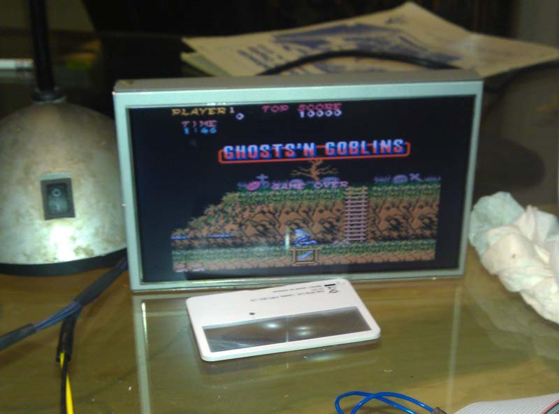
Finally, had to resolve the issue of the PCB not coining up. The coin up function works in the same was as the game inputs, so I knew I was looking for another LS367 Hex Bus on the A board. I checked the schemes again and it told me the LS367 Hex Bus at location 8A controlled the coin up input. I checked the LS367 and found pin 4 was stuck Low.
Socketed and replaced it, now coining up.
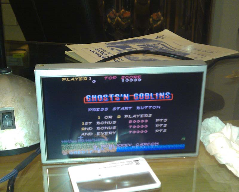
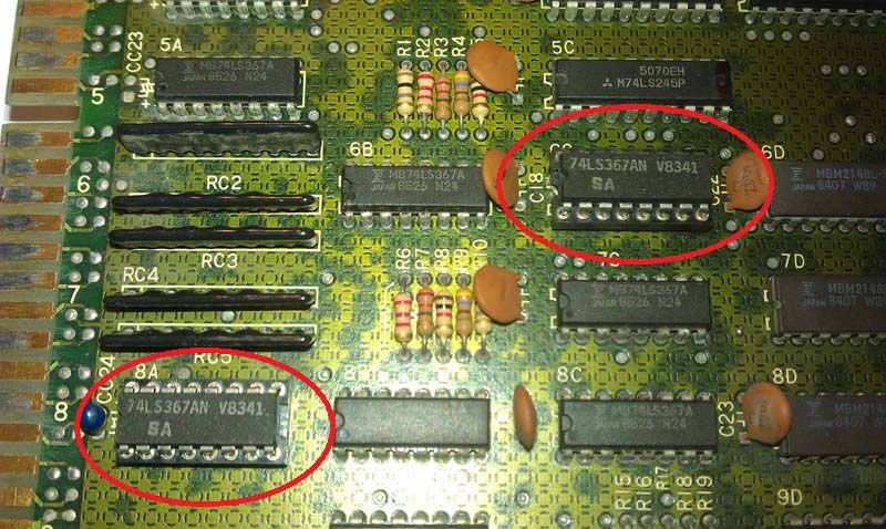
PCB finally repaired.
One Response to “Ghosts’n Goblins repair log #1”
Sorry, the comment form is closed at this time.

Great work. I have a ghosts n goblins that has been aching for repair for a while. When I got it someone (definitely not me. probably) had ran 12v down the wrong circuit and smoked an audio IC and after I fixed that it works and boots but there are some graphical issues. Your analysis is a great help for figuring out the right area to play around with.