Tutorial: CRT Color Calibration for Video Games

 General, Guides, Technical Info  Comments Off on Tutorial: CRT Color Calibration for Video Games
Apr 242024
 

Last Updated: 4/24/2024

This tutorial is a straightforward procedure for using a colorimeter to calibrate an arcade cab or consumer CRT. Using a colorimeter is perfect for people that want their displays calibrated to a high standard with no “eyeballing it” or guesswork involved.

Display color calibration in a nutshell is precisely matching the contrast, brightness and colors of a video display against a reference standard such that (A) the calibrated display looks the same as other calibrated displays and (B) subtle details in video games aren’t missed due to either color washout (white point too high) or black crush (black point too low).

Up front, here’s some vocabulary words that this tutorial uses:

  • White Point: The measurement of the brightest white your monitor can display.
  • Black Point: The measurement of the darkest shadow your monitor can display.
  • Contrast: Adjusts the White Point of the RGB color guns equally.
  • Brightness: Adjusts the Black Point of the RGB color guns equally.
  • Gain or Drive: Individually adjusts the White Point of each Red, Blue and Green color gun.
  • Cutoff or Bias: Individually adjusts the Black Point of each Red, Blue and Green color gun.
  • Color Temperature: Expressed in kelvins, color temperature is a parameter comparing the color of a light source (ie your display or a light bulb) against an real-world reference light source (ie the sun). Lower color temperatures (< 3000 K) are considered “warm” (red or yellowish) while higher color temperatures (> 5000 K) are considered “cold” (blueish).
    • The abbreviation for 6500 kelvin color temperature is D65 while the abbreviation for 9300 kelvin is D93.

Note that display color calibration is a VERY deep rabbit hole with a lot of information, detail and nuance. This guide is intended for enthusiasts that just want a procedure they can quickly step through to make their displays look nice. There’s much more you can do in addition to what I’ve written up here if you want to be very precise with your display’s calibration.

If you want to delve deeper into the world of color calibration, consider these resources and articles:

This tutorial steps you through a white point balance procedure for your display, but does not cover adjustment of the RGB primary and secondaries since adjustments to those are very specific to each CRT model. Geometry adjustment is also not covered here.

Necessary Calibration Components
  • Laptop or desktop Windows computer to run the Colorimeter
  • Colorimeter to accurately read color measurements off the display
  • Pattern Generator to push accurate calibration images to the display
  • Calibration Software that reads the values from the Colorimeter and displays them to you in a readable format
What I Use
  • X-Rite I1 Display Pro colorimeter – it’s around $30 – $100 used from Ebay.
  • MiSTer FPGA with MiSTercade add-on running HCFR core Pattern Generator and SNES 240P Test Suite – Download Link
    • Other good choices for a Pattern Generator are:
    • 240P Test Suite running on a game console
    • PGenerator running on a Raspberry Pi
      • PGenerator is a great pattern generation option since it supports 15 khz output for CRTs and the laptop you’re using to read measurements can control it automatically, but it is tricky to setup for the first time. There is an excellent YouTube tutorial by StickFreaks available here: https://youtu.be/D6z0wS5oRoE
    • DVD player running the FreeCalRec601 disc
    • HCFR – the same program that interfaces with the colorimeter – if the display you’re calibrating supports an output resolution that your HCFR PC supports.
  • HCFR calibration software

If applicable, use a color generator that matches what will be connected to your display the most often – ie, if you’ll be running a MISTer FPGA in an arcade cab, use a MiSTer as your color generator.

White Point Reference Selection

One decision you should make before you start is the white point standard you want your display calibrated against.

For retro video games, there are two target white point standards to consider:

  • D65 is considered the standard that US CRTs were calibrated for in the 80s-90s. It is a “warmer” white point and thus the display will have stronger red output.
  • D93 is considered the standard that Japanese televisions were calibrated for in the 80s-90s. Is is a “cooler” white point and thus the display will have a stronger blue output.
  • Choosing one or the other is a personal preference.
    Personally, I go with D65 for displays with US tubes (ie Zenith, RCA, Magnavox) and D93 for Japanese tubes (Sony, Toshiba, Panasonic, JVC, Hitachi)
  • There’s a thorough writeup on D65 vs D93 here: https://www.retrorgb.com/colour-malarkey.html

Procedure

These instructions assume you’re using HCFR as your colorimeter interface software on your Windows laptop.

One-time only software setup

1) Download and install the free HCFR software from here:
https://sourceforge.net/projects/hcfr/files/

2) Launch HCFR.

3) Click on the Advanced menu and choose Preferences.

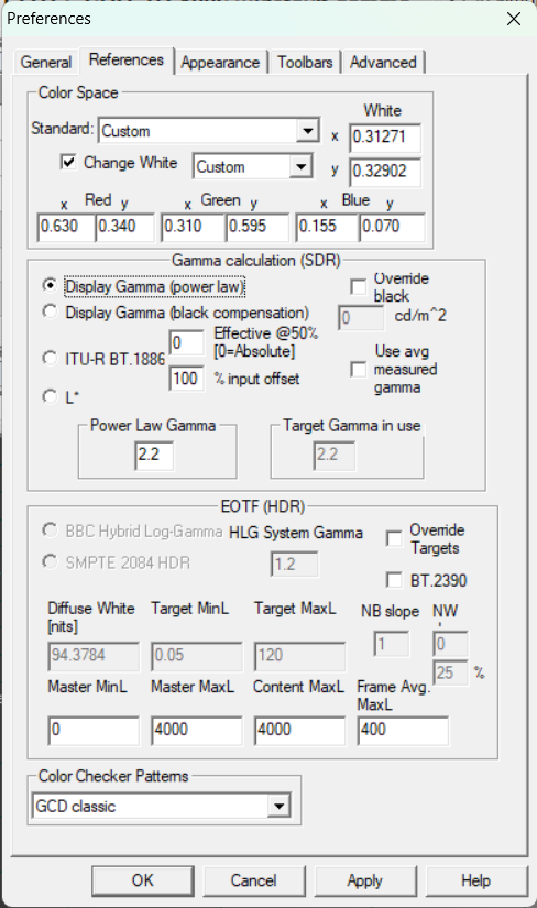
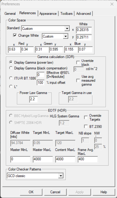
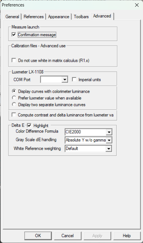
4) Click on the References tab. Set the settings as follows:

D65 White PointD93 White PointAdvanced Tab

6) Click OK to close the Preferences window.

Technical Note: the values entered for the Red, Green and Blue references in HCFR correspond to the SMPTE-C phospher specification. https://en.wikipedia.org/wiki/NTSC#Colorimetry and HCFR Calibration – Custom Coordinates

Calibrating a display

IMPORTANT NOTE ABOUT TERMINOLOGY
CRT manufacturers often confuse the labeling for Contrast, Brightness, Drive and Cutoff.

“Contrast” is the term for adjusting the White Point level.

“Brightness” and “Black Level” are two interchangeable terms for the Black Point adjustment. I use “Brightness” in this guide, but yours may be labeled “Black Level”.

“Drive” and “Gain” are two interchangeable names for the upper-end Red, Green and Blue color gun adjustments. I use “Drive” in this guide, but yours might be labeled Gain.

“Cutoff” and “Bias” are two interchangeable names for the low-end Red, Green and Blue color gun adjustments. I use “Cutoff” in this guide, but yours may be labeled Bias.

CRT and colorimeter setup
1) Connect your test pattern generator to the display.

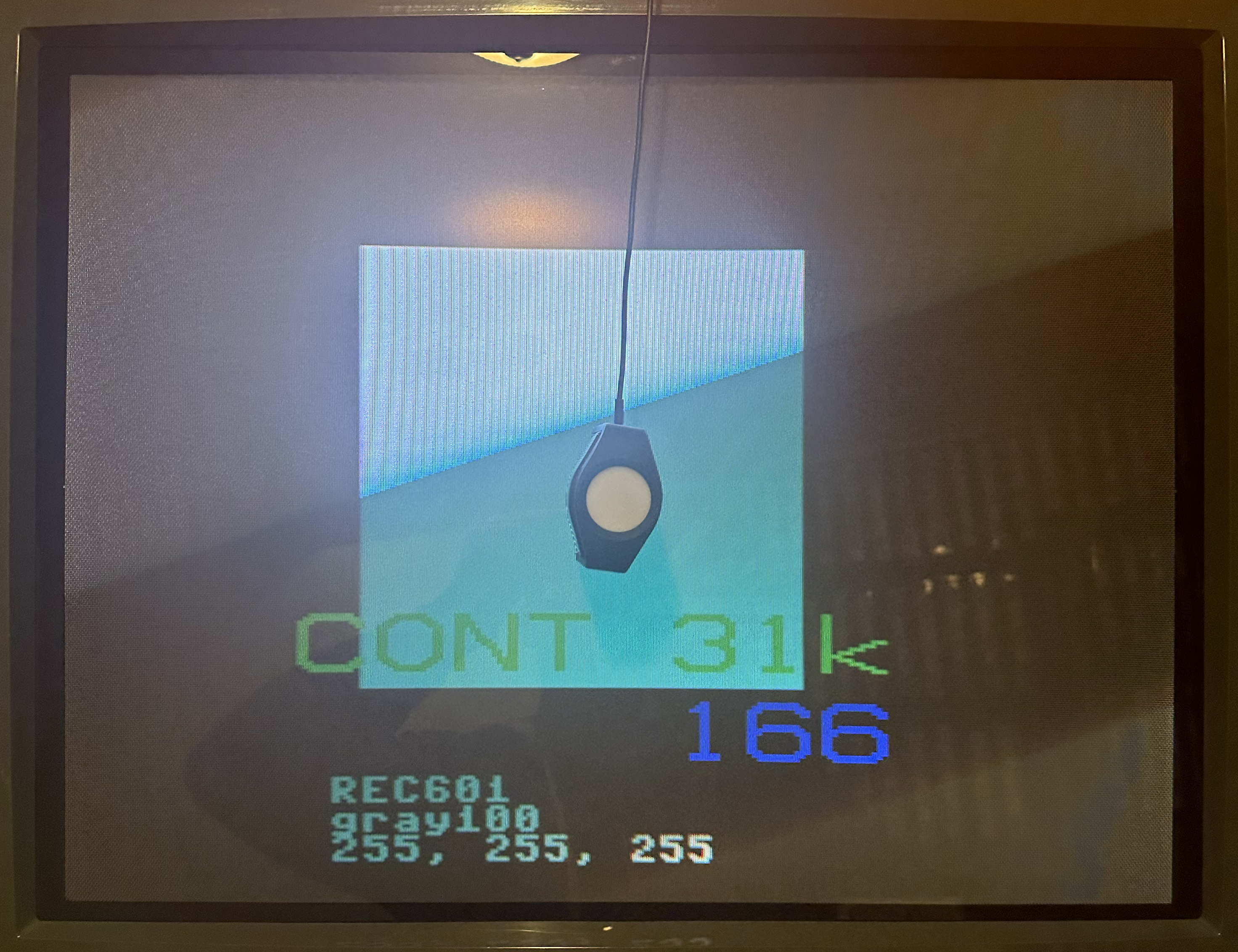
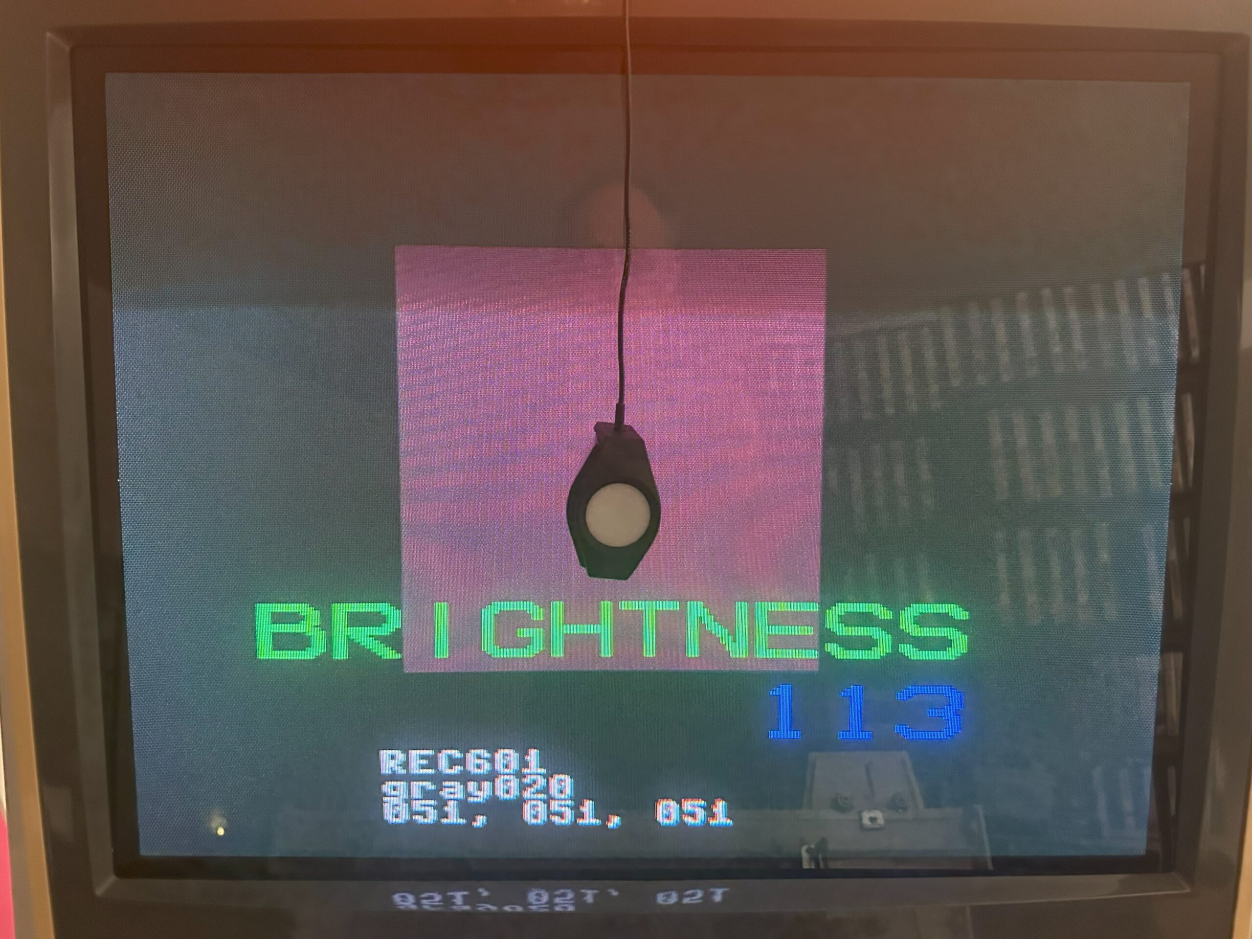
2) Power on the display. Display a 100% solid white test pattern.
In the 240P Test Suite, go to “Test Patterns” -> “White Screen”.

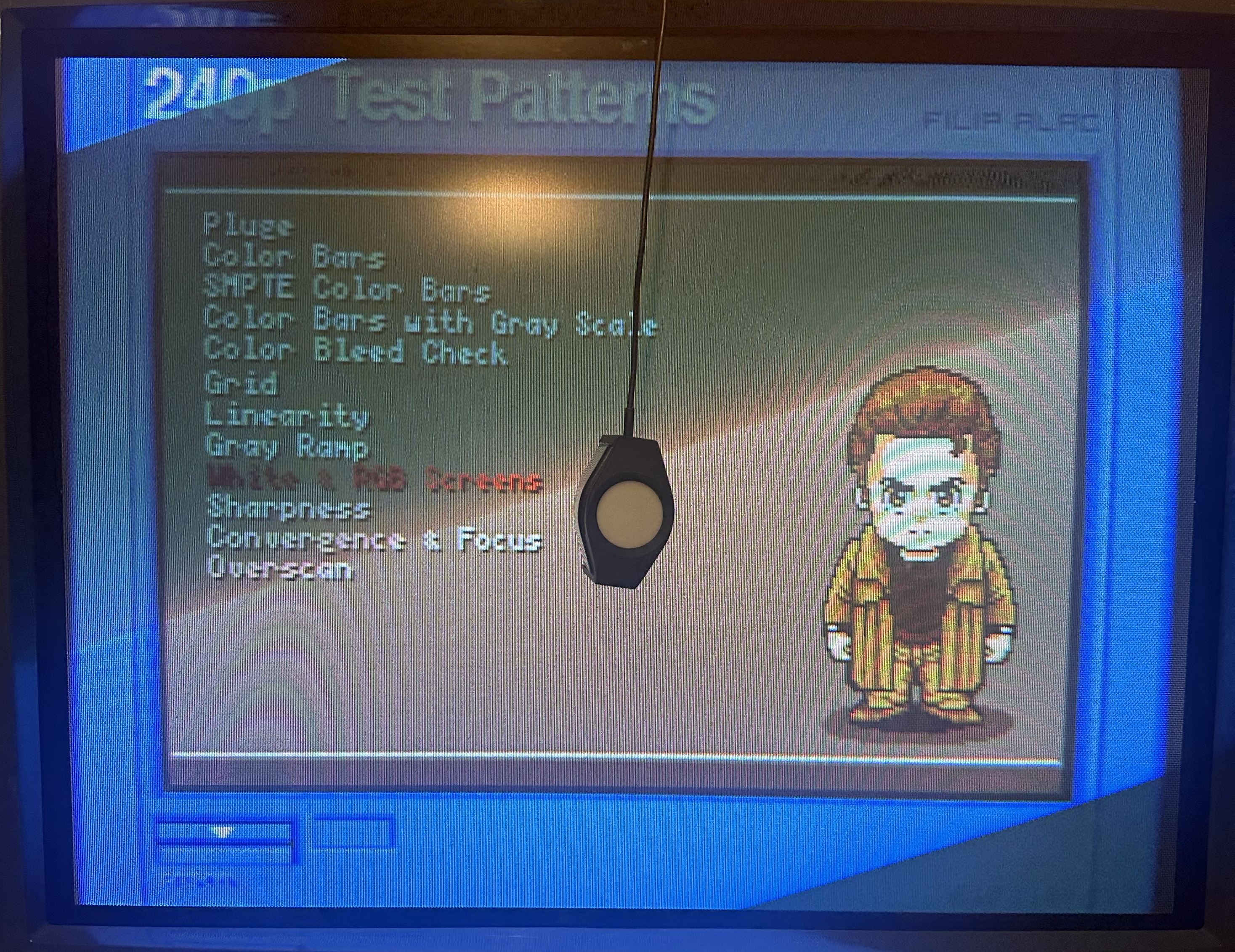
3) Wipe down the monitor glass with glass cleaner. Place the colorimeter directly on the glass in the center of the screen. Place a book or something heavy on top of the cable to stop it from sliding or falling off the screen.

4) Wait one hour with the screen on all-white to let the CRT and chassis warm up.

5) Connect the colorimeter to your laptop running HCRF with the USB cable. Launch HCRF.

6) Click on the “File” menu and choose “New”.

7) On the Generator Selection screen, choose:

  • DVD manual: if you’re using a pattern generator that can’t be controlled from the laptop, such as MiSTer HCRF core, 240P Test Suite or a DVD Player.
  • Automatic: if the laptop is the pattern generator and thus connected to the cab display as a secondary monitor.
    • PGenerator will also be detected and used by HCFR when Automatic is selected.

8) Select your model of Colorimeter from the sensor list, select “Do not use a meter correction file” and click Finish.

9) Your meter might now ask what kind of display you’re calibrating – choose “CRT” or “Refresh Display”. Also, Reading Type should be set to “Display”. Click the Calibrate Meter button. Some meters will then ask you to display a white image of 80% IRE or higher. You’re already displaying a 100% IRE all-white screen, so just click OK to finish the calibration.

10) In the main HCFR window that appears, click on the Green Triangle button in the menu bar to start taking readings.

Adjustments – Ideally, you’ll want to do this with the room as dark as possible.

Flyback Screen Dial – Initial Approximate Calibration
Source: https://emphatic.se/?p=710
Archived Copy: PDF

NOTE: If you don’t have straight-forward access to your CRT’s flyback, set each Drive, Cutoff, Contrast, and Brightness setting to the center position and move on to the next section.

1) Set the CRT controls as follows:

  • Each RGB Drive: All the way down.
  • Each RGB Cutoff: Center position.
  • Contrast: Center position.
  • Brightness: Center position.

2) Display a white grid pattern.

In the 240P Test Suite, go to “Test Patterns” -> “Grid”.

3) Turn the Screen dial on the flyback down (counter-clockwise) until the display is completely dark and pitch black. You want to go just past the last trace of the grid.

4) Turn each RGB Cutoff up until you see the black space around the white grid turn into the color you’re adjusting. Then turn it down until the black is perfectly black again.

5) Turn each RGB Drive up until the grid is really white without bleeding out / turning blurry.

Now the CRT is broadly dialed in, we can fine tune the adjustment using the colorimeter.

Contrast and Brightness – Precise Calibration Part 1
Source 1: https://consolemods.org/wiki/CRT:CRT_Color_Calibration_Guide
Source 2: http://www.curtpalme.com/forum/viewtopic.php?t=10457
Archive: PDF

1) Display a 100% IRE test pattern.
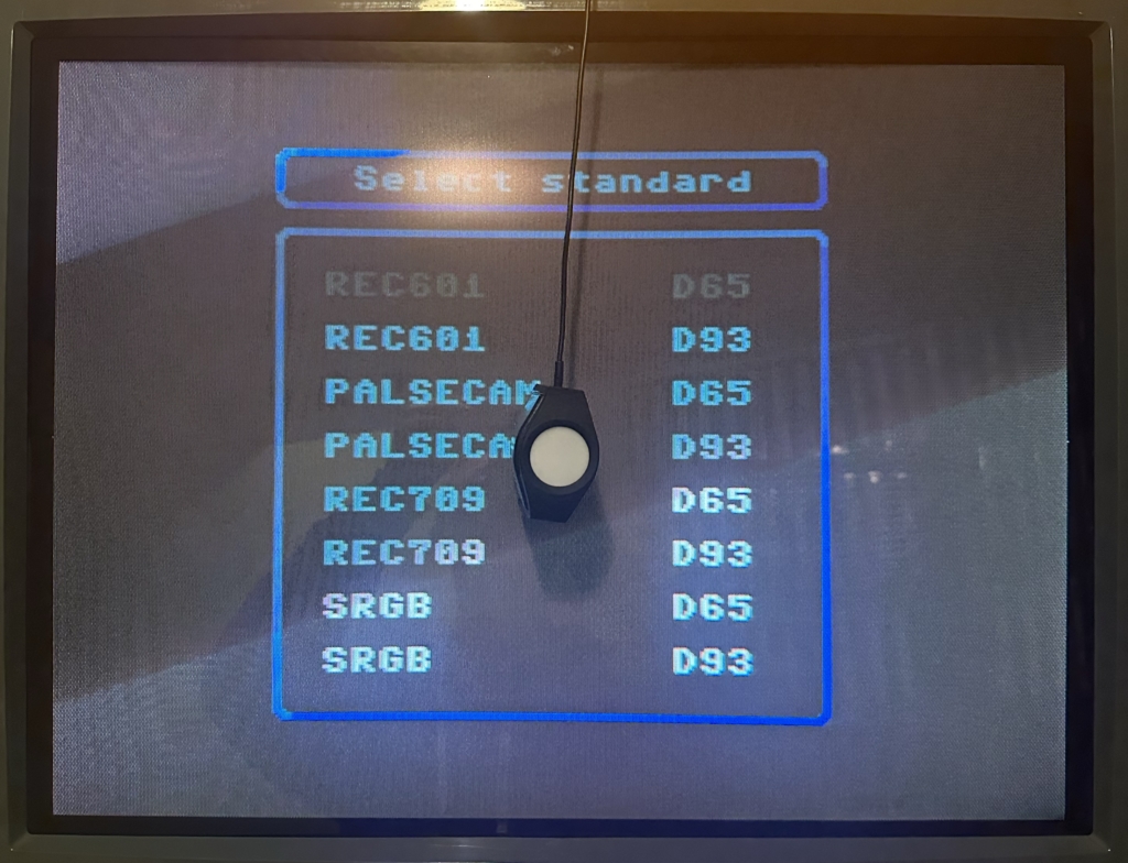
In the MiSTer HCFR core, choose “REC601 D65” or “REC601 D93” from the menu depending on which white point standard you’re using. Up and Down on the controller will cycle the IRE level up or down in 10% increments.
In the 240P Test Suite, back out and go to “Test Patterns” -> “100 IRE”. Depending on the console, some control buttons will adjust the IRE level up or down in 10% increments.

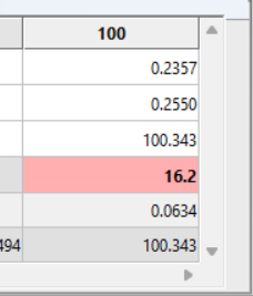
2) Click on the 100 Column in HCRF. If the colorimeter isn’t currently taking readings, click on the green Triangle button in the upper-middle of the toolbar.

The “Y” measurement tells you how bright your screen is. Typically, you want it at 100 nits. If you plan to always run your display in a dark setting, you may want to go down to either 95 or 90.

Adjust the SubContrast dial (if you have one; Contrast otherwise) until the Y readout hits your target.

  • If your chassis doesn’t have any Contrast adjustment dials or if you can’t get the Contrast to go high enough to hit your target, try adjusting the Red, Green and Blue Drive/Gain pots evenly upward.

3) Click on the 20 Column in HCRF. Change your pattern generator to display a 20% IRE test pattern.

4) Your target now for the Y value is 0.3% of the reading at IRE 100.
So if 100 nits is your IRE 100 target, 3.0 is what you want Y to read at IRE 20.
HCRF also calculates the target value for you – look at “Y Target”.

Adjust the SubBrightness dial (if you have one; Brightness otherwise) until the Y readout hits your target.
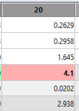
If you can’t go low or high enough try adjusting the Red, Green and Blue Cutoff pots evenly.

  • Note that aged chassis components and tubes may have trouble hitting these high and/or low targets. In that case, just get as close as you can.

5) When you change Brightness, it affects Contrast and vice-versa, so repeat Steps 2-4 until the Brightness and Contrast are balanced against each other with the appropriate Y target for each.

Drive and Cutoffs – Precise Calibration Part 2
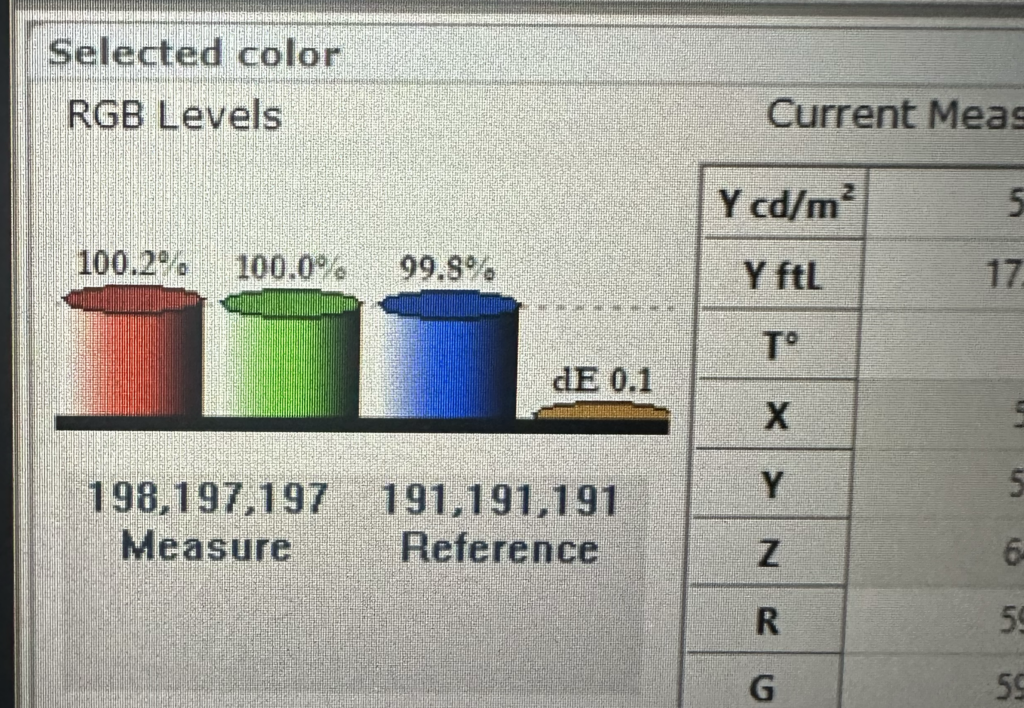
1) Click on the 80 Column in HCRF. Change your pattern generator to display a 80% IRE test pattern.

2) Look at the gauges in the lower-left corner of HCFR. The Red, Green and Blue gauges show your levels relative to the target, while the yellow gauge shows your Delta E (deviation) away from the target. As the RGB gauges get close to 100%, the Delta E gauge will drop. Your goal is to get Delta E as close to zero as possible.

Adjust the Blue and Red Drive pots until the gauges are as close to 100% as possible and Delta E is as close to 0 as possible. Adjust Blue first before Red.

Adjusting Green will scew both the Red and Blue levels, so you shouldn’t touch the Green pot unless you can’t get Red or Blue to adjust far enough to reach your targets. You’ll notice as you adjust the Red and Blue levels closer to 100%, the Green will be pulled there as well.

3) Click on the 20 Column in HCRF. Change your pattern generator to display a 20% IRE test pattern.

4) Adjust the Blue and Red Cutoff pots until the gauges are as close to 100% as possible. Adjust the Blue first before Red.

Adjusting Green will scew the Red and Blue levels, so you shouldn’t touch the Green pot unless you can’t get Red or Blue to adjust far enough to reach your targets. You’ll notice as you adjust the Red and Blue levels closer to 100%, the Green will be pulled there as well.

5) When you change the Drive pots, the Cutoff target shifts and vice-versa, so repeat Steps 1 – 4, going back and forth between 20 and 80 IRE and adjusting Cutoff and Drive respectively until both of them are as close to 100.0% RGB and 0.0 Delta E readings as possible on the gauges.

Now, the display is pretty well dialed in at this point, but if you’re extra picky, repeat the Part 1 – Contrast and Brightness steps one more time, because adjusting the Drive and Cutoffs will have shifted those values a little bit. If you do end up readjusting Contrast and Brightness, you’ll also have to readjust the Drive and Cutoffs again afterward as well, but none of them will need very much readjustment.

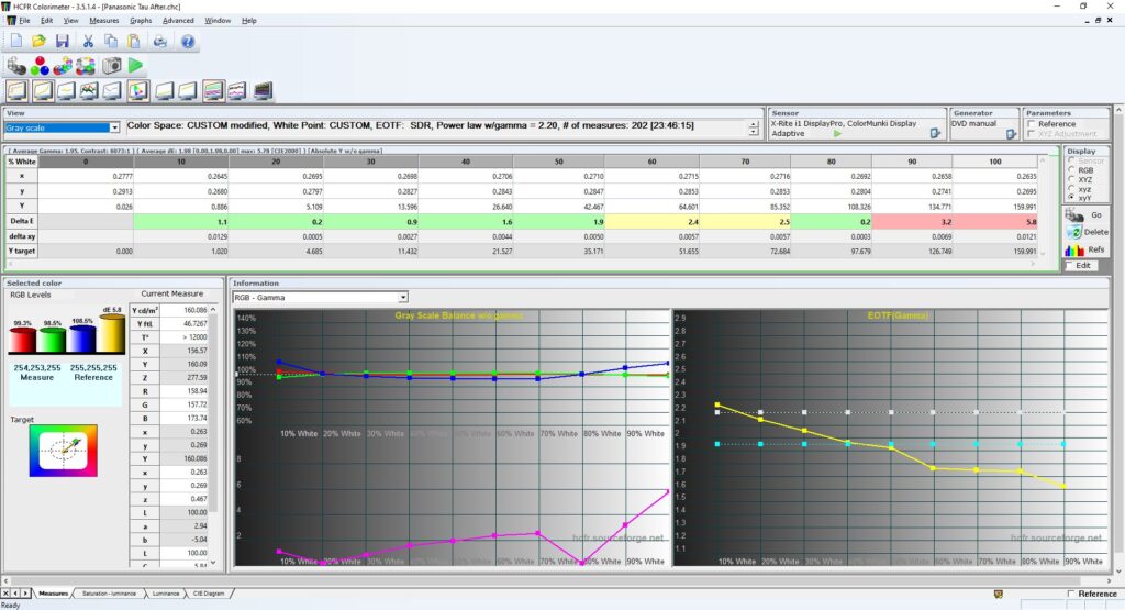
Verifying the White Balance Calibration
If you’d like to check your cab CRT now and see how the White Balance calibration holds up across the gamma range, do the following:

1) In HCFR, click the Green Triangle to stop taking constant readings.

2) Click the Measures menu and choose “Gray scale”, and click Yes at the prompt.

3) The software will prompt you to “set 0% grey level”. Set an IRE 0% test pattern on your generator.
In 240P Test Suite, use the L and R buttons on the controller to set IRE to 0, and click OK.

4) After a moment, the software will now prompt to “set 10% grey level”. Set an IRE 10% test pattern on your generator.
In 240P Test Suite, use the L and R buttons to set IRE to 10, and click OK. Repeat all the way up through the 10 incrementing IRE levels.

5) When the measurement is complete, look at the DeltaE row. Recall that DeltaE measures your variance from the perfect white balance target. If all ten cells are green (Delta E < 2.0) then you’re in good shape – your white balance is approximately on-par with a professional CRT. If some or all of the cells are yellow (Delta E between 2.0 and 3.0) then you’re approximately on par with a consumer CRT. If some or all of the cells are red (Delta E > 3.0) then you’re off target – either the calibration is wrong, your chassis PCB needs servicing, or the color guns in your tube are worn out.

Also, with Gray Scale selected from the drop-down in the upper-left corner, make a note of your Average Gamma and your Contrast Ratio. Ideally, you want an Average Gamma of 2.2 and an Average Contrast Ratio of at least 1000 : 1, but your results will vary based on tube and chassis age, specs, etc.

This post-calibration result of a Panasonic Tau consumer CRT shows some drift at the 90 and 100 IRE levels.

Note that calibration drifts as the tube and caps age – you may want to “tune up” your calibration every couple of years.

Post-Calibration Examples
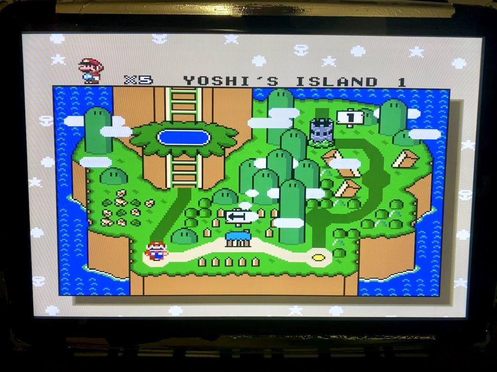
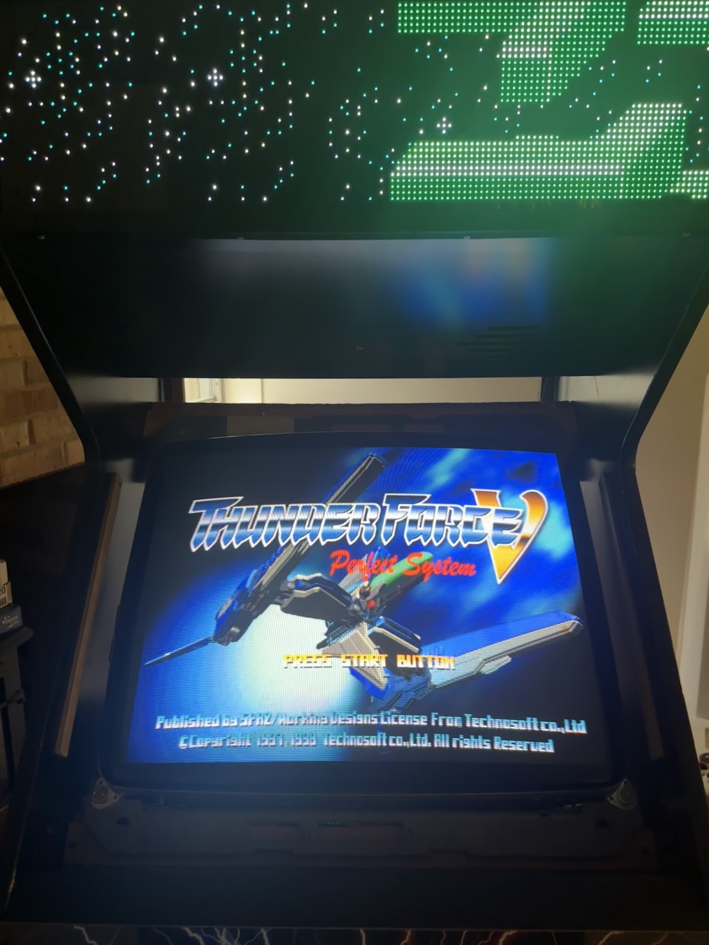
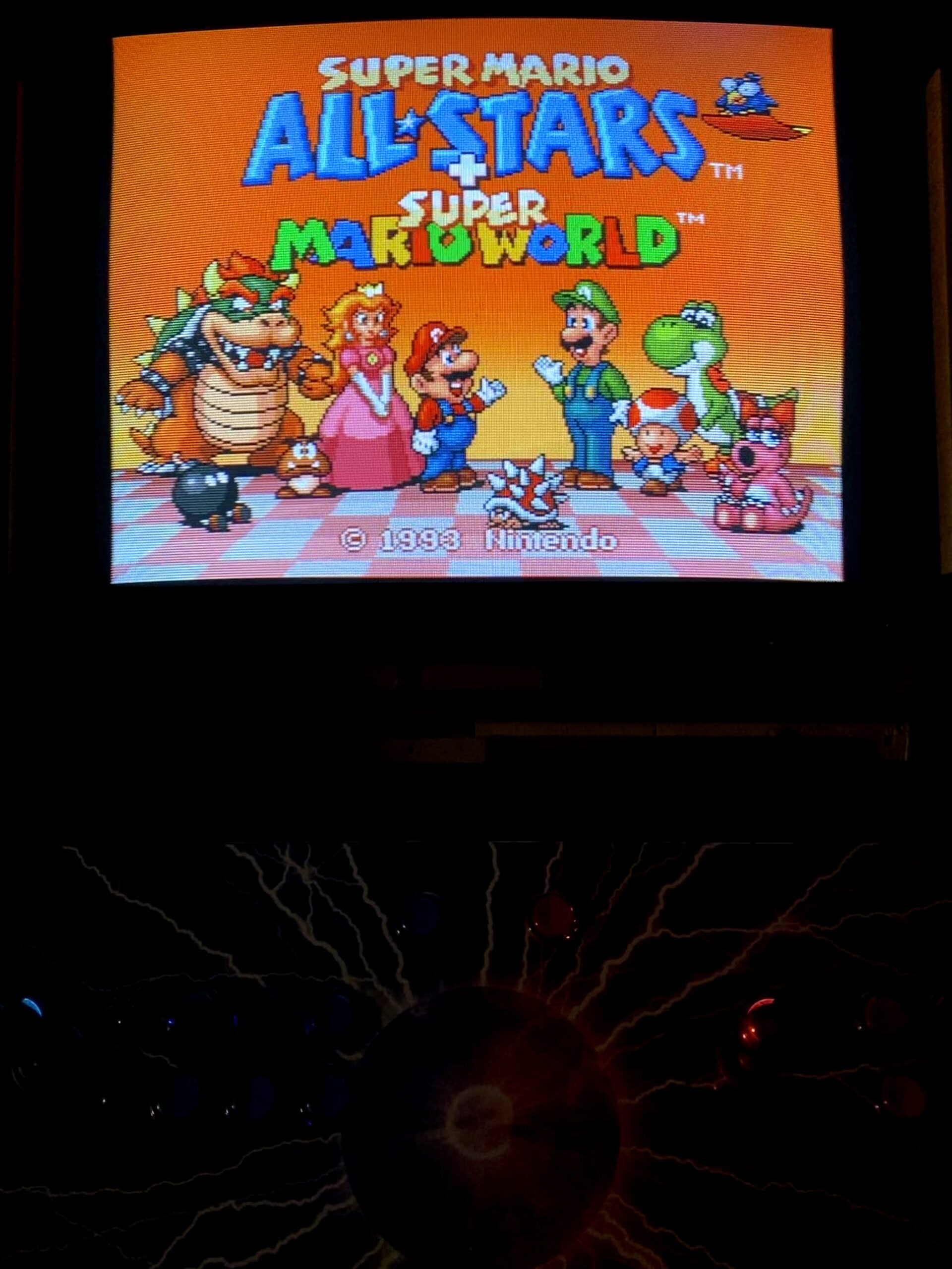
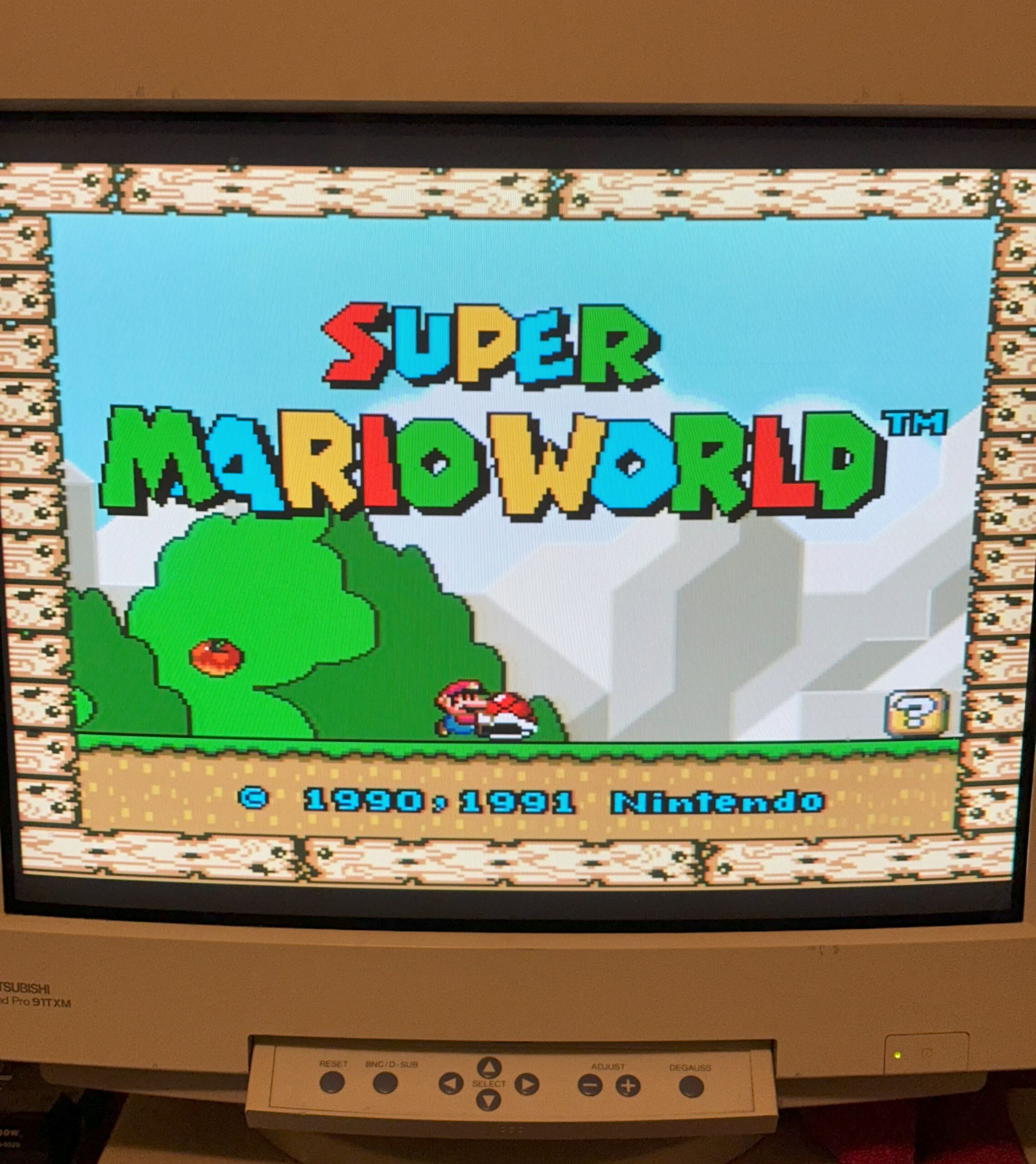
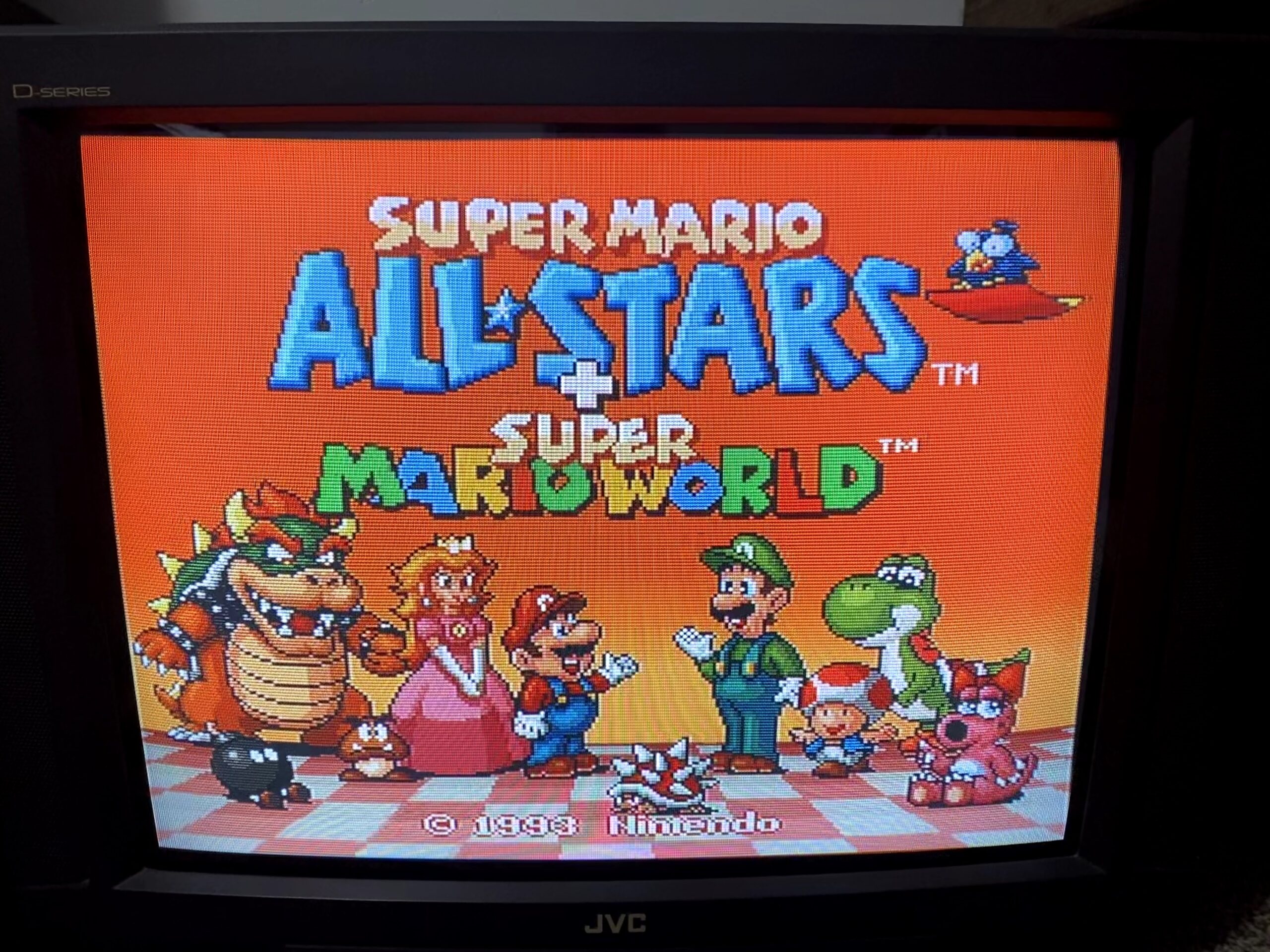
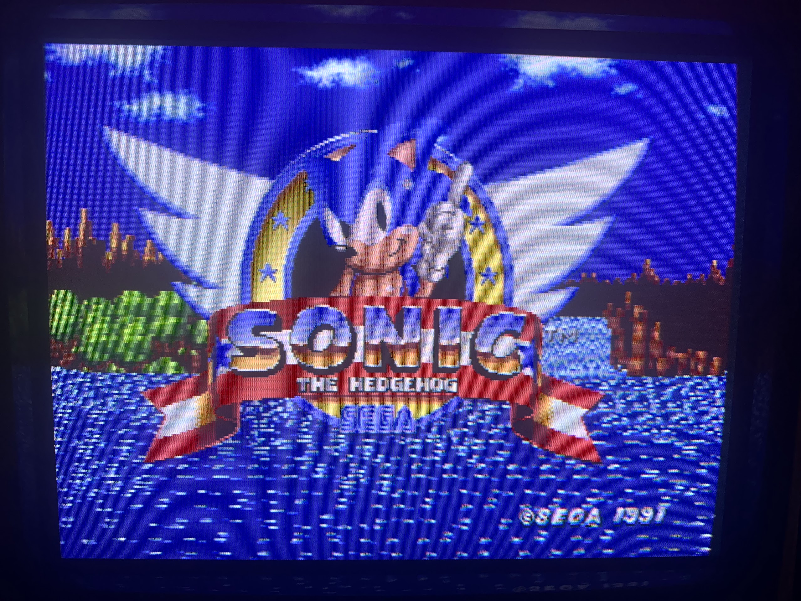
Mar 082018
 

As many of you collectors/enthusiasts may know, the FM Towns Marty is  is a  home video game console released in 1993 by Fujitsu, exclusively for the Japanese market. It was the first 32-bit home video game system, and came complete with a built in CD-ROM drive and floppy disk drive (able to read 1.2MB formatted disk like other japanese systems). It was based on the earlier FM Towns computer system Fujitsu had released in 1989. The Marty was backward-compatible with older FM Towns games :


A later model called Marty 2 was released in 1994 but it was essentially the same hardware (darker grey shell apart)

Game list includes many Japanese versions of great PC games, such as Indiana Jones and the Fate of Atlantis, Wing Commander II, Ultima VI, Monkey Island II, and so on.But this console is well known also for having many arcade-perfect ports like Splatterhouse, Tatsujin Oh, Raiden, Super Street Fighter 2, Viewpoint and other.Most of its software is on bootable CD-ROM but some games require both a CD and a floppy disk, so even if a burned CDR is used, a correctly formatted floppy is also required.Sadly the floppy drive is a weak point of this console, in best of cases the drive belt may melt over time but the unit is considered fragile and no spare are available.Luckily nowadays FDDs can be replaced by emulator and in this article I will explain how to use an HxC SD floppy emulator (by Jean-Francois del Nero) in a Marty (or Marty 2 like mine) console.

The original FDD of the FM Towns Marty console is a EME-215FS manufactured by Matsushita with a 26PIN FFC connector and cable (1.25mm of pitch) :

No info were available about so I first analized it and came to the conclusion that its pinout was the same of a slim 26PIN FDD for PC which comes with a FFC connector too but pitch is 1.00mm ( pin 13 and 21 are GND on Marty)

Based on the above pinout I figured out the connection diagram to the HxC (or a real 34 pin FDD able to handle 1.2MB formatted disks)

Obviously some kind of adapter was needed.Not having a spare 1.25mm FFC connector I ended up to remove the one from original drive and build an adapter to 34 PIN IDC (the 4 pin connector is for powering the HxC) :

I carried on the first test on a Samsung SFD-321B FDD (modified to work as Shugart drive) and it worked, I  was able to read/write/format 1.2MB 3.5″ floppies :

But I was not able to do the same with the HC floppy emulator.After some emails exchanged with Jean-Francois del Nero (a.k.a. Jeff, the designer of the HxC) we found the issue.The READ DATA signal (output from pin 30 of the HxC) was quite slow to rise up in his opinion:

He suggested me to install a 220 Ohm pull-up resistor between pin 30 and +5V (actually FDD outputs are already pulled-up with 2.2K resistors so a further 220 Ohm one put in parallel lowers the resistance to VCC to about 200 Ohm).This corrected the signal to what Marty expected to see:

Doing so finally I got the HxC flopy emulator working with my Marty console!Here are a couple of video I made during reading and formatting operation (sorry for black&white picture but my TV cannot accept NTSC signal)


As for the HxC configuration file you can set the interface on “Auto” or ” Generic Shugart” and all other settings on “From HFE”

A big thanks again to Jeff for his wonderful device and support (and patience with me too..).

 Posted by at 3:48 pm

How to use JEDutil

 Guides  Comments Off on How to use JEDutil
Apr 292017
 

JEDutil is a program included with MAME.
While MAME doesn’t directly use PAL dumps for emulation it does look to load them if they are available. As each programmer has its own output format when reading these chips (some are really different, other not so much) there arose the need to have a standard.
Read here for more information

What can JEDutil do?

It can convert a programmer usable .jed file to a MAME usable .bin file
It can convert from the MAME usable .bin file back to a programmer usable .jed file
It can be used to view the equations of any support .jed or.bin file

To see a list of supported devices you use the “-viewlist” argument

To view equations use the “-view” argument

These equations show exactly how the outputs works in relation to any given input and I believe is self explanatory to those who are looking.
Here is what the file im using for this example looks like in a text editor

You can clearly see it was created using WinCUPL.

Here is what a JEDutil created .jed file will look like opened up in a text editor

It looks very similar to the WinCUPL created file and most programmers i’ve encountered can load these without issue. One exception to that (and there are certainly others too) is the Needham EMP-20 which seems to use its own binary format that is not compatible with the MAME format.

Here is what a MAME usable binary file for a .jed will look like in a hex editor

There are clear difference between the binary and jedec files and should be easy to spot if you are not 100% sure what you have got.

Converting a MAME binary to a Jedec file
If you want to use the PAL dumps found in MAME on real hardware then you MUST convert them from their binary format back into .jed format.
You need to use the “-convert” argument

Note the filename extensions used here. The output file must be .jed (or .pla) or the conversion will fail and you will see this useful message

Converting a Jedec file to a MAME binary
To convert a .jed file into a MAME .bin file you simply use the same command but swap the filename extensions.

This will create the binary file. The original .jed file will remain untouched.

The only time I can really think of anyone needing to convert to a MAME binary is if you are submitting your dumps for inclusion to MAME
I’ve yet to ever find a use for the Berkeley PLA conversion so I haven’t covered it in here but if required it should be straight forward enough to work out.

Other Errors
Occasionally you might see some more cryptic error messages when using JEDutil. While there are things you can do to try and get around these they might also be a sign of a corrupt file or one of incorrect format.
The Jedec file format has two checksums both found at the end of the file.
The first is the fusemap checksum and the second is the transmission checksum

In the example used above the fusemap checksum is “3E71”. I believe the “C” part is always present.
The transmission checksum is “D5F0”

The fusemap checksum is the 16bit sum of all the 8bit fuse values.
The transmission checksum is a little more. Using the same example as before

The transmission checksum is a 16 bit sum of all the ASCII characters between (and including) the STX and ETX markers.

If the fusemap checksum if incorrect but the transmission checksum is correct then you will get this message

If the transmission checksum is incorrect then you will get this message

I believe you will get this message even if there is a fusemap checksum error as well.
You can disable the transmission checksum by changing it to “0000”.

In the past if I got stuck working with a strange .jed file I have loaded it into my programmers software and saved it back. This rewrites all the checksums to be correct. Your milage may vary!

There may be other errors, maybe not. I’ve not come across any other to really bother myself about.

 Posted by at 3:03 pm

ROM dumping and checking

 Guides  Comments Off on ROM dumping and checking
May 292016
 

There has been a fair bit of discussion going on in the background recently about how is best to dump ROM’s from a PCB.
This has mainly been centered around dumping with the intent of submitting them for inclusion into MAME but this still applies if you are dumping for your own reasons too.

Obviously the first thing that you need is an EPROM programmer of some kind. The selection available is massive and not really a topic this post will delve into too much.
I myself have 3 programmers available to use.
My main workhorse is a Dataman 48pro2. Its been fantastic ever since I bought it and the support is top notch too. The downside of this programmer is the cost.
My second programmer is a cheap generic Chinese programmer. The software is not too great and the English translation isn’t all that great either but it does the job nicely when my main programmer complains about voltages being out of spec or whatever.
My last programmer is a Needham EMP-20 (actually have two of these). I was given these from a local company that was having a clear out of their old unused equipment. They are really good but their downside is they are parallel port only and the software is DOS based. Apart from that they both work well.

So how do we dump ROM’s?
At first glance we think it isn’t much more than removing an EPROM from a PCB, fitting it into the programmer socket, selecting the correct device and clicking ‘READ’ in the software.
A lot of the time this is fine but how do we do our best to know that the dump was good? What if one of those old thin crusty legs on the EPROM doesn’t make a good connection throughout the read?
The result of the read under these circumstances will be, quite simply put, a useless dump of that EPROM.
Lets look at this a bit more. Say you are dumping with the view of submitting to MAME. You dump the ROM(s), bundle it up in a zip file and send it off.
Then one of the developers takes the time to add it to the source code and do some testing. Now lets say the game doesn’t work or some of the graphics are messed up.
In some circumstances, say for instance the game was a prototype or something, that developer or developers starts looking for errors either in ROM dumps or the emulation itself. Before you know it he/she has invested a few hours of their time.

The other scenario. You dump the EPROM for your own purposes. Some days, weeks, months or years down the line you need to program yourself a new EPROM because the old one has died or suffered from bitrot. You program it up and fit it but it doesn’t work. Is there something else wrong with your PCB? But what if you just didn’t dump it correctly in the first place and you never realised. You never made the dump public so any potential testers out there couldn’t even do the testing on your behalf and notify you. Congratulations, you’ve now got a useless piece of electronics on your hands.

Either way your dump was bad but we could have potentially avoided this whole mess by carrying out some really easy checks. Lets look at it.
When dumping a ROM we want to be extra sure that every time we read the device we get the same data. Every programmer I’ve ever used will display a checksum of the data dumped (although YMMV) like this.
checksum

If you read the device a second time and the checksum is different from the first time then we clearly have an issue but what if it’s the same every time? The data could still be bad so let’s try physically removing the device from the programmer and reinserting it then trying to read it again. Is the checksum still the same? If not then we are probably going to need to investigate further. If they are the same then how about we remove and reseat one more time just to be sure. This may sound like a waste of time but the reality of it is it only takes a few seconds for older EPROM’s to be read out and it could potentially save everyone a lot headache further down the line.

So now we have dumped the ROM (three times) and we are happy that no matter what we do or how we position it in our programmers we get the same dump each and every time. What next?
In the case of an arcade PCB let see if the dump we have compares to anything already dumped and included in MAME.
For this you will need the latest version of MAME available from MAMEDEV
Open a command prompt at the directory where you unzipped/installed MAME and type ‘mame -romident [YOUR-ZIPPED-FILES-LOCATION]’. If you use the 64bit version then type ‘mame64 -romident [YOUR-ZIPPED-FILES-LOCATION]’ instead.

Here is an example using the rbisland romset. I’ve added a random binary file to show what happens when an undumped file is found.
romident

What this shows is each individual file within the .zip file and the filename associated with each other romset.
The “9100.bin” file is the undumped file and you can see it shows “NO MATCH”. This means that the file is unknown to MAME.

If they are all matched then nothing more needs to be done. If they aren’t a match though then we could be looking at something undumped OR we could still be looking at a bad dump.

Included in the MAME package is a tool called ‘ROMCMP.EXE’. This is another command line utility that performs a variety of checks on your files. For example it will tell you if the dump is all 0xFF bytes or if the top and bottom half of the dump are the same. It can also be used to compare your files against the files currently in MAME to see how much of the data matches.

To use this tool we need our file or files in a .ZIP file.
For this example I( have used the Major Title 2 romset ZIP file and have added an extra binary file which I hand made but made bit 1 (second bit) stuck on using a hex editor.
romcmp

The output is simple enough to see. It shows that bit 1 is always ‘1’.
If you have dumped what you believe is a new ROM set then you can use ROMCMP to compare against an existing set.

Here I used two different sets of Major Title 2 to demonstrate.
romcmp2

You can see most files are identical but there are two that aren’t quite the same (these two are the main program ROM’s for Major Title 2). You can also see that they are both over 80% the same as each other. This is a good sign for a different revision of the same game especially as we have already done the previous checks on the ROM’s to confirm their validity as much as possible.

There may be other steps that people like to do on their ROM dumps but the above will give people, whether its yourself or an emulator developer trying to support it, a fighting chance.

 Posted by at 12:20 pm

Using a lightgun with Operation Wolf PCB

 Guides  Comments Off on Using a lightgun with Operation Wolf PCB
Apr 052016
 

Some days ago I received an Operation Wolf PCB bought from Hungary.After dumped ROMs and comparing the board layout with pictures on the web it turned out to be a rare prototype which runs unprotected code (it lacks of the C-CHIP IC).I suggest you to read the whole story on David ‘Haze Haywood ‘ homepage:

A Wolf in Prototype Clothing

After adapting the board to JAMMA, I fired it up and it was perfectly working.Reading on the Web,  there are conflicting opinions if this board is a simpe lightgun game or it uses analog joystick like some many people claim.So I wanted to try myself and bought a couple of cheap Happ lightguns widely used on games like Lethal Enforcers :

happ_gun

All lightguns work in the same way: you’re pointing your gun at the screen, and the gun is essentially a light sensor.When the part of the screen which the gun is pointing at gets flooded in white, the sensor detects it and sends a signal to the game: “I can see white now, I’m pointing at the part of the screen you’ve just drawn”. At this point the game can work out how far down the screen it has drawn, and how far along the current line, which gives a pretty accurate position of where the gun is pointing.

The Happ gun has a 4 PIN connector and looking at Lethal Enforcers schematics, this is the pinout:

happ_gun_connector

The ‘HIT’ signal (so called in Lethal Enforcers but name is relative) is an input on arcade PCBs and it’s essentially the output of the optical sensor (a phototransistor) mounted inside the gun.The ‘TRIGGER’ is the switch inside the gun and it’s shorted to GND everytime, indeed, you pull the trigger.VCC and GND are obviously needed to power the electronics inside the gun.With this info it was very simple to adapt this gun to the Operation Wolf PCB.The pinout of this board shows ‘TRIGGER’ signal on pin 21 parst side of ‘G’ edge connector on main board and ‘HIT’ (called ‘SENSOR’ in service manual) on pin 5 solder side of the ‘T’ edge connector on sound board:

SENSOR_TRRIGGER

For a better interfacing of the gun to the PCB I used a 4 pin right-angle male header mounted on a piece of veroboard:

4_pin_header_Operation_Wolf

Lastly, since Operation Wolf use another input for rocket and this Happ gun lack of a second switch, I added a further button (a normally-open one)  mounted inside the gun and connected to internal common GND and ‘ROCKET’ signal which is PIN 4 of the ‘M’ connector on Operation Wolf main board (but if you want, you can also adapt a PSX/Saturn Guncon which comes with more than a button)

rocket_switch


M_connector_pinout

Finally now for sure I can say that Operation Wolf is a simple lightgun game.So let’s go to play it!

 Posted by at 11:33 pm