Dec 252017
 

In the past, every time I’ve undertaken a ROM hacking project i have ended up with a cluster of binary files all at varying stages of usefulness. This simple program is how I will now be working with binary file hacking.

The format of the changes is really simple and can all be put together in a text file or in the program itself.

As you can see, comments are supported.
Using this I can comment the changes I make and just ‘Autopatch’ a binary file after I’m finished and if I make a mistake then I can modify the text file and reapply to the original binary.

I understand that the way I approach things is not necessarily the way most other people approach things but it might be of some use to someone else out there.

The software has a simple HEX viewer in it, can byteswap the loaded binary and also supply an offset.
The offset is relatively untested and is intended to be used if you are loading a ROM file that normally starts at, for example, address $1000 in memory space. You can apply the offset and write values to the correct addresses. If in doubt then just avoid this altogether as it will cause problems and cant really do any error checking.

Merry Chistmas

 Posted by at 3:57 pm
Jul 272017
 

Recently I’ve been working on some Windows based software to use the Data I/O 29 series programmers.
Its coming along well and I have a few people willing to test things out for me which has been great as its a pretty tedious task of trying things out and reporting back, rinse and repeat.
I captured a small video showing some progress.

The programmer itself isn’t all that hard to interface with as most of it is just issuing commands which are all outlined in the manual but there are a couple of things to deal with when it comes to uploading a file to the programmer.
I’ve also been collecting ID codes for programmers and modules so I can auto detect programmer and more importantly the module that is fitted. This allows me to auto populate a device list.
Ive tested this using a cheap USB to serial adapter and its been working fine.

 Posted by at 9:08 pm
Apr 232017


Its hard for me to believe that i’ve been maintaining this program since 2011.
I’ve added to this as I needed extra functionality and for the last 12 months or so its been untouched but for the last few weeks I’ve been rewriting some parts I wasn’t happy with and changing a few things around.
Its now got to the point where I think its pretty much complete (although i’ve said that before) so though it was about time I did a proper post on some of the things it does and how to use it.
I wont go into everything as I dont think I need to but let me know.

What does it do?
Back when I started this program I wanted a quick, easy and no fuss way of quickly interleaving, deinterleaving and byte swapping files. That’s exactly what it did but that’s all it did.
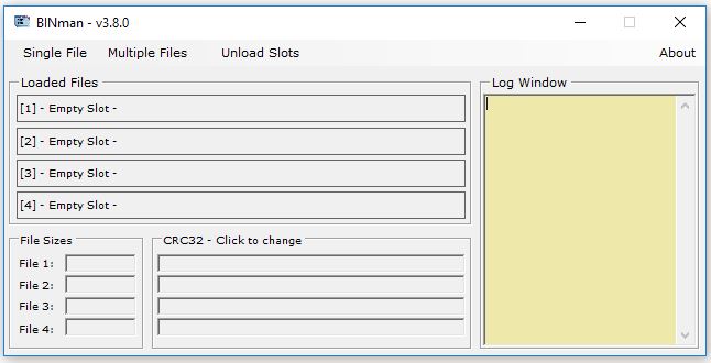
Take a look

What it does now:

  • Create a new files filled with recurring byte or word values
  • Analyse a file (8 bit or 16 bit) – check for stuck bits, upper and lower halfs matching, etc
  • Bit manipulation – simulate stuck bits in a file & swap bit order of address and/or data bus
  • Byte swap
  • Deinterleave
  • Invert the whole file
  • Manipulate – XOR, swap bits, simulate fixed bits
  • Reverse the file
  • Split the file in to smaller files
  • Swap the upper and lower half of the file
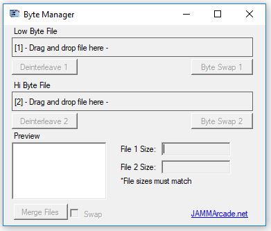
  • Concatenate up to 4 files at once
  • Interleave in 16 bit, 32 bit  or 64 bit format
  • Compare 2 files – checks how many bytes match
  • Display CRC32, SHA1 and MD5 hash values

Creating a new file
Click the ‘Single File’ menu and select ‘Create a new file’
You should see this

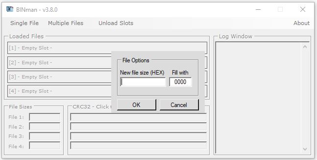
You can fill the new file with a byte pattern or a word pattern.
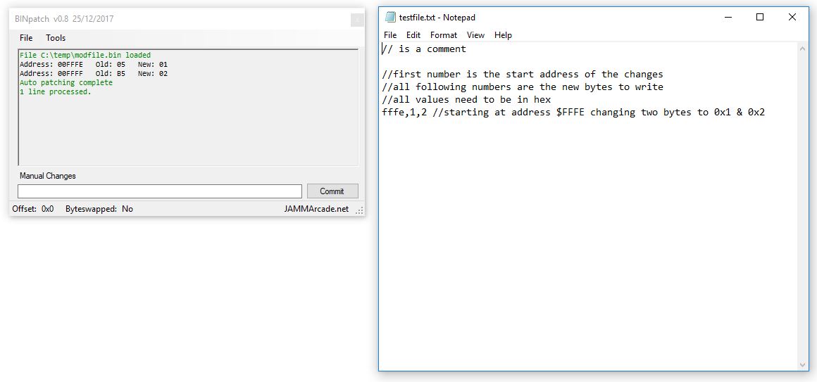
To fill with a specified byte pattern you can enter something like this

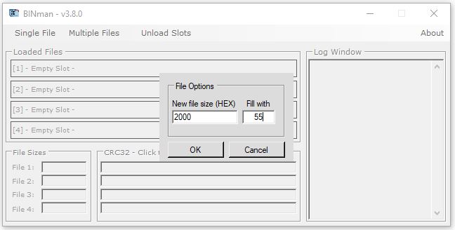
This will fill each byte with a value of 0x55
To fill with a word pattern you will enter

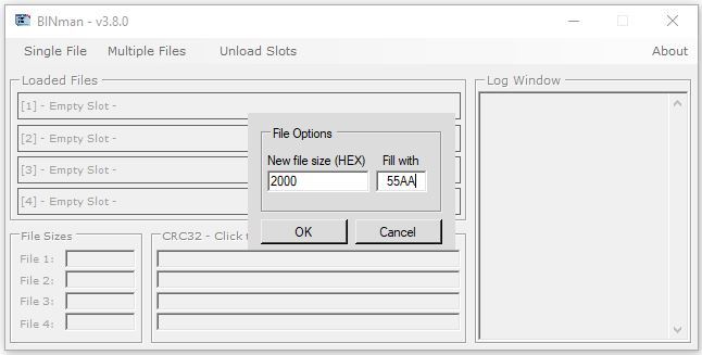
This will fill the file with the word value 0x55AA

If the slot is empty you can also load a file by double clicking on the slot.
You can overwrite any loaded file by dragging and dropping a new file onto the slot.

Analysing a file
Analysing a file check for a few things.
First you will need to select from the menu whether the binary file you loaded is from an 8 bit or 16 bit source.
The output from the analysis will be displayed in the Log window.
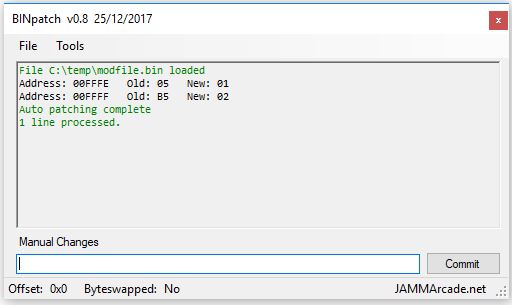
In this example I have created a new file filled with 0x0

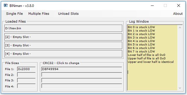
As you can see it has flagged up all the bits (8 bit) as being stuck LOW. This means that throughout the file non of the bits changed from logic state 0.
It also shows that the upper and lower half of the file are filled with 0x0. If the file (or half the file) was filled with 0xFF then this would be flagged instead.
Finally, we have flagged up that the upper half of the file is identical to the lower half of the file.

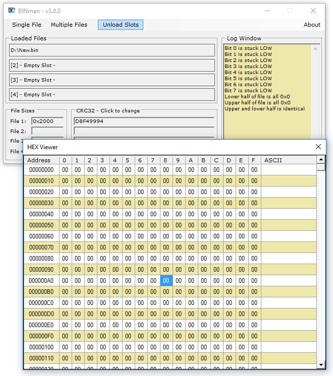
Viewing the file contents
There is a basic HEX viewer built in to the program. Just double click on any of the loaded slots to view it.
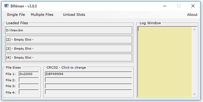
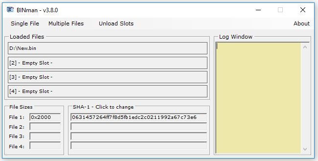
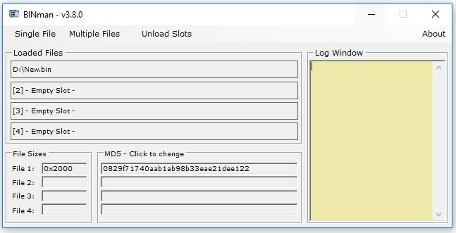
Checksums
There are 3 different checksums that the program can show you.
The default is CRC32 but by clicking on the “CRC32” box you can cycle between CRC32, SHA-1 and MD5.
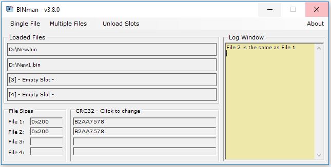
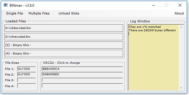
Compare files
If any loaded file is the same as another file that is already loaded you will get an instant notification in the Log window that is matches

If however the files are not a match, its sometimes nice to see how much of the file actually does match. For example, if you have a a new revision ROM dump of a game you might want to see how much has actually changed. If its just 1 byte different then it could be bit rot or a region code change.

I think the rest of the functionality is self explanatory so wont go into it.
The program is in the software section now.
Please do let me know if you find this program useful, find any bugs or maybe want to see something added or changed (no guarantees though).

 Posted by at 2:21 pm

GameKing multicart

 Projects  Comments Off on GameKing multicart
Mar 122017
 

I seemed to be one of the first to get the ball rolling with Gameking dumping.

I had to make my own part for the cartridge connector. This allowed me to make the breakout PCB.

This worked well enough for my dumping needs but I also wanted to test the dumps on a real Gamking. This led me to the first cartridge test. It has a bunch on things on that weren’t really needed but I was just playing about with ideas at this point.

It sort of worked but would do with some refinement.

This one worked much better but after dumping some 4in1 cartridges we found they didn’t always work properly using the homebrew cartridge. This led to the analyser PCB.

I never did get hold of any 4in1 carts myself so thats as far as that project actually got, although I don’t think its required anymore.

The final product is this cartridge. I believe one of these was used to aid in dumping the internal ROM.

It works fine for single games and a few 4in1 titles.

 Posted by at 1:03 pm
Mar 122017
 

This has been my main project for a long time now. Its something I started initially on the ABI Boardmaster 4000 as simple pin toggle routine. This allowed me to toggle the logic states of any pin and get a live update of the state of all the pins.
When I first got my Arduino MEGA I decided to port the program over to that as my first project.

PIN TOGGLER

It ran through a terminal window and was pretty much identical to the BM4K version I made.
It has a jumper on the board to switch power between 20 and 24 pin devices.

Revision 1

From this point I wanted to have a Windows GUI so I could have a graphical environment when using my ‘pin toggler’.

I also moved to using the ports of the Arduino to speed accessing up so with this in place I added the ability to brute force the operation of the chips so Caius could recreate 24 pin devices. The method used was identical to the way Charles MacDonald’s device worked so to keep compatibility with his analyser program. I don’t really require the ‘dumping’ feature of this as I use the hardware from Charles and its a lot faster to use but this option is there if I ever need it.
There were a couple of other things I wanted to add too from a hardware point of view. I added two reset buttons to the ‘shield’. One was to reset the Arduino itself and one was to reset the PAL/GAL in the socket. The jumper was still present on this revision to select 20 and 24 pin devices.

Revision 2

Not too long after revision 1 I decided I wanted to be able to control the power to the chip from the software. As you can see the jumper is gone and got replaced by a couple of transistors and resistors. Using this setup I could easily select 20 and 24 pin devices using software. I don’t think there were any other changes here.

Revision 3

This is where things started to gain momentum within the project. I spent a lot of time changing the software for this one.
So the hardware had a couple of obvious changes. First was I added LED’s to show which device type was being used.
Second was the socket itself. I had bought a ZIF socket for the project but it had 0.6″ spacing so in order to let me select between the two should I need to, I added both to the layout

The software got a big update this time around with many things being rewritten.
Myself and Caius had started to realise that there were quite a lot of PAL’s out there that used latches. Latches can be implemented in a non registered IC by using the feedback from an output pin. In some cases we haven’t even realised that latches were being used and it was only later we found out when people raised an issue.
To check for latches I added the ability to dump the PAL backwards so instead of counting the applied address up it counted down. It performed a forward and reverse operation then compared the results. If they were a match then it was a good bet that latches weren’t being used. I also added the option to use random addresses too which would give a more thorough test but took a lot longer to complete. I have never really needed to use this so far.

Revision 3a

This revision moved to surface mount components, removed the ability to use 0.3″ space ZIF socket and also added extra resistors. The resistors on the input only pins were there for protection in case of shorts.
Aesthetically, this one had rounded corners.

The software added support for those 20 pin devices that had an extra IO pin at pin 9 like the PLS153 and GAL18V10 although the supporting analyser software didnt support this so it never got used but it meant the pin toggle part of the software could use it.

Version 2

So here we have Version 2. All the previous iterations were what I called version 1. This one never turned out as I had hoped. I moved away from using ports on the Arduino which was a massive mistake. I did gain complete flexibility though. I had been studying some strange devices with a non standard IO configuration. This was going to be my of dealing with those devices. Unfortunately it became painfully clear that my software was so rigid that it didn’t allow changes to be easily made.
At this point I decided to rewrite my software from scratch opting for more of a suite environment for all this PLD rather than a simple bit of software.

The software as it stands right now is my proudest creation. It has GUI’s for MAME’s JEDutil and Charles’ analyser program and also the commandline version of WinCUPL too allowing everything to be done in the same place easily. It can also be set to automatically analyse a ‘dump’ and compile to a fusemap.

That’s where this project is right now. I’ve not finished with it yet but its not actively being developed either.
Hopefully I will get back to it at some point but at this moment there isn’t too much need

 Posted by at 12:45 pm