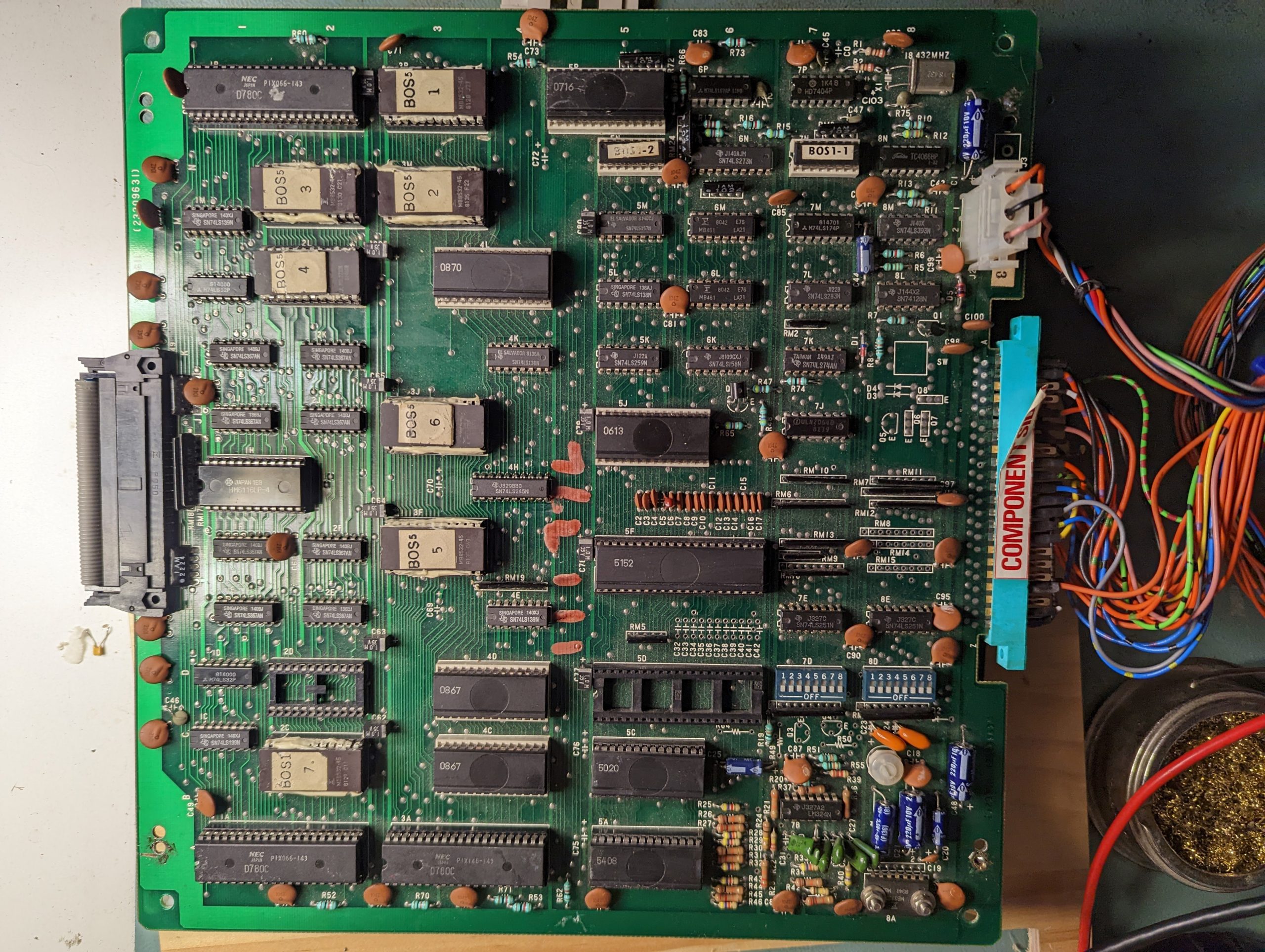
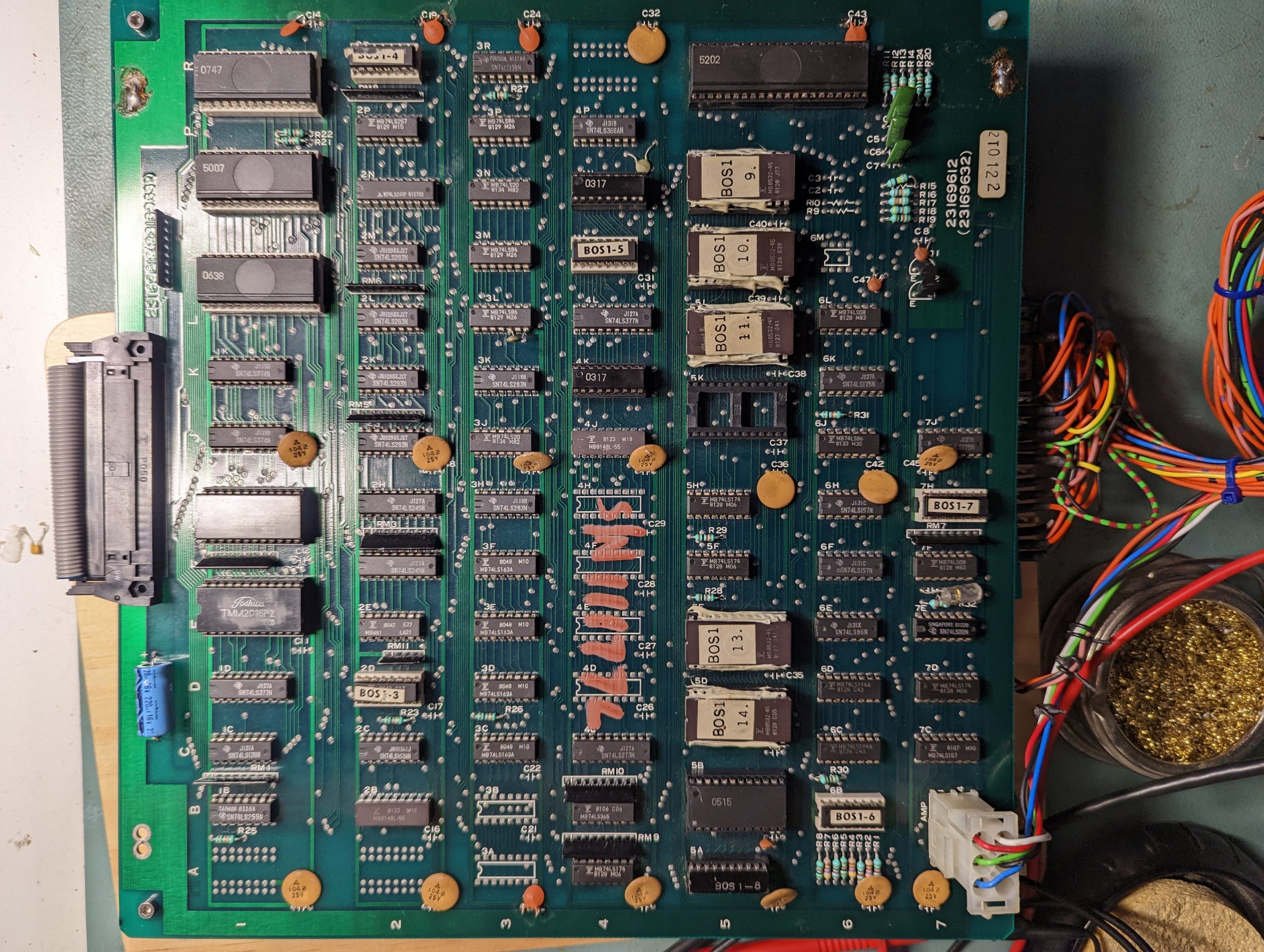
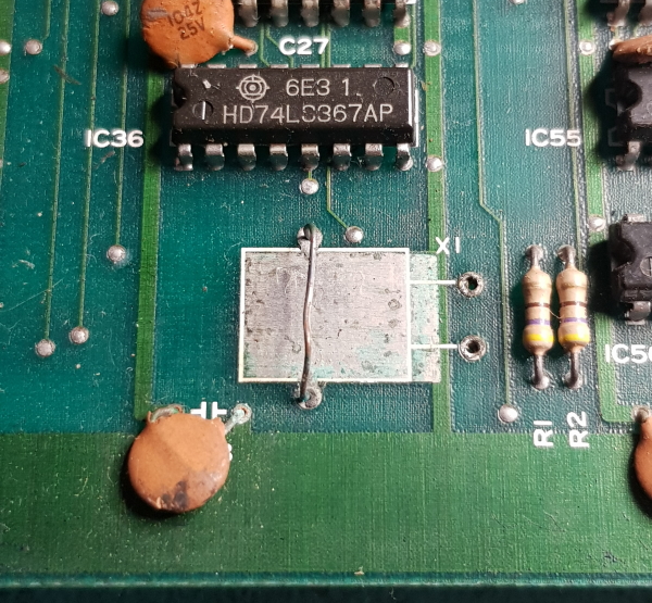
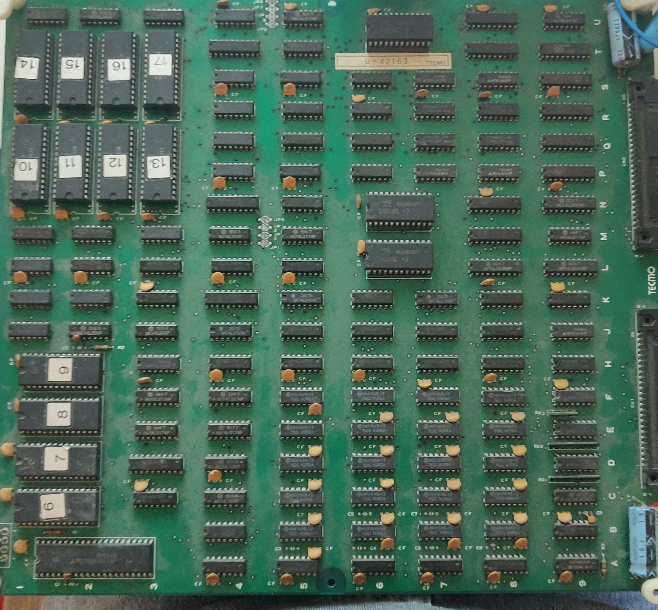
Board is a bit dusty but very clean nonetheless. Some very specific chips are rusty, probably due to some rodent fluid. Tracks are invisible and located in the core of this 4-layer board making the inner tracks very fragile when pulling a chip out.
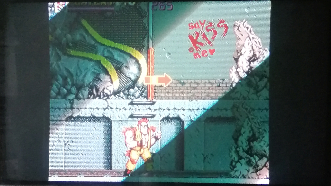
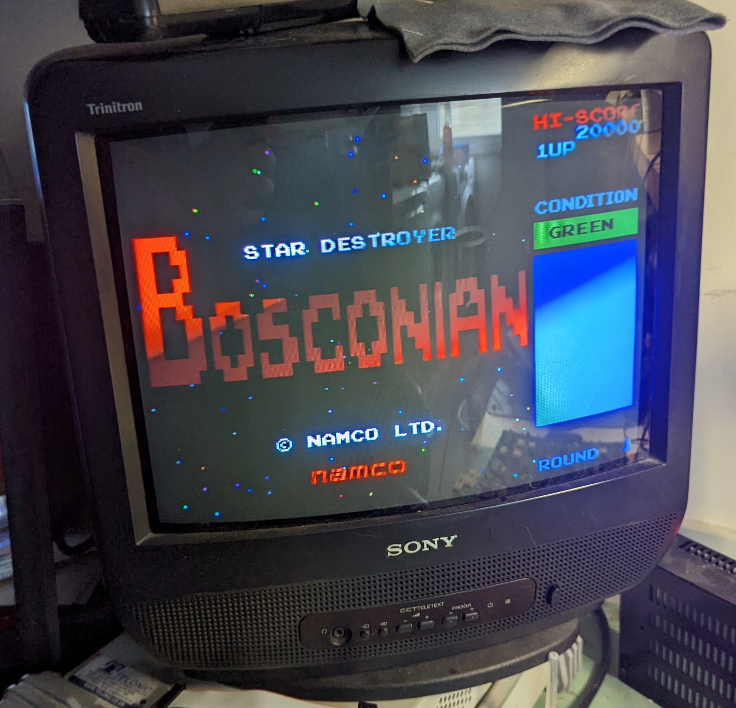
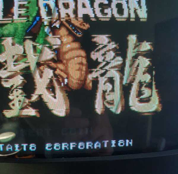
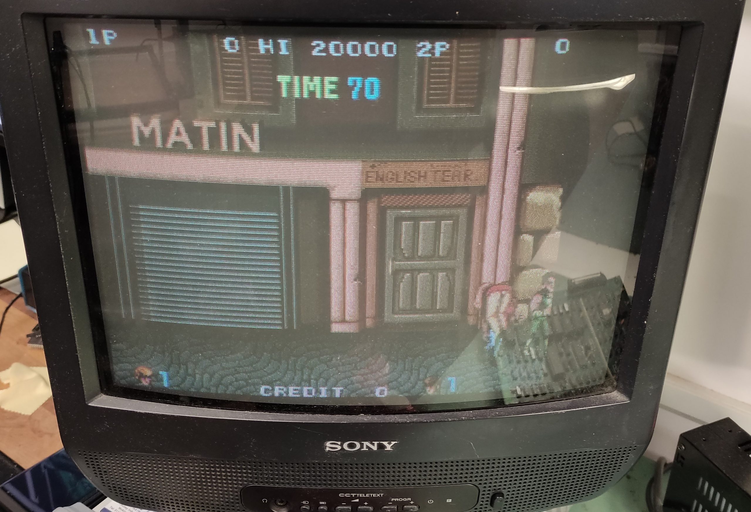
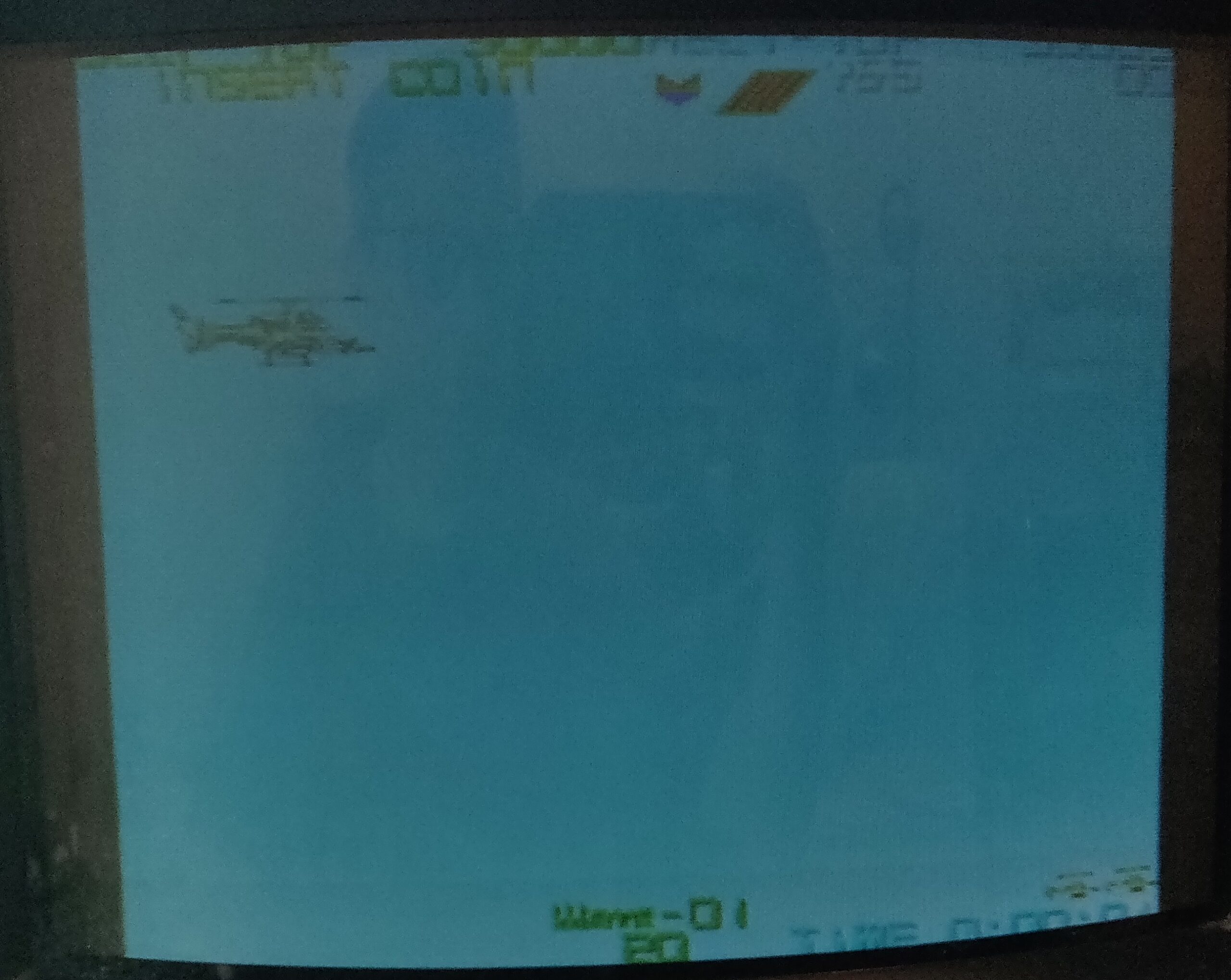
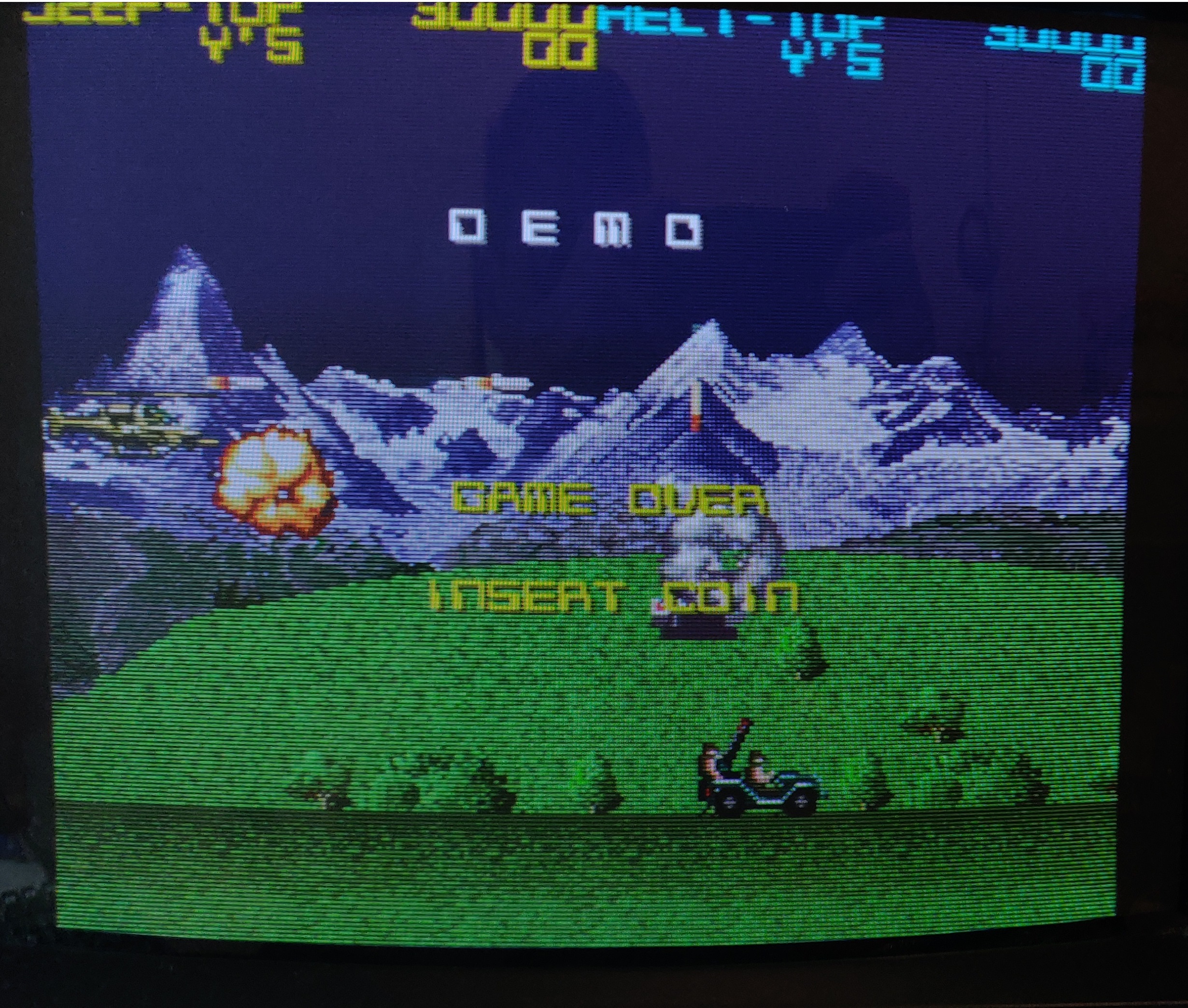
Game starts when powering the board with full sound and some graphics. The title screen has a white background instead of black as it should be. A similar white background appears during attract mode:
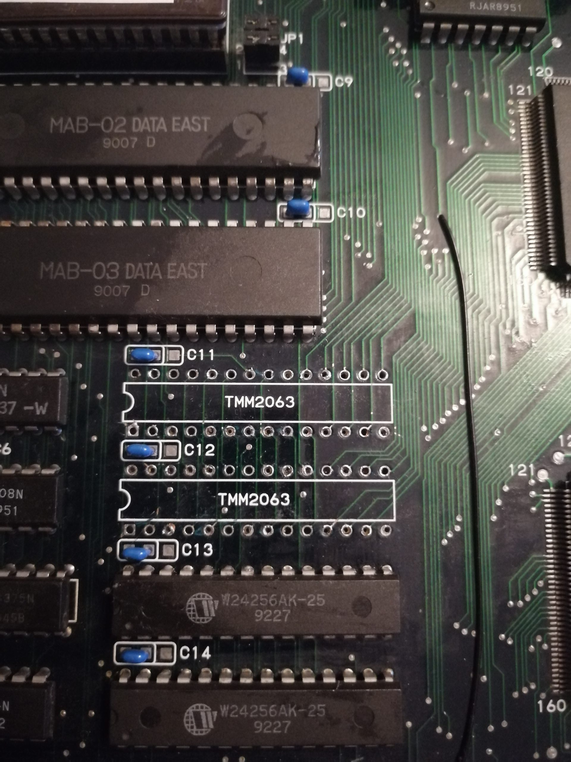
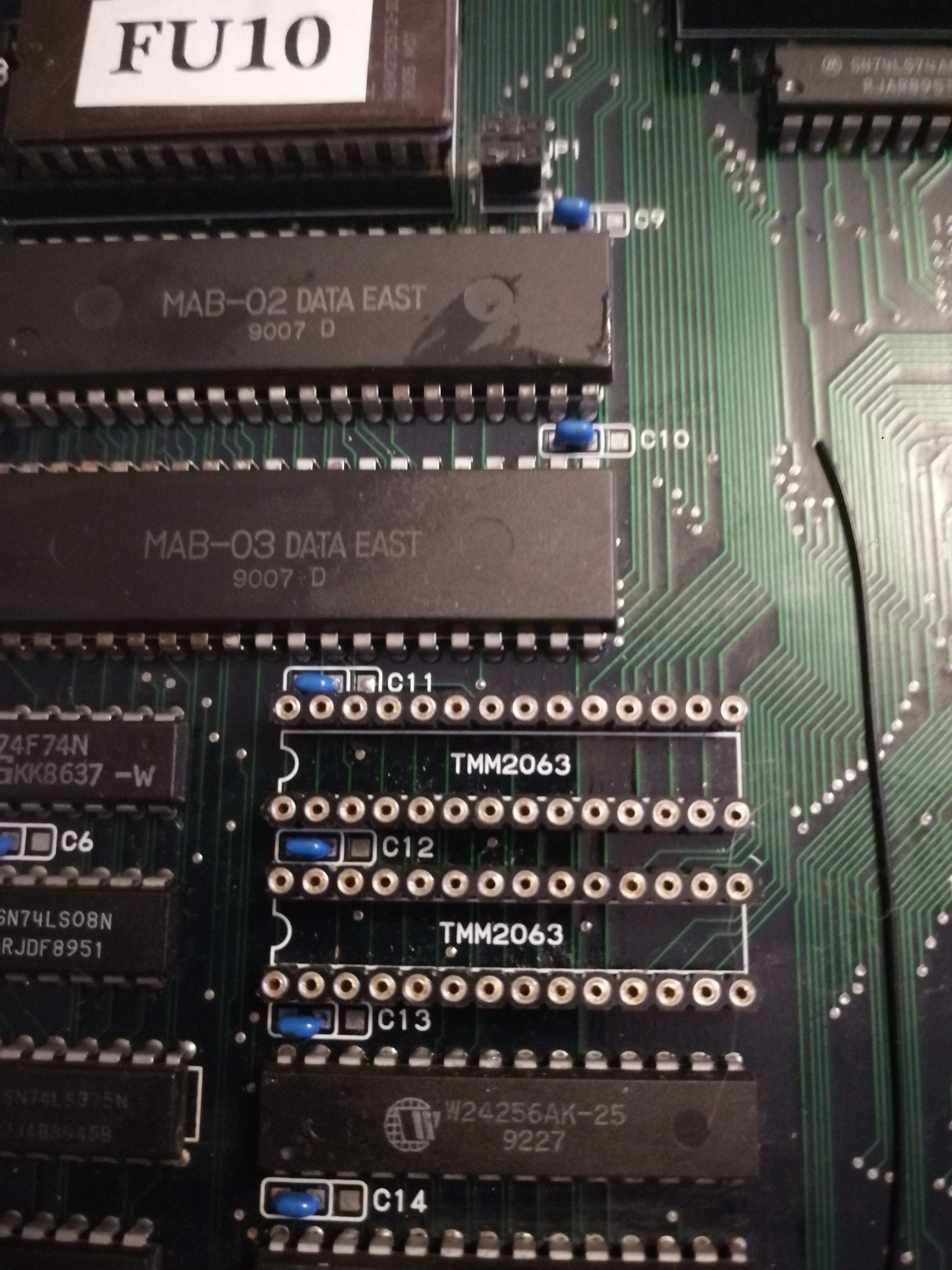
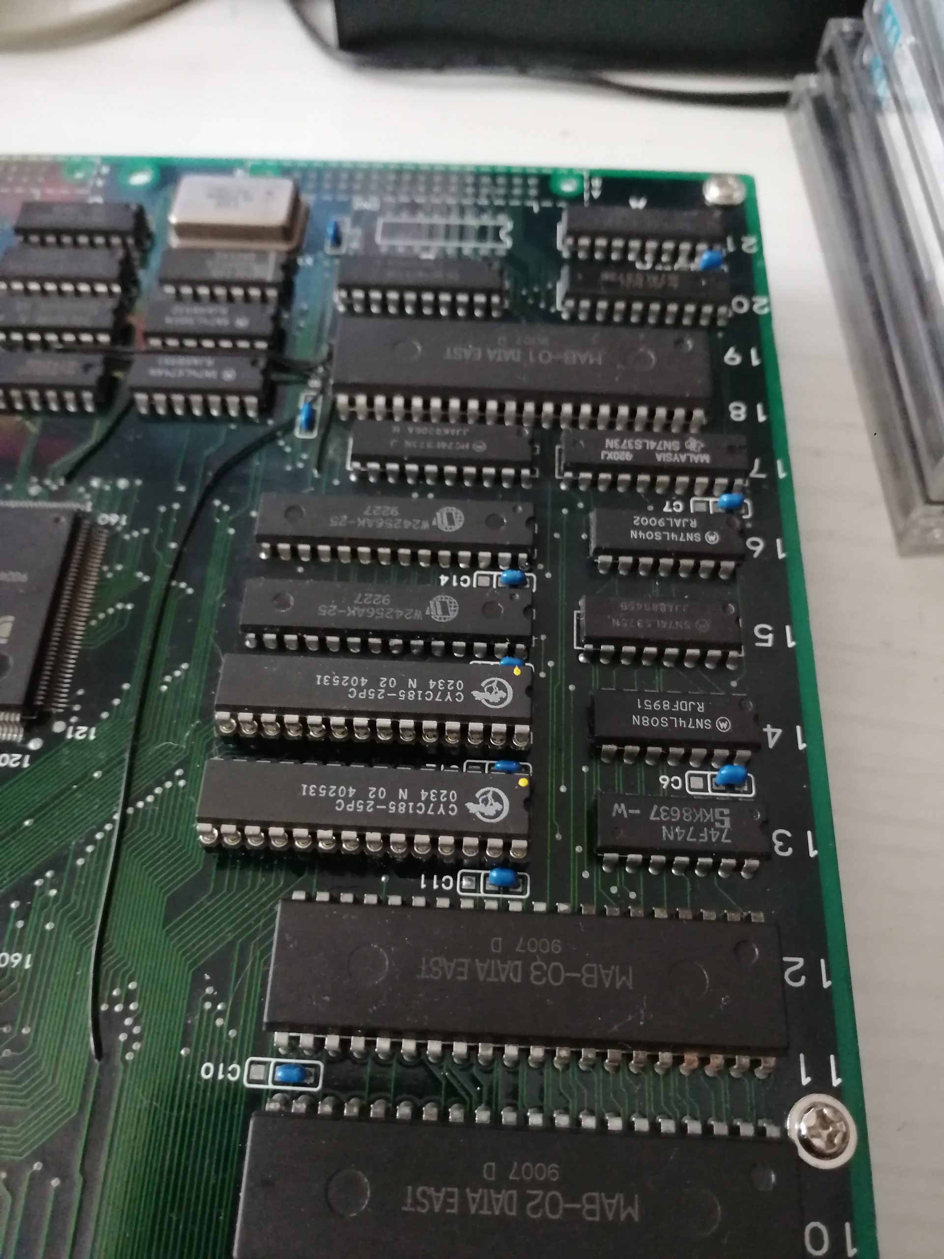
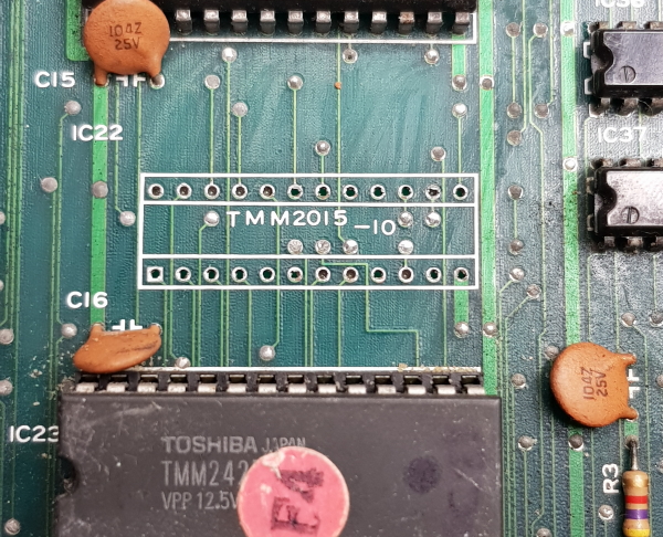
Cross-testing the board with a good one points the fault to the bottom board (graphics board). On this board I started probing the 8 EPROMs filled with the background graphics data. Some pins are quite corroded, so I decided to dump them to check their contents against MAME data:
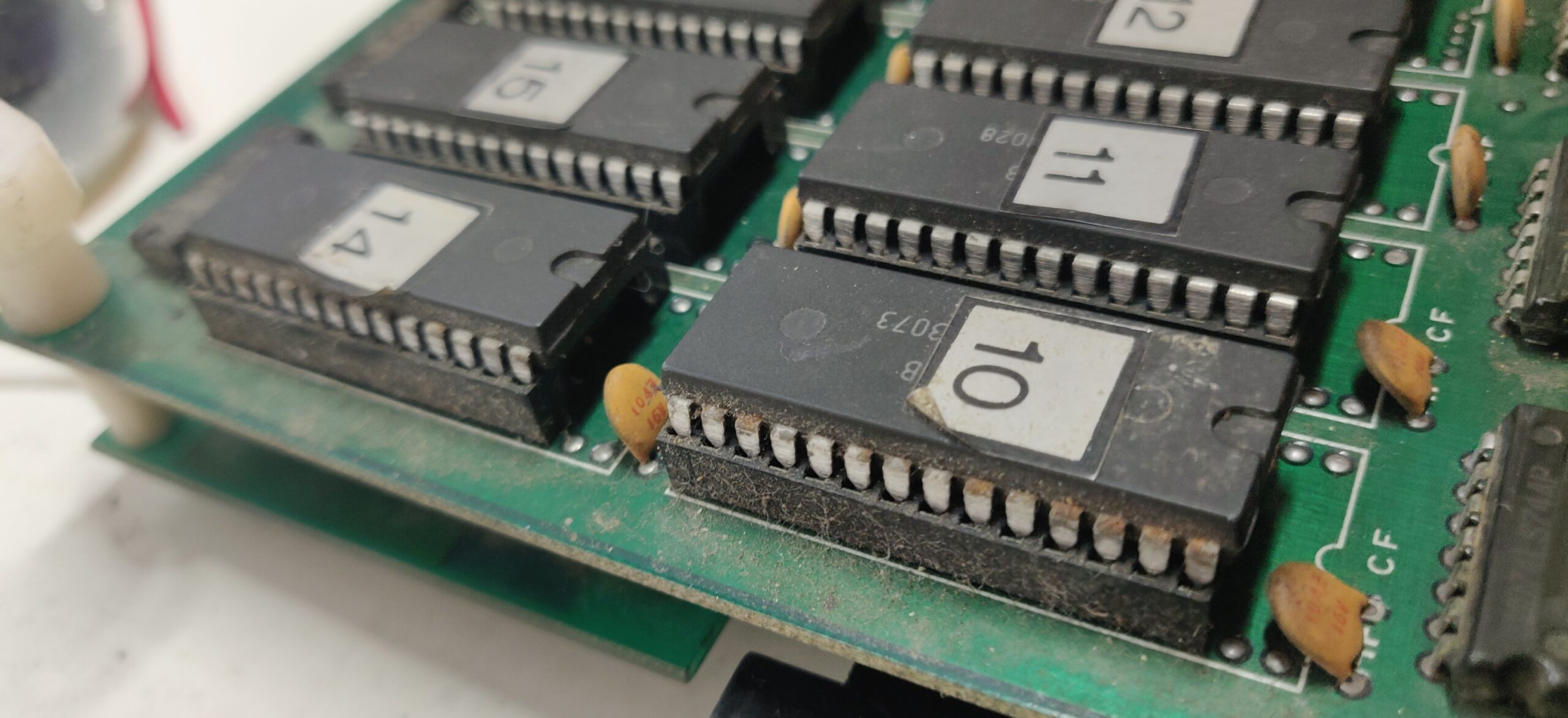
As a result, EPROMs 10 and 14 are dead. I burnt two replacement EPROMs and that brought the background back:
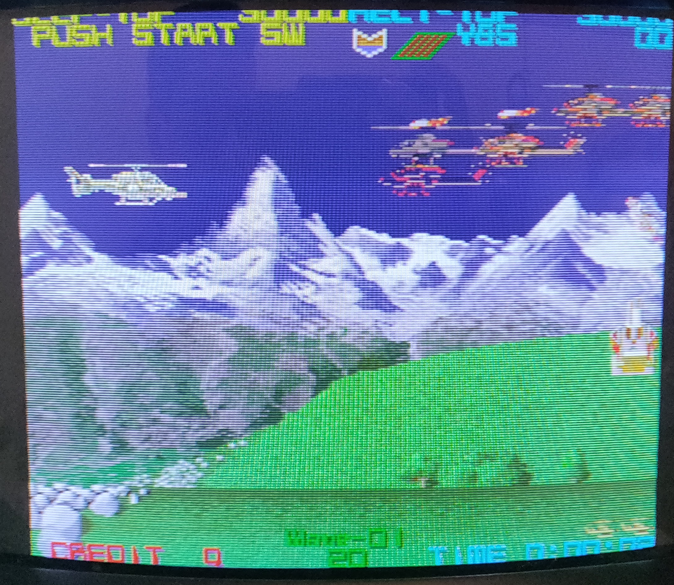
Background is back but the sprites are blinking, they are misplaced and have bad colors. Sprites are generated by the custom chip Mitsubishi M60002-0118P and displayed through twenty 4164 DRAMs. These are known for having a high failure rate. I will focus my investigations in this area:
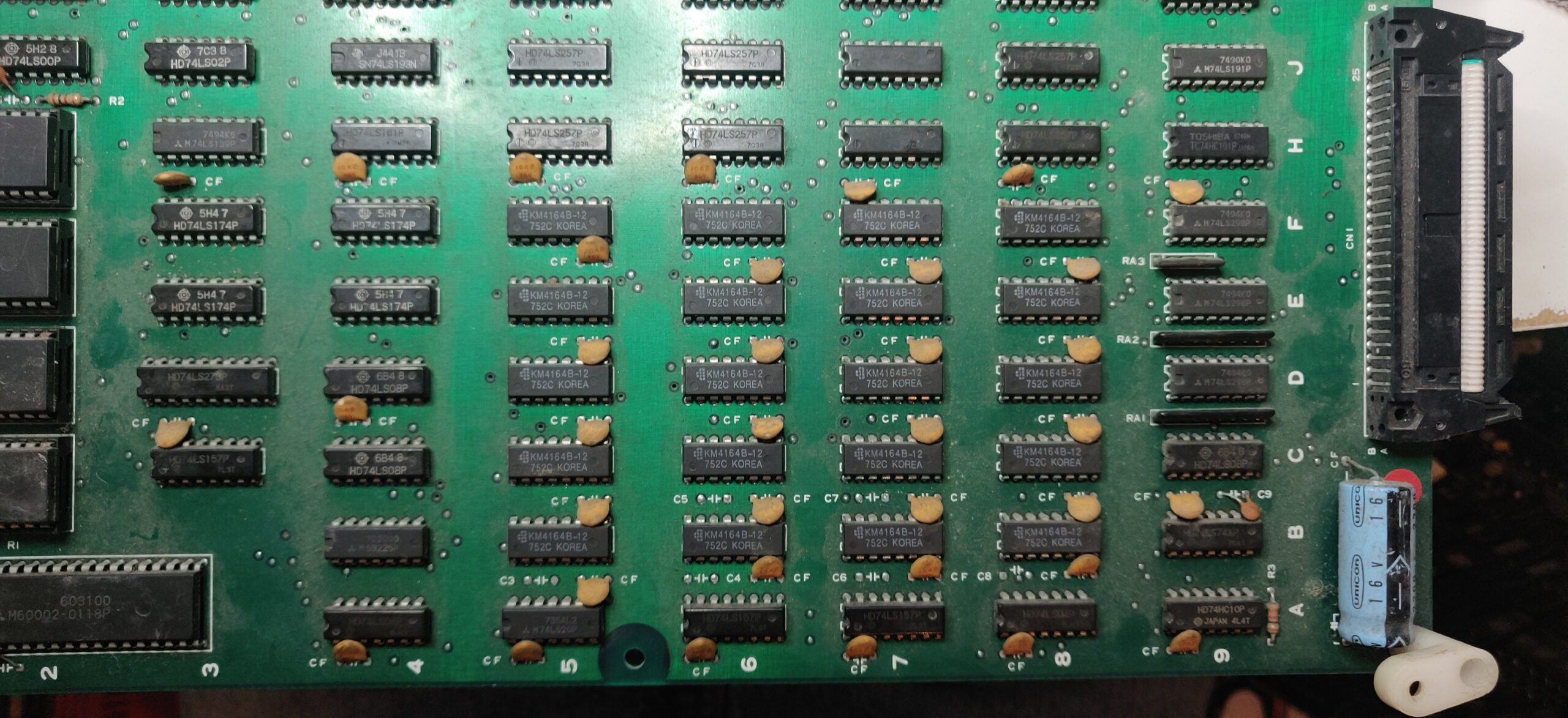
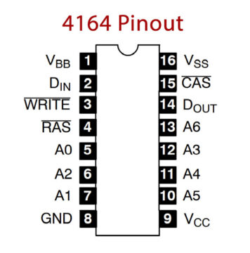
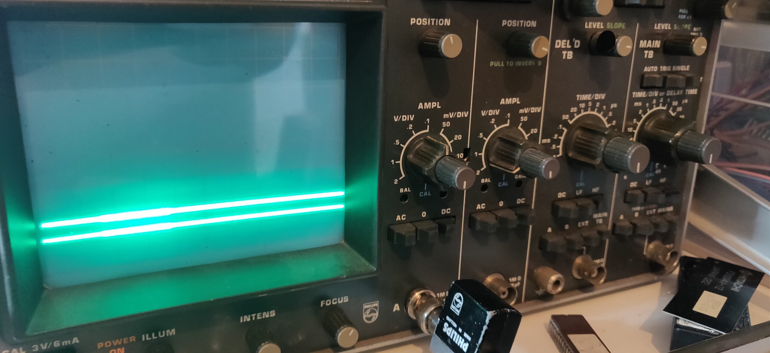
Probing the D-OUT pins of these DRAMs (pin 14), 8 DRAMs out of 20 shows an output signal stuck low or even floating when the game has to display sprites:
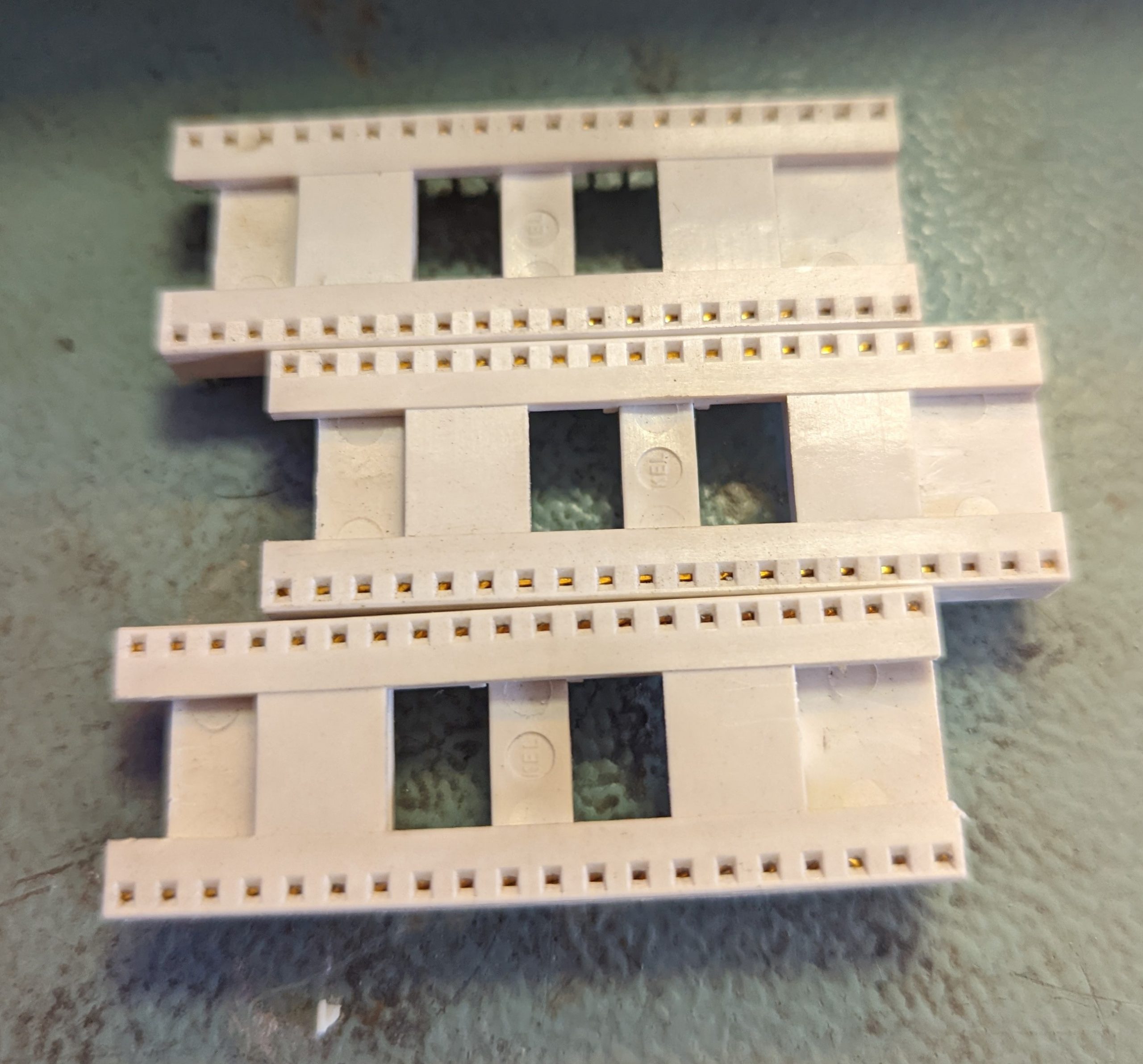
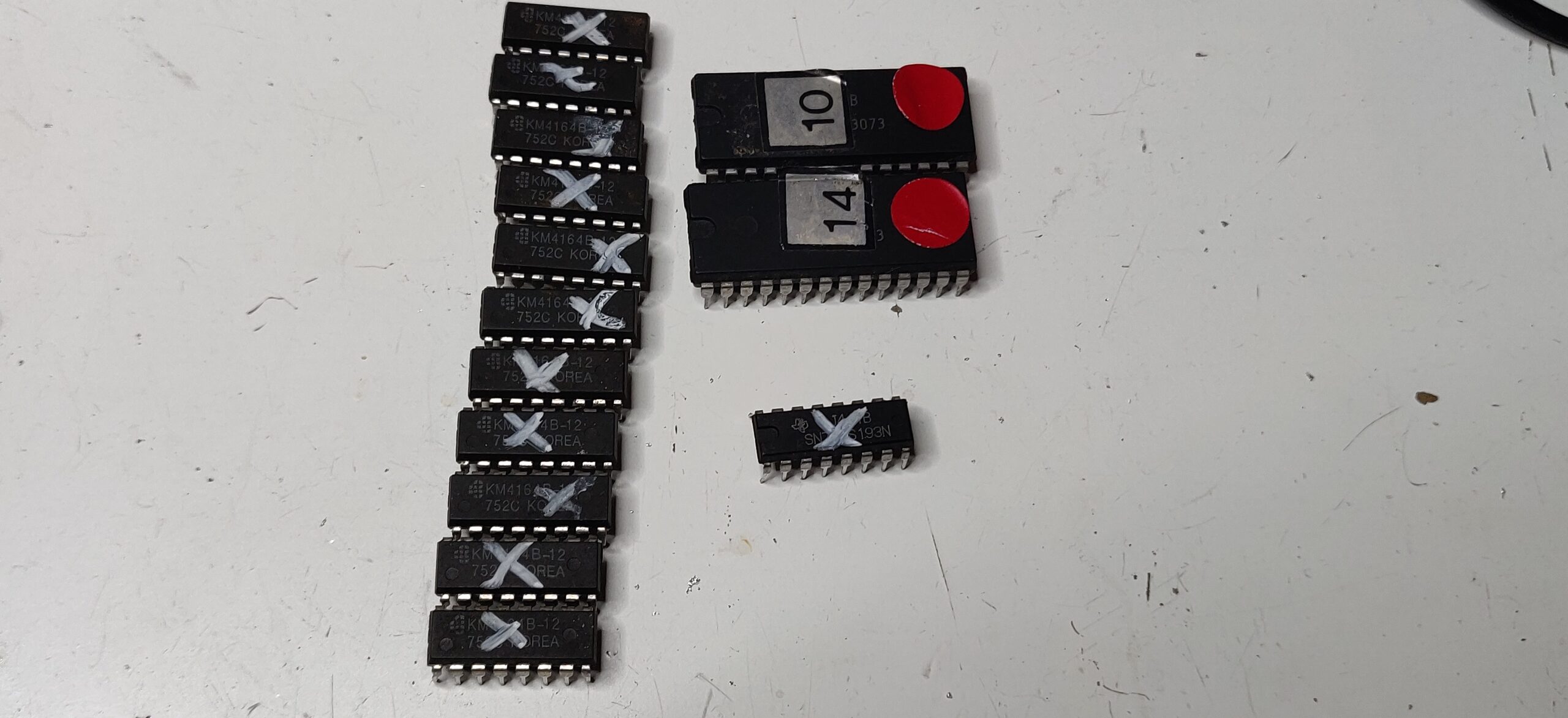
I pulled these 8 D-RAMs:
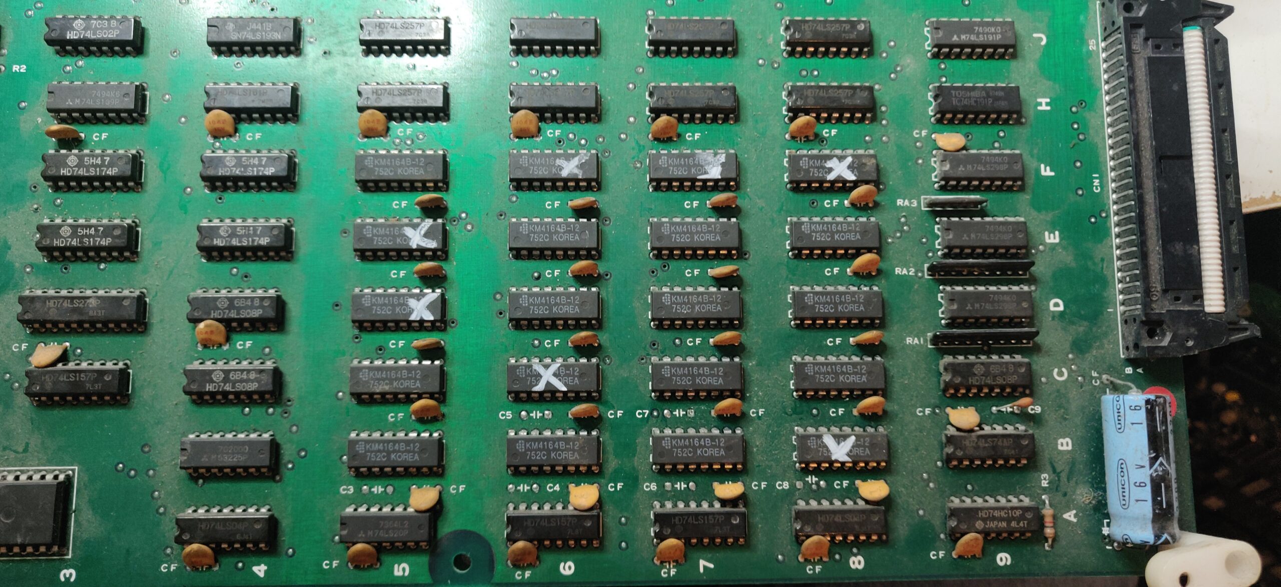
All of them were confirmed bad out of circuit.
I fit 8 brand-new replacement DRAMs. Some sprite glitches are still visible – two other DRAMs have just gone bad. I took those out and replaced them. Now the sprites and backgrounds appeared to be rendering properly. However, the sprites motion is still jerky.
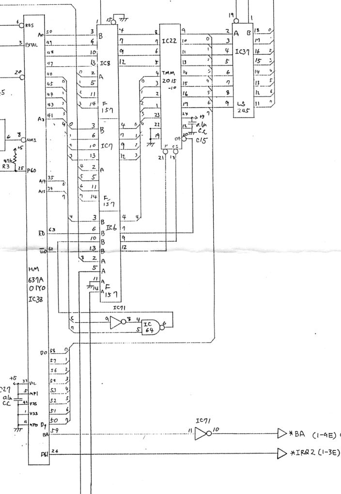
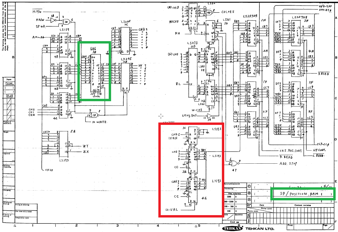
Rygar shares the same hardware as Silkworm and has schematics available. In the schematics, we can see that two 6116 SRAMs handles foreground and background graphics and a third one is dedicated to sprite positioning (SP/POSITION.RAM as per the schematics). This is the area I will inspect.
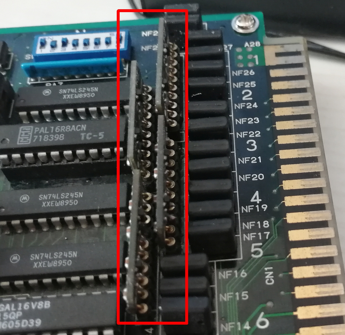
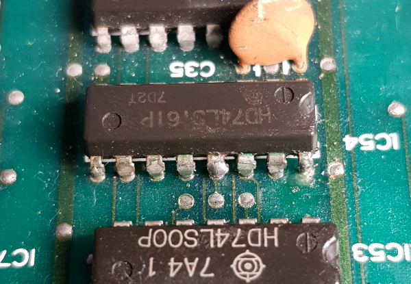
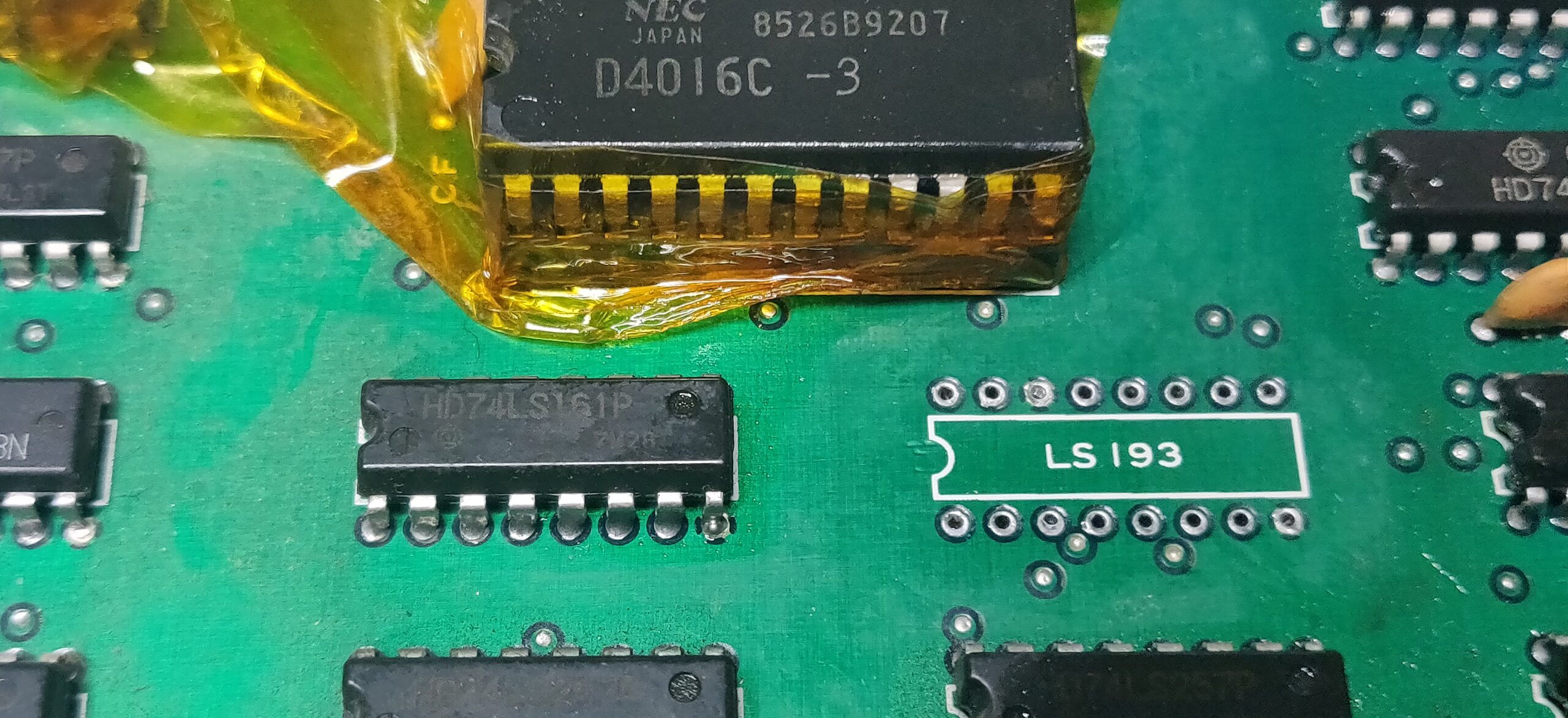
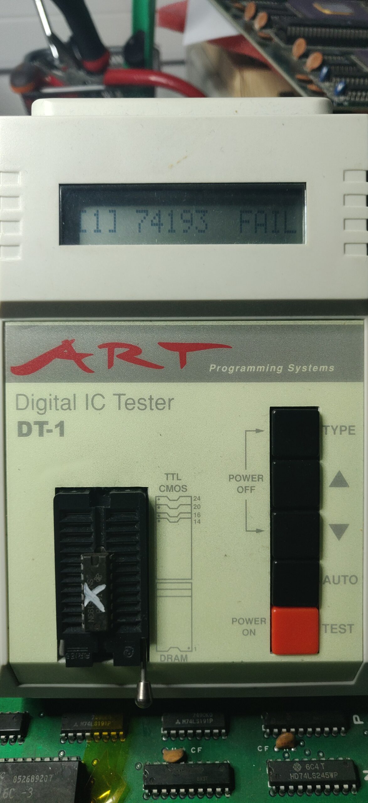
Inspection of the SRAM chip at location 6L doesn’t show anything abnormal. While probing around the area, I came across a signal stuck high on a 74LS193 binary counter (BORROW output) located at 7K. I double-checked it with my logic comparator:
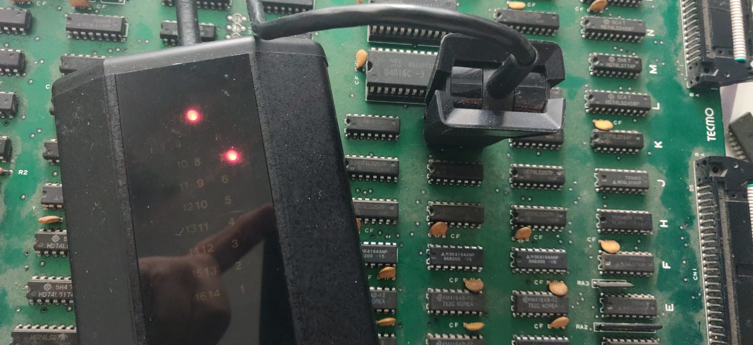
Red light indicated a bad output – I pulled the suspect:
Confirmed bad out of circuit:
Replacing this chip fixes the jerkiness. Game is perfectly playable. Sound and controls tested OK.
Summary :
- 11 DRAMs (SAMSUNG),
- 2 EPROMs,
- 1 74LS193 (TEXAS INSTRUMENTS)
Some months after this repair, I found the proper original Silkworm schematics, scanned it and upload to my GitHub here:
https://github.com/DocteurPCB/schematics/blob/main/Silkworm%20%5Bschematics%5D.pdf