Atari 800xl repair log #2

 Computer Repair Logs, General, Repair Logs  Comments Off on Atari 800xl repair log #2
Jun 022018
 

Although I grew up with a Commodore 64, I have a soft spot for Atari 8 bit machines. My mission in life is to save them all from going into landfill.

I spotted this grimy Atari 800XL on Gumtree very recently as untested, it came with an Atariwriter Word Processor Cartridge. I met the friendly chap selling the item and we did the exchange for the computer at Town Hall steps, which is a popular meeting place in Sydney.

Taking the machine apart, I was happy to see that the machine was fully socketed and that the PCB was in excellent condition despite it needing a good clean. Actually, I was expecting a fully socketed machine because it was made in Hong Kong just like my 600xl was. Another pleasant surprise was the brand of DRAMs used ( OKI ) instead of the mT variety, which have a bad reputation for reliability and were used extensively in the Atari 8 bit and C64 line.

I had a close friend of mine over after work and we went through the troubleshooting together. Unfortunately, not much happens after power it up. A black screen most of the time and sometimes an intermittent picture, obviously this is a sync issue.

Sometimes I manage to get a screen that looks like this. This is a good sign. At least I know the CPU, ROMs and DRAMs are working to some extent to produce this screen.


Luckily I  have a fully socketed 65XE to swap parts to and from.  I also tried a known semi good GTIA which was bad on one output only but produced a nice clean picture in a working machine. The GTIA is responsible for generating the luminance, color and csync signals to produce an image to the screen.

Replacing it doesn’t change a single thing so I consult the schematics, the signals go directly to a hex non inverting buffer ( 4050 ) so I switch my logic probe to the CMOS setting and start probing the chip. Output 6 ( lum0 ) is good, lum1, 2 and 3 were all bad and all outputs were floating. I wanted to check the CYSNC line (  composite sync ) and that was also floating ( no signal at all  ).

I short the input and output pins of the 4050 ( pins 14 & 15 ) with my logic probe briefly which restores the picture to the screen.

Replacing the chip completes the job!

Now onto the next challenge, cleaning the motherboard and case!

Jan 262017
 

This is part two of my C64 repair which documents the replacement of the bad character generator rom using a standard 27c64 EPROM. My local electronics hobby store did not have anything else on hand; I was hoping for a 27c32 because that’s what most folks on the internet seem to be using to get this repair done. I didn’t want to wait, so I settled on the 27c64.

The first step was downloading a c64 character rom ( 901225-01 ) with a checksum of $F7F8 from the internet. There are plenty of sources for these.

After downloading the 4kb binary I ran the following command under Windows to fill up the entire 8kb of address space of the 27c64 ( upper and lower 4kb have the same data ). I couldn’t quite remember which half I needed to burn the contents to so this was a quick and fail safe solution.

copy /b 901225-01.bin+901225-01.bin 901225-01-doubled.bin

I take the 8kb binary ( 901225-01-doubled.bin ) and burn the image to my 27c64 EPROM.


I bend the following pins outward on the 27c64 and cover the window with a sticker once the data is written.

1,2,20,23,27 & 28 ( bent out ).

I made an adapter using a machined pin socket. This is the diagram I used to re-wire the chip which I found on this German site.

https://forum.classic-computing.de/index.php?page=Thread&threadID=4694


2532 pin 18 -> 27c64 pin 23 ( A11 )

2532 pin 21 -> is not connected ( VPP )

27c64 pin 20 -> 27c64 pin 22 ( /CE & /OE tied )

27c64 pin 1,2,26,27 & 28 ( VPP,A12,NC,/PGM & VCC all tied ).

Once I finished wiring it was time to double check my work. I then select a 2532 device on Max Loader, load the original downloaded character generator rom into the buffer; this has a checksum of F7F8 which will be used for verification purposes.

With the wiring complete I’m now ready to verify it’s contents. I will read the device as a 2532 EPROM and if all goes well it should report a checksum of F7F8

With the re-worked EPROM inserted into the ChipMax I hit verify. F7F8 was what I was after.

With that result I was so confident it was going to work that I trimmed the protruding pins and inserted the device into the C64 to produce the results I expected.

Dec 182016
 

This c64 gave me the following screen on power-up. Flickering characters with artifacts and a vertical line through the middle of each character. After going through the symptoms on Ray Carlsen’s site, I thought this may be bad colour ram. Swapping out the 2114 didn’t make any difference and colours associated with the characters looked good anyway, so I don’t know what I was thinking there.

After thinking about this for awhile & looking at the pattern closely, I had an idea that this may be a bad character generator ROM at U5. To prove this theory, I could type in a short basic program to copy the entire character set from the ROM into RAM, then tell the VIC 2 chip to use the character set in ram and reprogram one of the characters to one of my choice. The Commodore 64 has great features such as programmable characters which is very useful for games.

Luckily I don’t have to think too much as there’s already an example at the link below.  So I begin typing some basic commands. The problem is my typing has to be super accurate because I can’t see what I’m doing and any typo will screw the troubleshooting up. It took me 3 or 4 goes before I finally got it right.

https://www.devili.iki.fi/Computers/Commodore/C64/Programmers_Reference/Chapter_3/page_109.html

After typing in “POKE 53272,(PEEK(53272)AND240)+1” as shown above, the flickering stopped although the artifacts obscuring the characters were still there, which was to be expected because we’ve just copied corrupt data. The computer was now getting the character set from RAM instead of from ROM. Now to change the letter T to a smilie face. I enter the following program and run it.

10 FOR I=12448 TO 12455: READ A:POKE I,A:NEXT
20 DATA 60, 66, 165, 129, 165, 153, 66, 60

Pressing a T shows a smilie face which looks complete without artifacts or a line through the middle of it. So I know that the VIC 2 chip is OK.

I remove the old mask rom and install a socket. My EPROM programmer is currently out of action so I don’t have the ability to verify the character rom or program another EPROM in its place.

But for now I can extract a known working EPROM from my own C64 into this one for troubleshooting purposes . After powering up, the character set shows up perfectly. Now all I have to do is program another EPROM when I get around to it and this c64 can go back to its owner.

Dec 102016
 

This Atari 800xl has definitely seen much better days. A work colleague picked this 800xl off eBay plus a battle worn 65xe and some power supplies and other junk. Initially we had some issues troubleshooting but the symptoms were typical of a faulty power supply and bad DRAMs after re-testing with a reliable power source.

image

One of the power supplies had the Atari logo with a foreign AC plug. These are absolutely useless to me because they’re sealed with epoxy and could not be repaired. The other two types were also sealed with epoxy, the connectors with the 7 pin din plug would later be salvaged for an alternative source of +5v DC using a basic switching adapter for usb hubs / routers. I read that they fail spectacularly when they do with over voltage. DRAMs don’t like voltages far above the normal voltage levels and will fail very quickly. I’ve also read that the sealed epoxy types are very reliable and when they fail, they supply low voltages due to bad caps which aren’t harmful to the Atari. Regardless of what the truth actually is, these power supplies are well used and it’s likely that they’ve already failed or due. The other common cause of a dead Atari is a “Commodore 64 attack”,  the c64 has the same 7 pin din power supply connector and was often intentionally or accidentally plugged into the back of an Atari causing instant death to DRAMs & anything CMOS. The Atari only accepts +5vdc, Commodore decided to use 9vac in addition to the +5vdc.

The XL and XE series have a really neat diagnostic tool built into the OS ROM. When the option key is held in during power up, it triggers the software to boot into the diagnostic mode however, when bad ram is detected it automatically boots into the memory test as shown.

image


The red squares indicates that the ram test has failed. Normally, 48 green squares should be present but unfortunately most of those are red. Each square represents 1kb; would that mean it only have 48kb of ram? Well not really. The 800XL has 64kb of ram but the built in diagnostics only tests 48kb of that. It’s a very simple test. The higher chunk of 16kb of RAM isn’t tested, I guess because this area of memory lies underneath the Atari  OS ROM. Then there’s also the first couple of pages of RAM which are used to store some variables.

Each DRAM represents 65535 words x 1 bit, so you need 8 of these to make up 1 byte of ram per address. Some of the later models use 2 x 4464 DRAMs in the XE series.

Unfortunately this is a revision D motherboard which means only half the chips are socketed ( cost savings ). So we need to remove our DRAMs and test them outside of the circuit.

image

I could also troubleshoot by piggy backing to identify a bad chip but that won’t work if a chip is shorted. The board has previously been worked on and a new DRAM was already installed, this replacement could have occurred years ago. We have at least 1 additional dram fail and we don’t know the history of the machine and when this failure took place. It would be wise to replace the entire 8 devices as it’s very likely we will see another DRAM fail. Besides, this brand of DRAMs are known to be unreliable even when they were new and they were also used in the C64. It’s also very less likely that we have one or both of the 2 74LS258 DRAM address muxes fail.

So I remove each DRAM one at a time, install an IC socket and test them out of circuit with my trusty Micromaster LV48 EPROM device programmer. I tested the previously replaced DRAM and it passed the test however I only found 1 bad DRAM and it was the first one at U9 ( clearly marked X with my screwdriver ) so I don’t mix it up with the remaining working devices.

image

I don’t have any spare 64×1 DRAMs on hand. But I do have some in a ram expansion board which was installed to expand the 600xl’s internal memory from 16kb to 64kb. I finally convince myself to salvage the DRAMs to fix the 800xl since I already have some spare TI 64x4s which I can put in my 600xl and use it to troubleshoot the dead 65e, it would require a modification but it’s a very simple mod which many have done. Besides the ram board is totally unnecessary as pointed out by people on Atariage who made jokes about it as I tried to identify its origin.  I was also expecting to receive my Antonia 4Mb upgrade board from Poland to install in the 600xl so I wasn’t really needing the 64×1 DRAMs anyway.

The disgraced ram board.

image

Installing sockets and replacing the entire stack of DRAMs seems to have cleared the ram error but I intend to load up several games that use up the entire 64kb to make sure and test the machine over a few hours. I also tested each DRAM in my device programmer to verify them before installing them in the 800xl.

image

Whilst I’m working on this I’m also giving the Atari 800xl case some whitening treatment using a simple solution of laundry booster and water. I submerged the parts in this milky solution and left it in the sun for several hours over the weekend. This is a very effective and cheap alternative to some of the other solutions out there. The sticker had come off, so I had no problems submerging the bottom half of the case. I would later glue the sticker back on once the case was dried.

image

I like the results. Some keys are still slightly yellowed but I don’t mind.

image


A few hours go by playing my favourite game on the Atari, Dropzone. Now I have a bunch of 4164 DRAMs which I’ll use for troubleshooting purposes.

image

RAM test shows no problems but I had an issue with the TEAC television set shown previously and l had to replace it with this piece of junk. That’s two sets gone in two months with no desire to repair them.

image

With that done. It was time to give the machine back to it’s owner and start working on the 600xl which I’ll use to troubleshoot the 65xe ( I’ll cover that in my next post ) by substituting in parts until the 600xl breaks.

These are the instructions I followed and results.  3 wires, bend up some pins ,some soldering and you’re done. I had to reinstall the 2 x 74LS138, 74LS375 from the RAM board to the machine. There was also a 74LS32 missing which isn’t really needed depending on the variation of the mod you’re performing but I managed to scrounge one from an arcade parts board.

https://www.mathyvannisselroy.nl/xl600k64.htm


600xlupgrade

2 x TMS4464 DRAMs installed. Much better than the expansion board!

Sep 112016
 

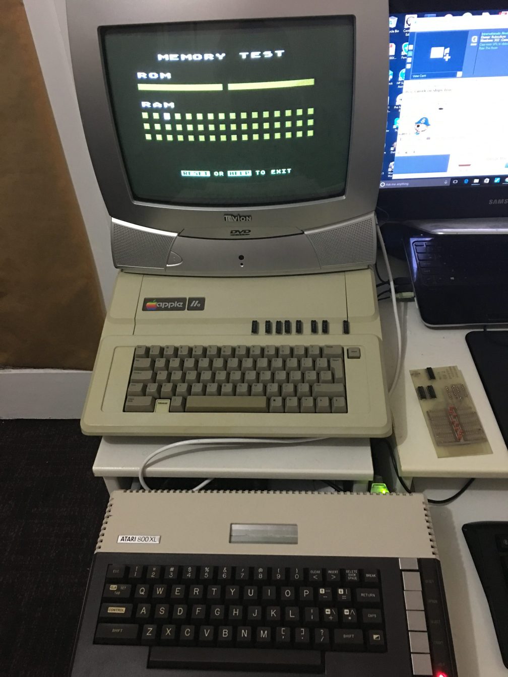
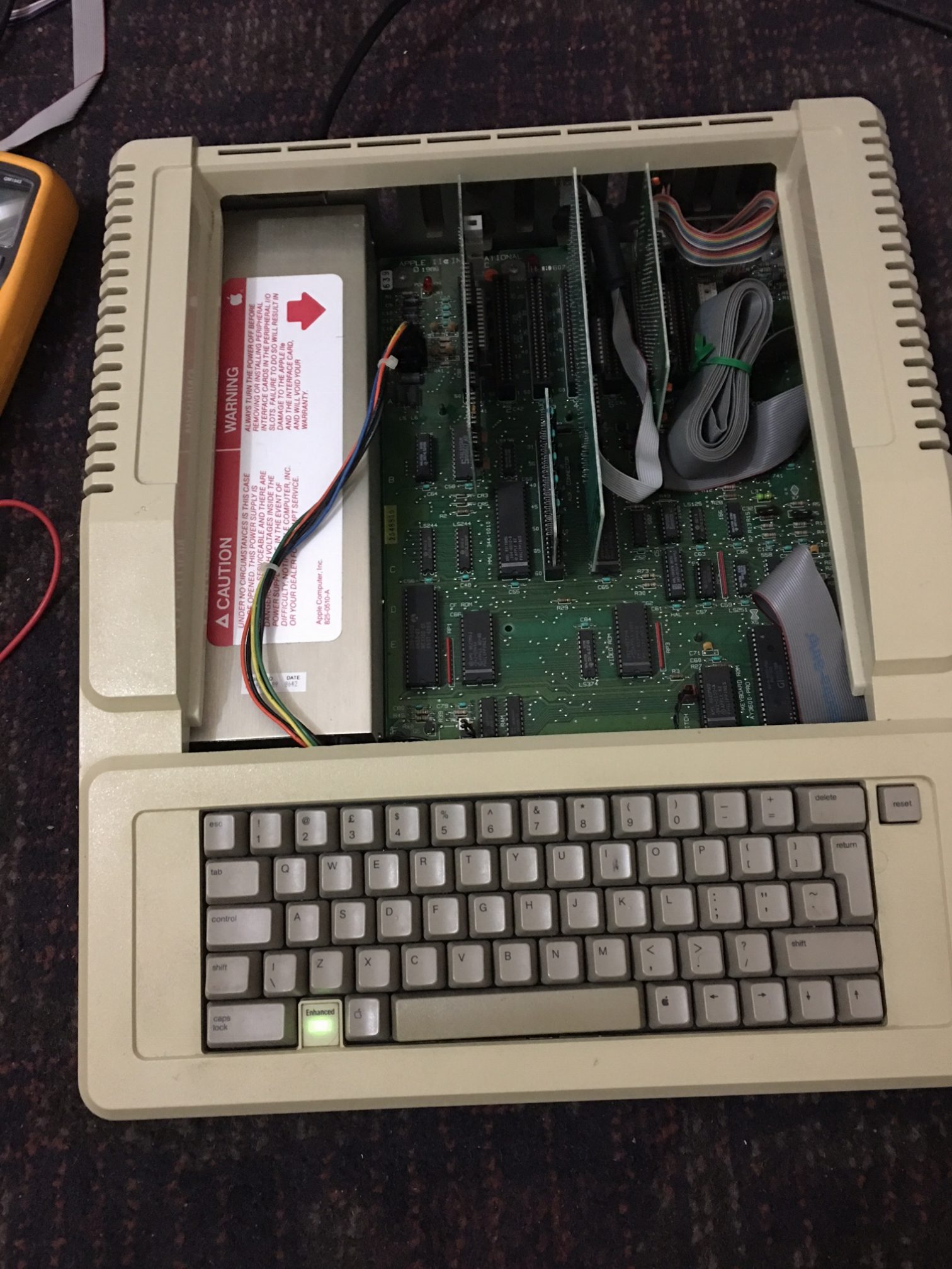
I recently picked up an Apple //e enhanced computer to repair and to relive some memories. Due to the machine’s age ( especially because of the power supply )  I was mindful not to power up the machine and risk damage to the logic board.

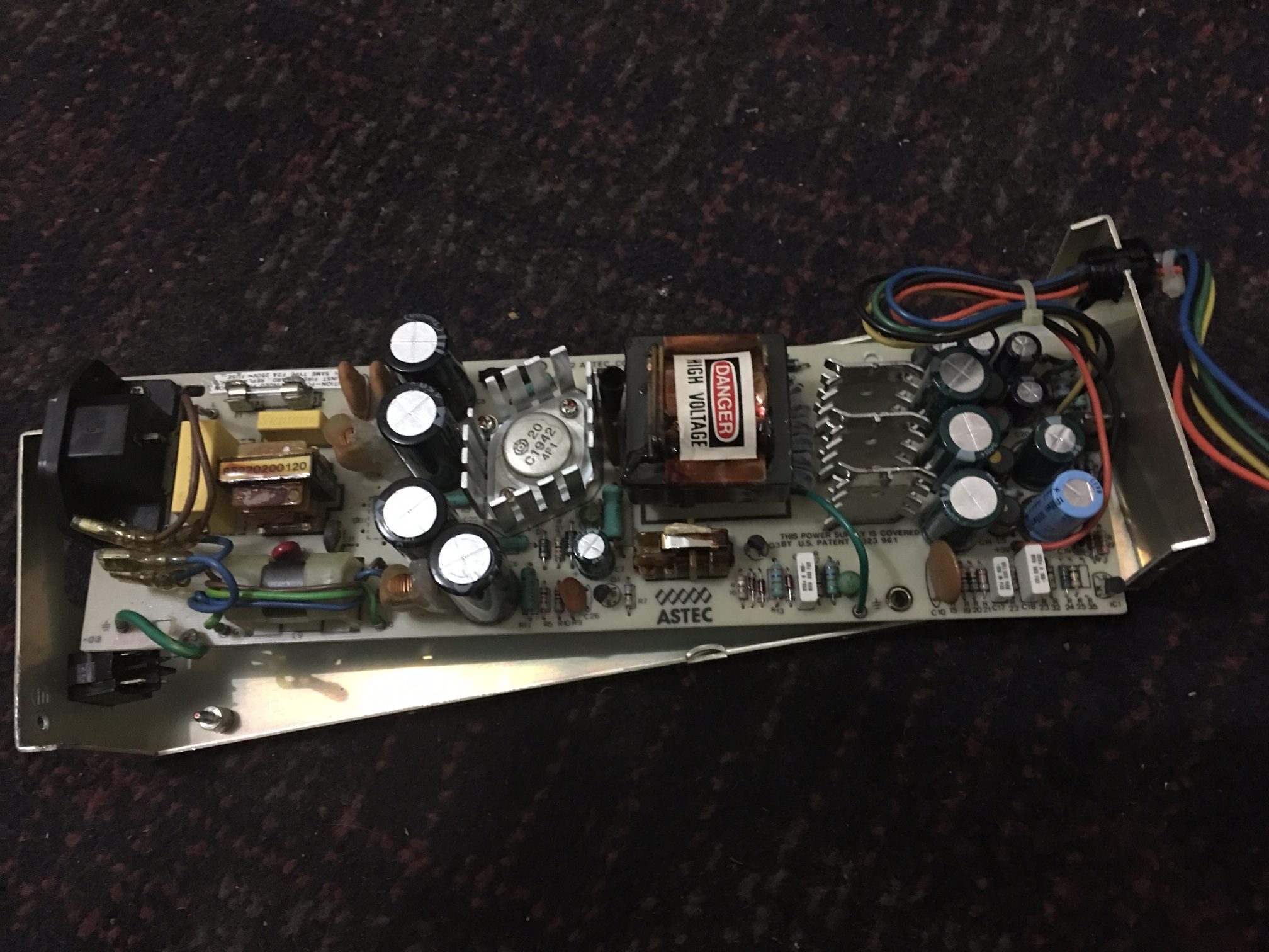
I disassembled the power supply and wasn’t at all surprised at what I saw based on what I’ve read, there was no way I was powering this thing on and taking any chances although this was a very high quality power supply compared to power supplies of the same era. This is an astec AA11042C, this version is rated 240v and there were actually two different types available in the Apple ii line. I checked the fuse which looked fine and tested OK with my DMM.

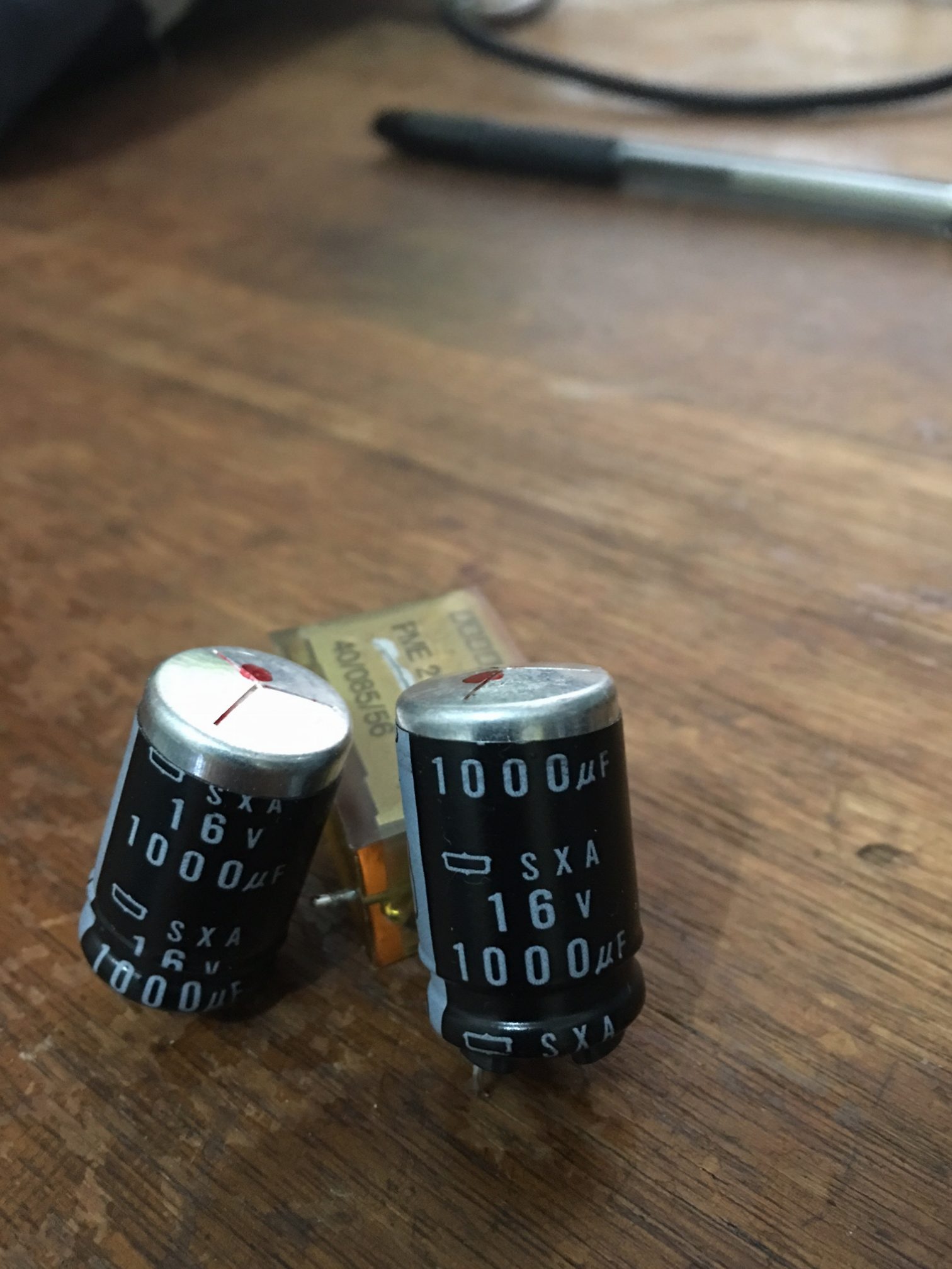
I then removed all electrolytic capacitors and recapped the entire board including the two Rifa filter caps which can fail spectacularly and spill brown coloured goo everywhere. Some capacitors revealed scorch marks on the PCB after removal. The 47uf 250v capacitors from the high voltage side looked fine but were way off spec.

2 bad electrolytic capacitors pulled from the low voltage/output side

image13


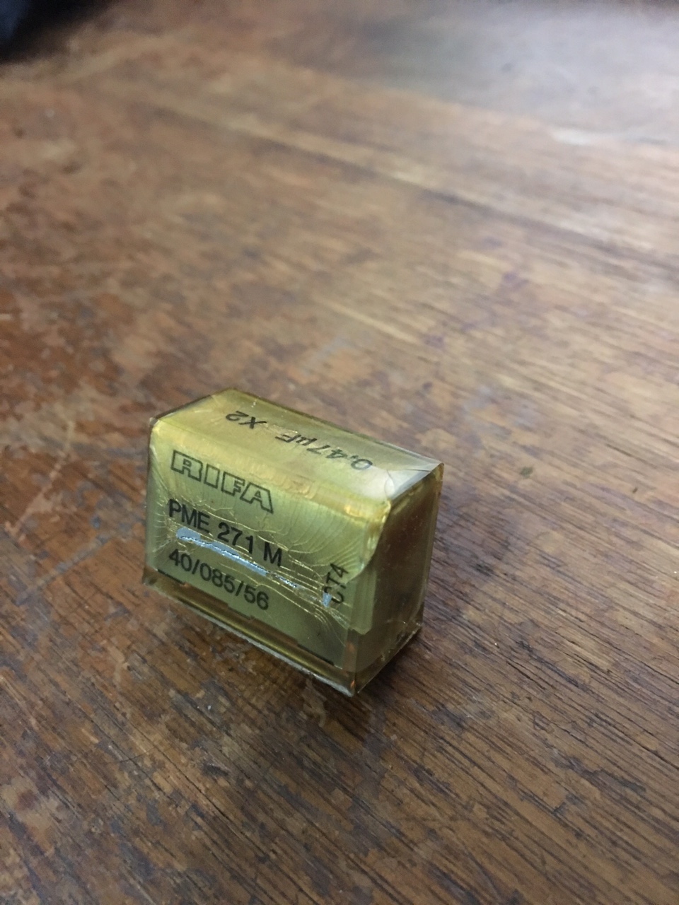
A Rifa filter cap. ( Note the cracks! )

Apparently moisture gets inside the cracks and the cap explodes. Not taking any chances, it has to go.

image12

Astec rebuilt with brand new electrolytics & filter caps.

I ended up installing two filter caps made by Suntan, this brand doesn’t have the best reputation in the world but I can swap those for higher quality caps once I get the unit functioning. These were all I could find ( the yellow rectangular looking things near the inductor) and I was so desperate.


image4

I tested the power supply but quickly found out that like all switching supplies, nothing will happen without a proper load or with a short. With the power supply connected to the Apple, nothing happened which was good in a way because I didn’t see any smoke. If I were taking my chances in the same way with an Atari or Commodore power supply then things might have turned out a little different 🙂

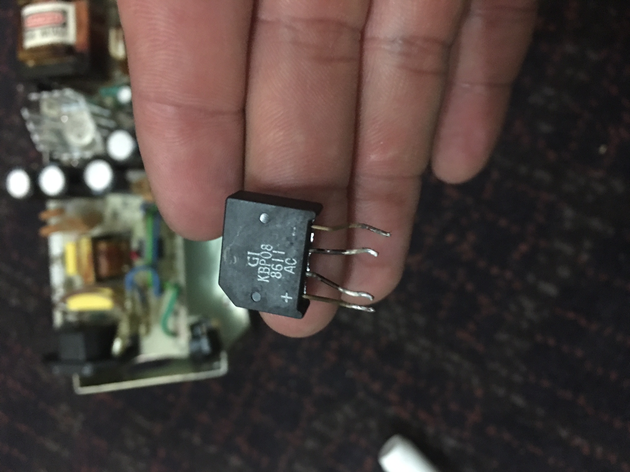
There were no voltages present on the logic board of the Apple //e. This prompted me to look deeper. The bridge rectifier ( @ DB1 ) looked a little cooked or oxidized even though it tested good with my DMM, the issue wasn’t there but I replaced it anyway.

Scorched or oxidized bridge rectifier ?

image5

I then started reading a comprehensive troubleshooting guide in the following PDF document.

https://www.applefritter.com/files/Apple2e_Repair_SAMS1985.pdf

I ended up removing a bunch of small transistors, the large power transistor,diodes and re-installed them after they checked out fine. I replaced the SCR ( silicon controlled rectifier ) at scr1 as I have no means to test it. The scr1 shutdown transistor at Q4 tested good. This area is also known as the crowbar circuit which disables the power supply if there’s an over-voltage or a surge, this protects any downstream components like the sensitive stuff in your computer from damage.

I was stumped at this point as none of the above actions solved my problem.

I took another closer look at the PCB and found this burn mark circled in yellow. I removed the 2w resistor which still measured 27 ohms out of the circuit. I re-installed it as it was good.

image15

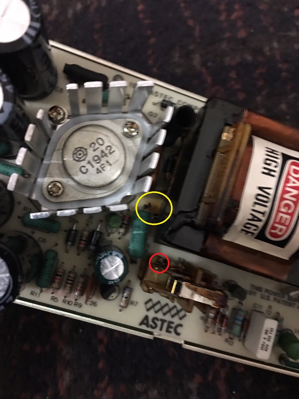
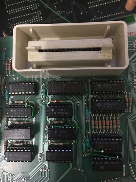
The above link to the document also mentions to check the windings on transformer T2 and T3 ( PWM control isolator )  for continuity. I remove the smaller transformer ( pictured above, adjacent to the astec silkscreen logo on the pcb ) thinking that I’m wasting my time with this but check for continuity anyway.

There are 6 pins on the bottom of the T3 which are soldered to the PCB. There appears to be 3 separate sets of windings but 1 set of windings had no continuity between two of its associated pins. I found a small break in the winding at the bottom of the transformer ( circled in red ) and soldered it to its corresponding pin. If the break was anywhere else then there would be no way of repairing it, I just got lucky I guess.

I re-assemble the power supply and apply power to the computer and presto. The internal speaker beeps at me and the kb power led illuminates. Failures within transformers are relatively rare but I have just proven to myself that its more likely to happen than I originally thought.

image1


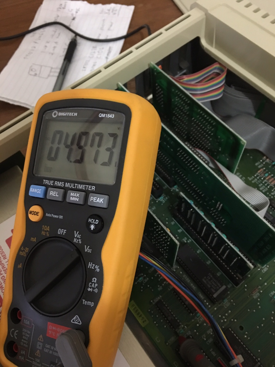
Taking some measurements ( -12v, -5v, 5v & 12v ).

4.97 volts DC, looks good to me!

image2

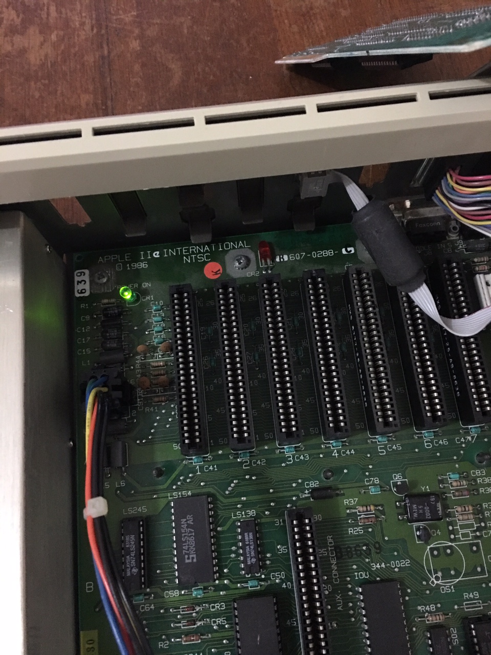
The red led on the logic board is busted, so I replace it with the only one I have on hand and it’s green.

image7


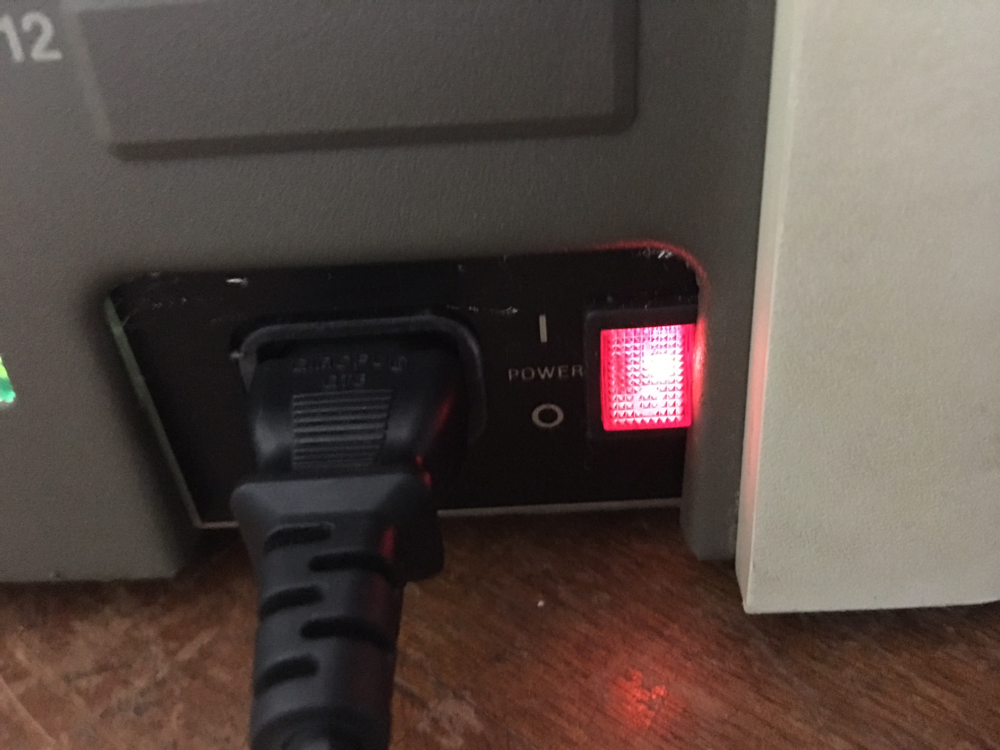
I also accidentally broke off one of the terminals on the a/c switch due to too much tinkering so I replaced it with one that illuminates. I like it better than the old one.

image8

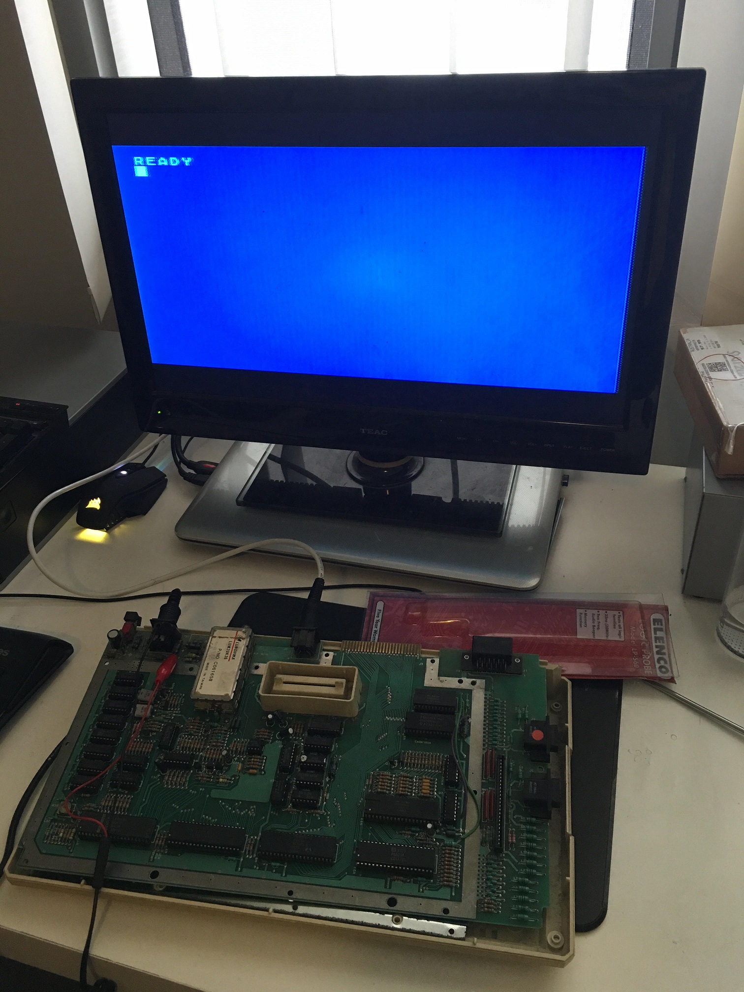
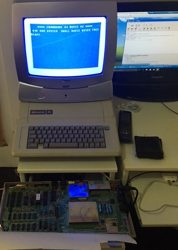
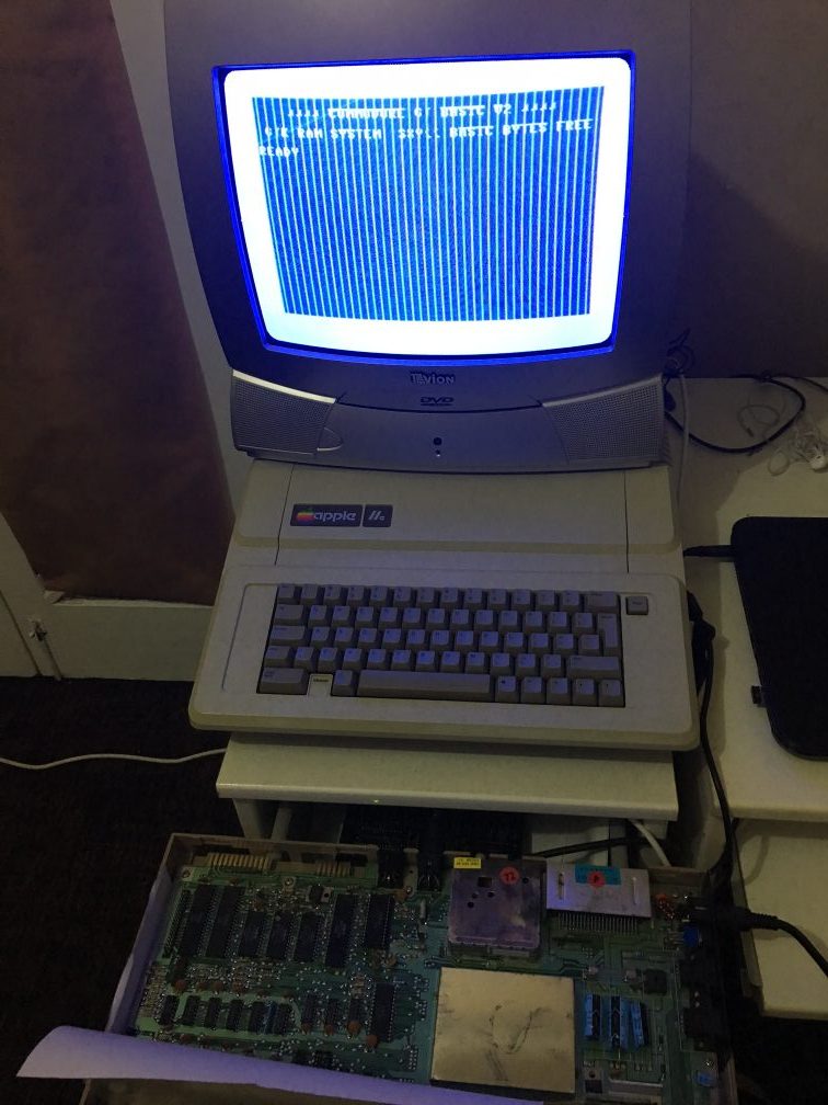
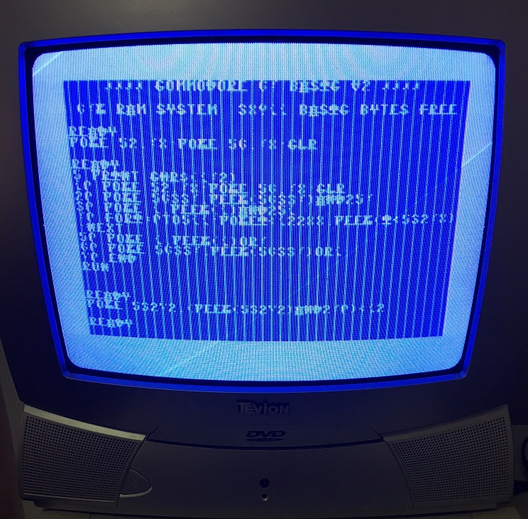
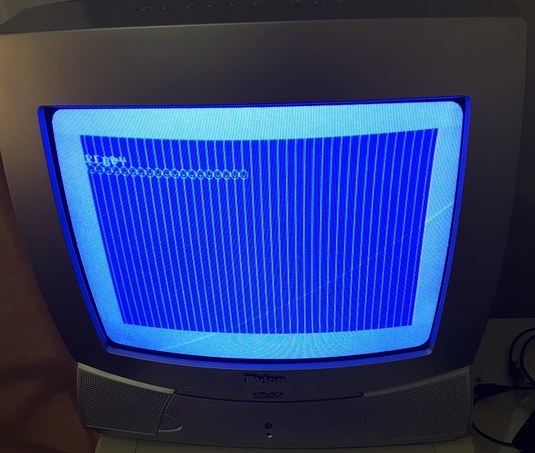
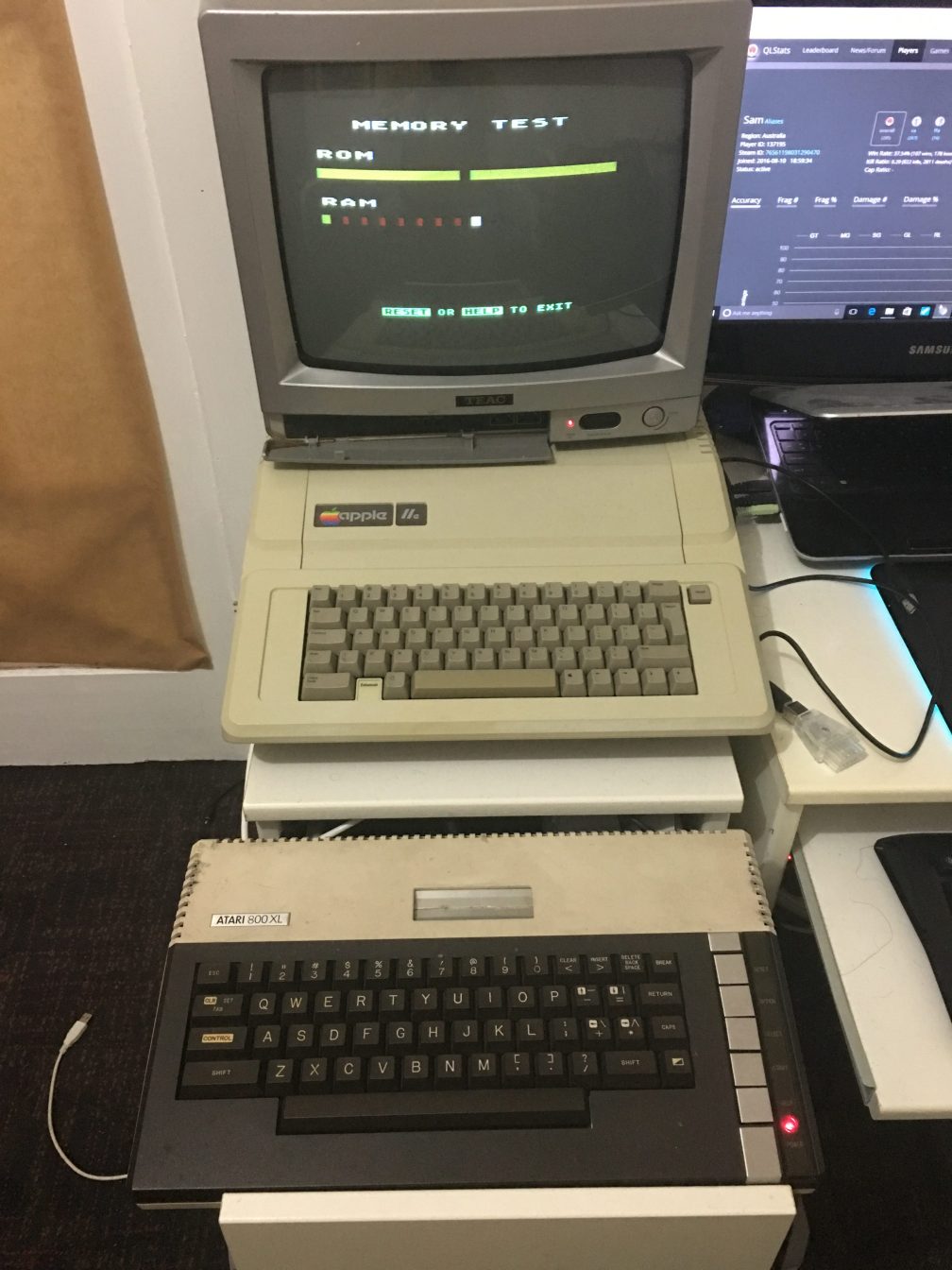
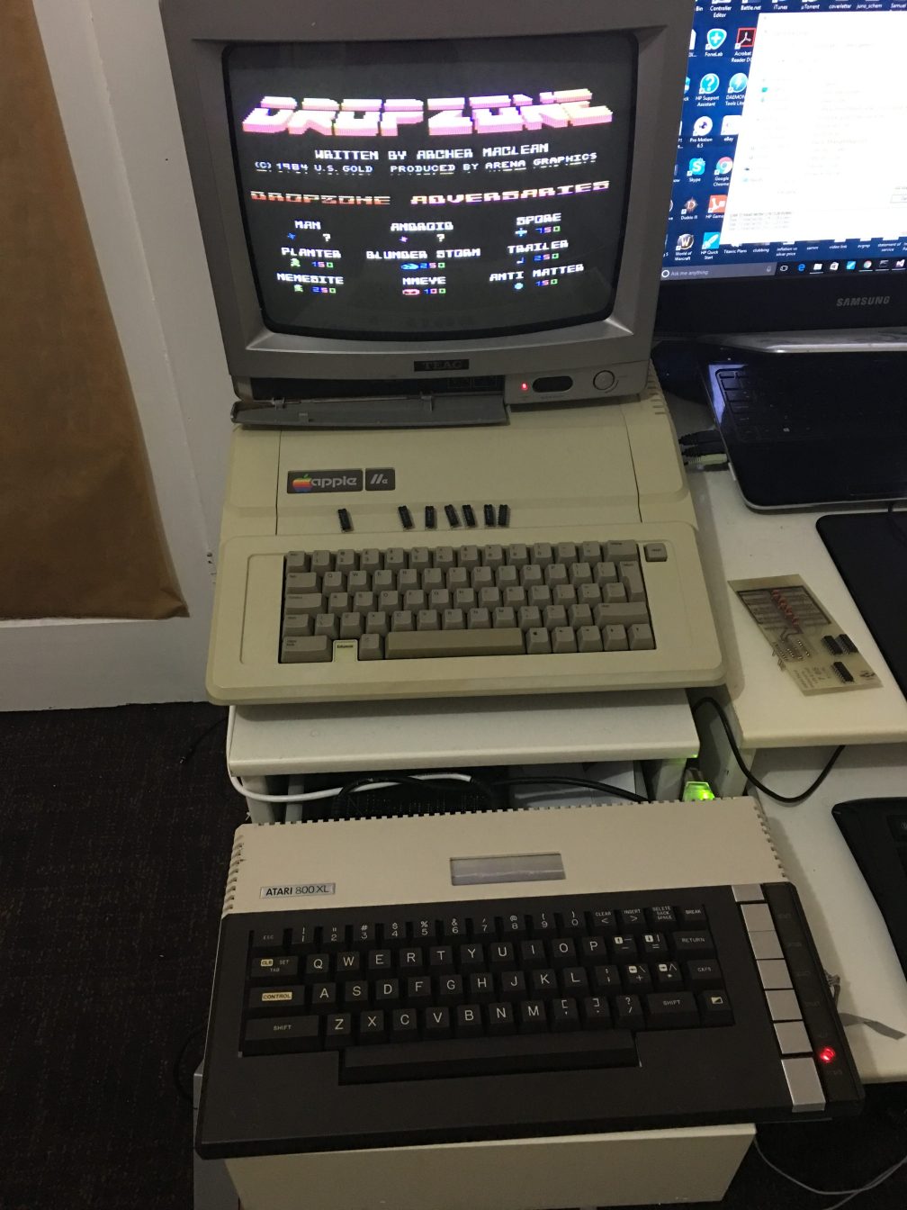
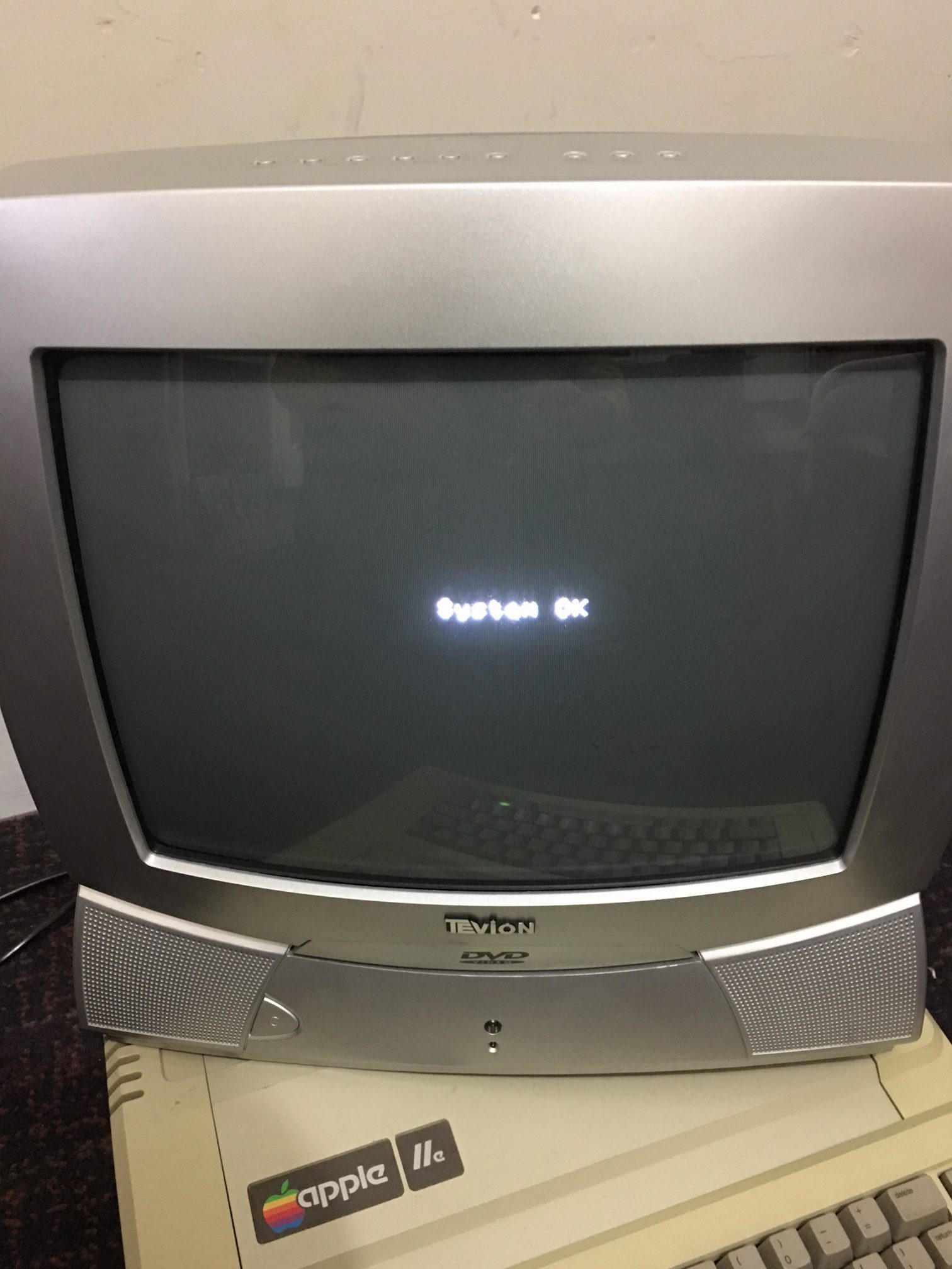
A backup CRT TV hooked up.

image11


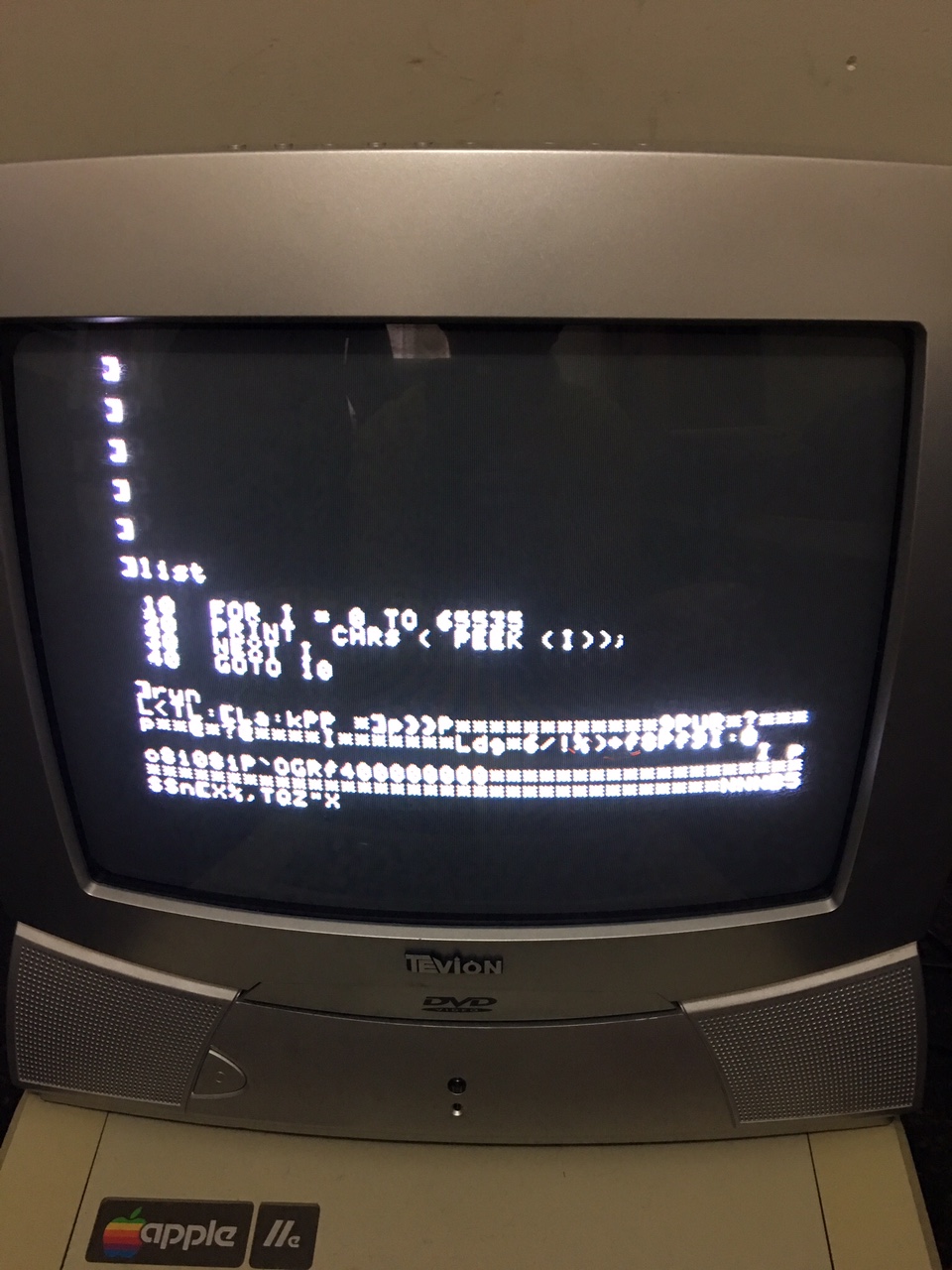
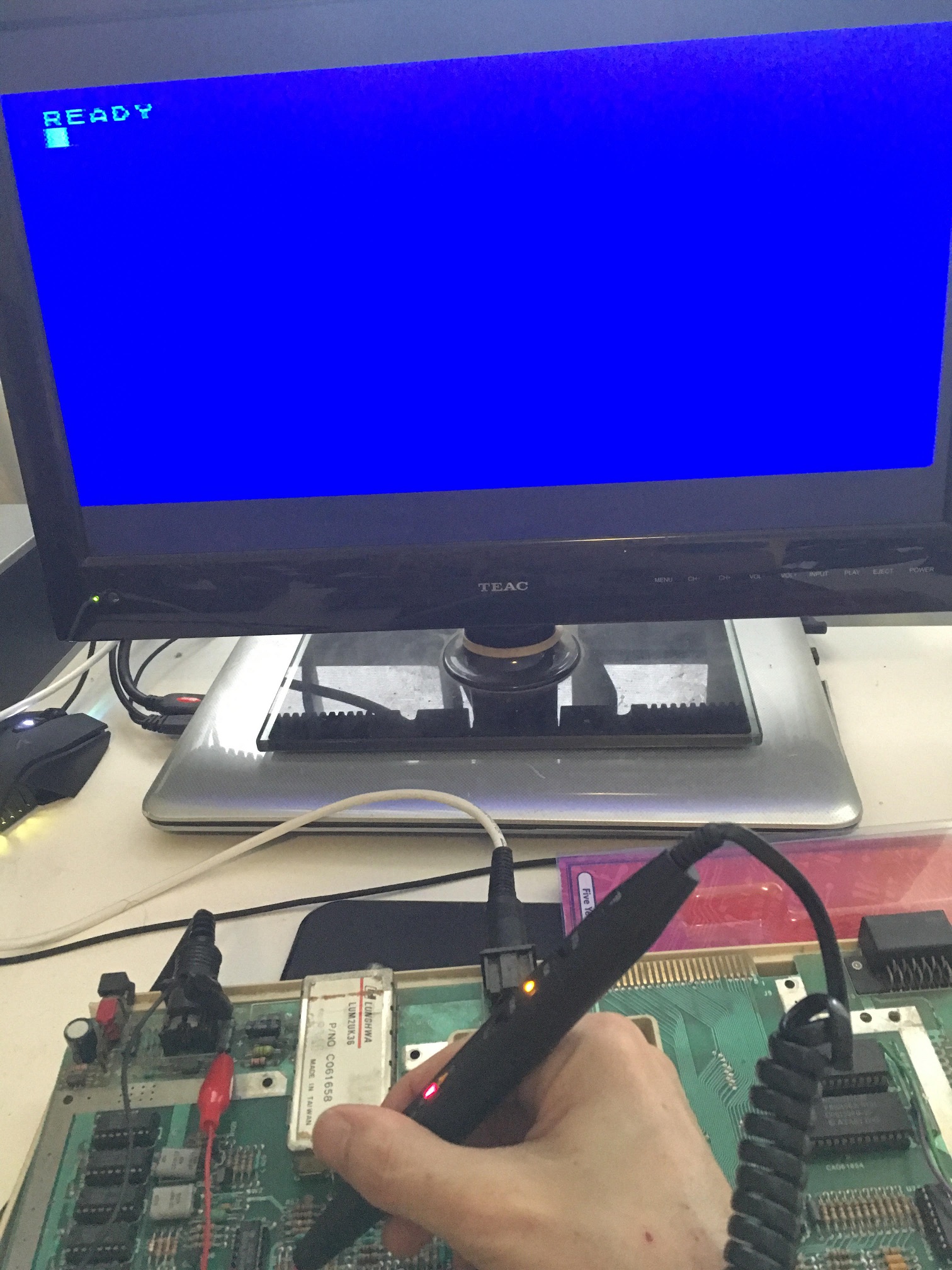
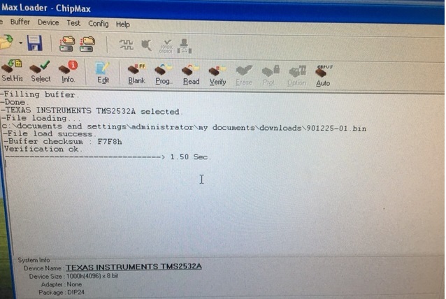
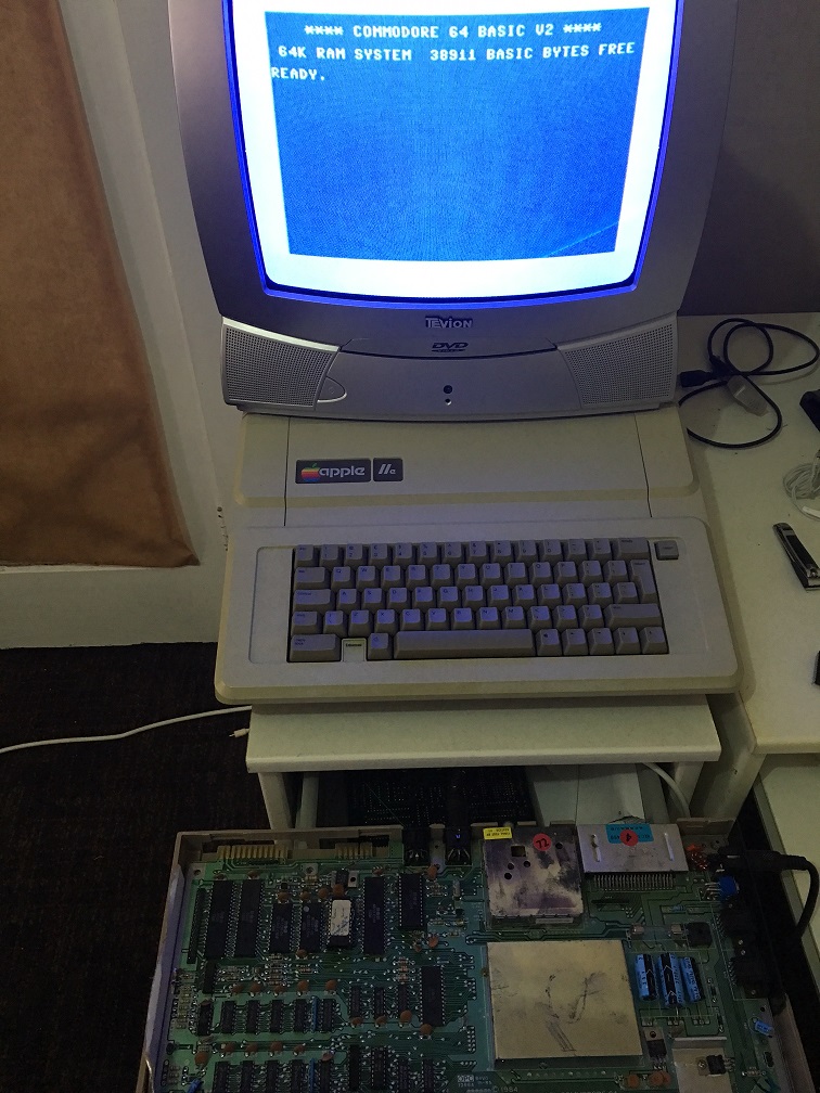
Passes self diagnostic tests

system-ok

That’s pretty much the end of this repair. I do have some issues with the keyboard which are fairly trivial and I’ll address that later when time permits.


References:

1. Apple 2e 6502 Computer Repair Information – SAMS COMPUTERFACTS

https://www.applefritter.com/files/Apple2e_Repair_SAMS1985.pdf