Oct 142018
 

Some time ago I bought an untested Sega Dreamcast console (with no video cable or other accessories included) with the intention someday to replace the optical drive with a GDEMU :

I was lucky because it was a japanese HKT-3000 model with VA1 motherboard and 3.3V GD-ROM assembly so perfectly compatible with Deunan’s GDEMU :


Some days ago I finally got an A/V cable so it was time to power up the console for the first time.With my disappoint all I got was a disturbed video signal, nothing came up on the screen:

I opened the console and did an inspection :

First of all I looked at PSU and immediately my attention was caught by the big 100uF 200V electrolytic capacitor @C3 which was clearly ‘bulging’ (you can see how top of the metal can is dilated)

This capacitor has a very important function as it filters (suppressing the ripple) the AC source that then get transformed by the rest of the PSU circuit.It measured little more than 7000 pF (0,007 µF) when tested out-of-circuit showing no ESR value at all :

I replaced it with a low-ESR one and checked in circuit the ESR of the other electrolytic capacitors, they were all good:

I powered up the console and I was delighted by the startup intro animation (sorry for B/W picture but my Philips CM8833-II monitor doesn’t accept NTSC signals)

Now waiting for a joypad and then time to play with wonderful Deunan’s GDEMU ODE!

 Posted by at 10:08 am

Nintendo Entertainment System (NES) repair log

 Console Repair Logs, Repair Logs  Comments Off on Nintendo Entertainment System (NES) repair log
Aug 282016
 

Maybe this isn’t the typical repair log but it has a couple of pictures here showing what can happen.
I was actually given this by a reader of the site and he wanted to donate something by way of thanks. He told me it had some issues playing the cartridges and suspected the ZIF connector that the NES is infamous for.
As you can see its boxed and in really nice condition.
nex_box
nes

I powered up the console testing the games that came with it.
nex_fault1
cad_fault
smb3_fault
smb_fault

You can see jailbars on most of the pictures. Occasionally the game didn’t boot at all and when they did the sound was a low static noise.

Id already ordered a new connector in anticipation.
nes_connector

I did originally attempt to bend the pins on the original connector back but it made no difference and a couple looked too far gone so it went in the bin.
There are countless guides online for taking apart the NES and replacing the connector so I wont really go into it on here.

There goes the warranty!
nex_warranty

With the connector fitted I now get this. Its currently playing through RF so excuse the poor picture.
smb3_fix

I never really had a NES before so being able to play Mario 3 is going to be a treat.
Thank you very much to Kieron for this wonderful donation.

 Posted by at 11:36 am

Sharp SF-1 (SNES TV) repair log #2

 Console Repair Logs, Repair Logs  Comments Off on Sharp SF-1 (SNES TV) repair log #2
May 222016
 

The 14″ TV is up now.
This one was a lot more involved.
Before starting on this one I had tested the previous PCB with this TV so I knew for sure the TV part was operating fully.
sf1-repair

When powering this up I got no audio or video, just a black screen. Using the external A/V output also gave me nothing.
I couldn’t find anything obvious visually on the PCB itself.
Ive read a lot in the past about SNES repairs and the CPU’s seem to be a weak point. I started prodding around the CPU with the scope and even though all the voltages and clocks looked good I could see any activity.
I had a known working spare SNES which I opted to sacrifice for parts.
sf1-pcbmark

I replaced the CPU and once again checked for signals. This time I had life but it gave up after a few seconds and still didn’t give me any output. This cycle was repeatable on resetting the machine.

I next opted to replace the ‘S-WRAM’ (work RAM) positioned next to the CPU.
Replacing this gave me audio but no video so at least I knew the game was running which was great to hear.
At this point I tried the external A/V connector again and got a good picture.

Probing the ‘S-Enc’ chip yielded no outputs at all despite all inputs being as expected. I replaced this and everything came up good. Time to reassemble and reclaim some bench space.
Thats both of these rare units fixed up.

sf1-pair

 Posted by at 10:21 am
May 212016
 

A couple of friends were looking to get their SF-1 SNES TV’s repaired. Not one for letting such gems go to ruin I offered to try and help out.
There were two units in need of repair, a 14″ and a 21″.
sf1-top

This log will focus on the 21″ version first.

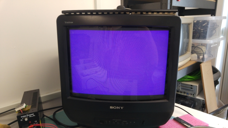
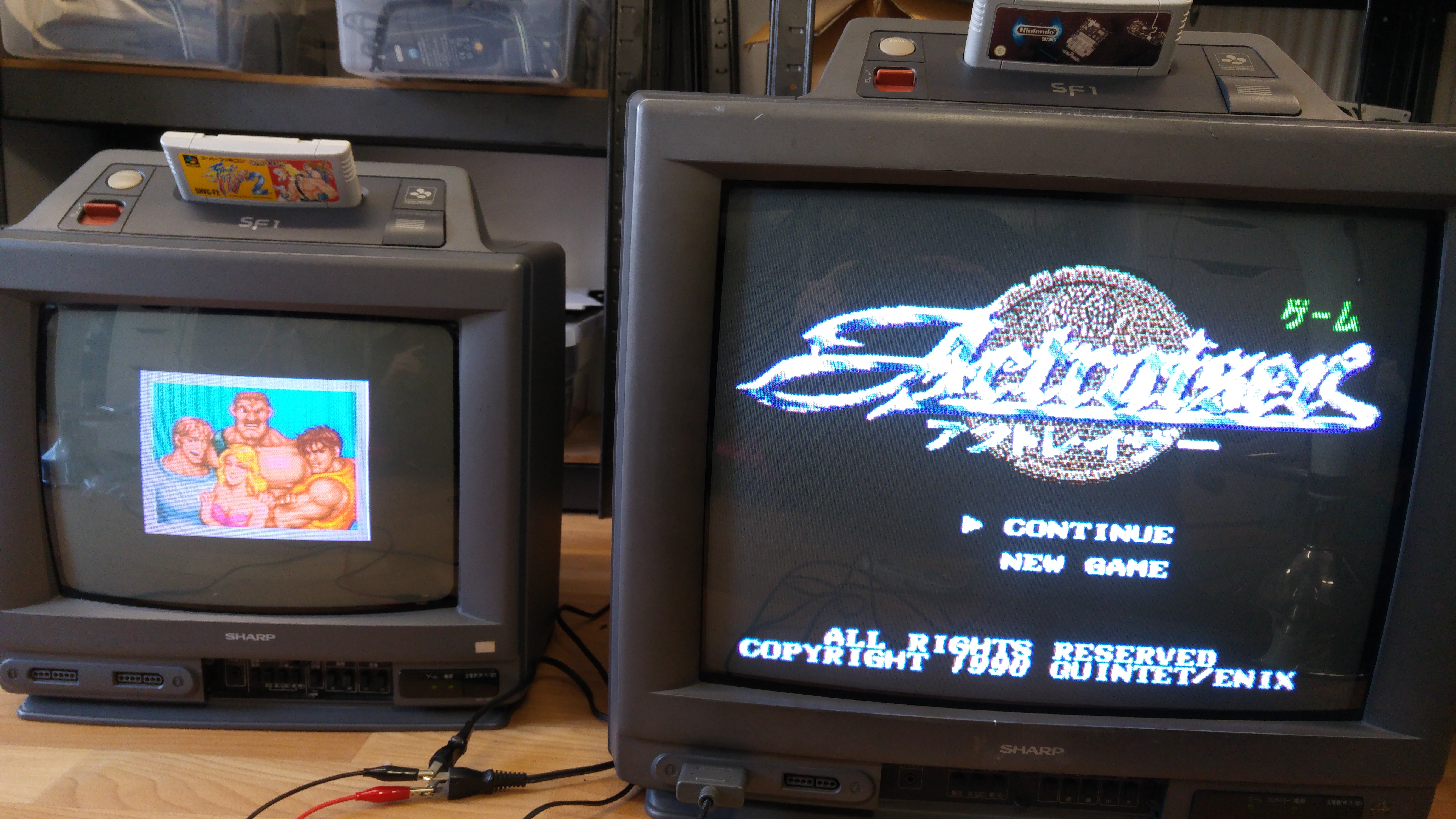
On power up with a game fitted I got audio and a very faint greyed out picture.
I had been given an RGB scart cable with these so as they have the standard A/V output port on them I thought I’d give that a go.
I got this
sf1-sync

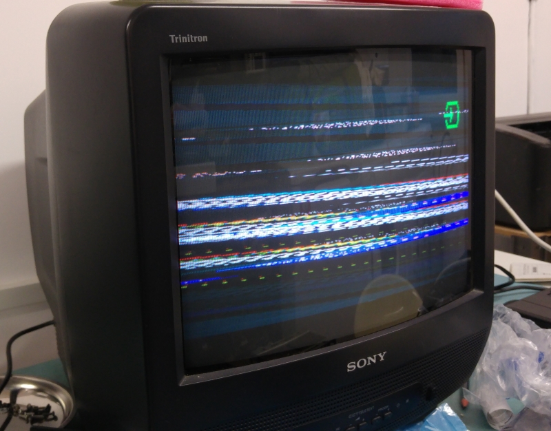
As you can see the sync signal is off but I could see a nice colour picture. This gave me initial hope that the PPU’s were not to blame for the grey faint picture.
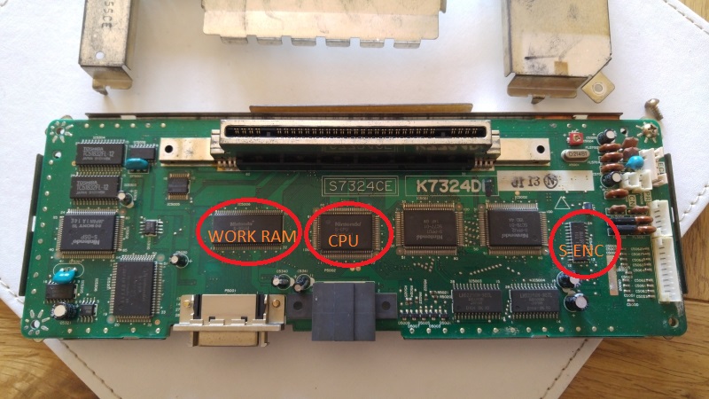
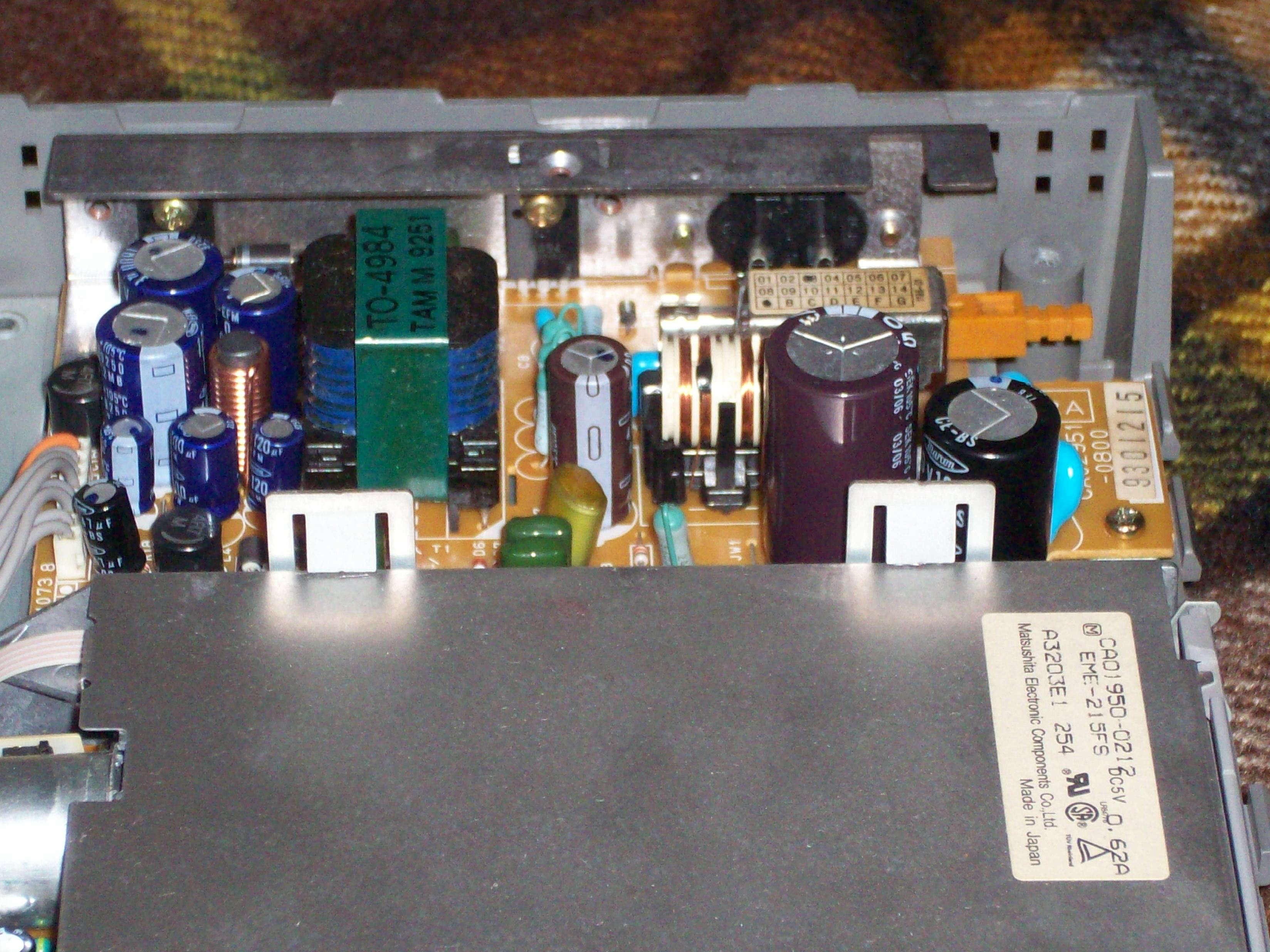
Taking this unit apart was a bit of a pain with the SNES part being sandwiched in at the top but I got it out and looked for anything obvious.
sf1-pcb

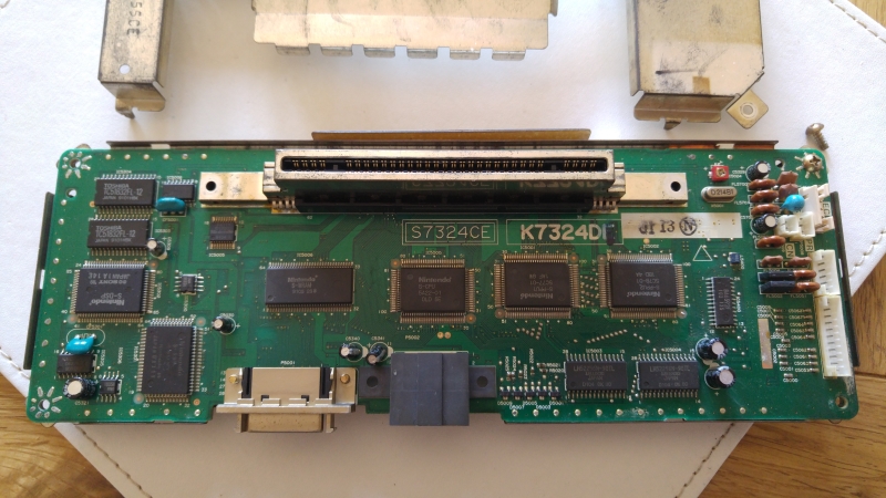
(Note that this PCB image is actually from the 14″ version. The 21″ version has a very similar PCB with only the connector location being located differently. I forgot to take a picture of that one.)

There was nothing obvious so start looking at the missing sync signal first.
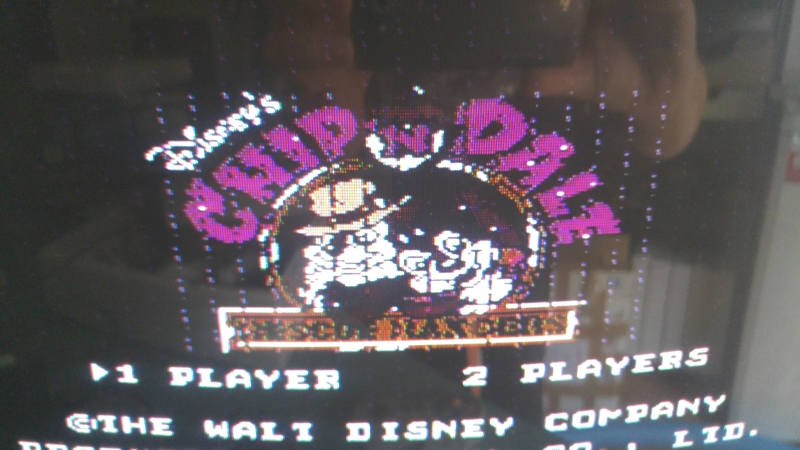
The answer was fairly straight forward. The RGB cable I have here uses the composite signal for its sync. The SF-1 does not seem to output a composite signal at all instead it uses the combined HV sync signal on pin 3. Hooking this up instead gave me a nice picture on my test monitor which confirmed the SNES was working great.
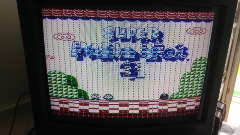
So whats happened to my picture on the actual TV unit?
It turns out the SNES outputs separate Luma and Chroma signals to the TV for its picture and not RGB like we initially thought.
sf1-connectors

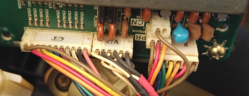
The connector marked ‘VD’ is the video signals. The black wires are all grounds and the white wires are signal. One of the wires however is the audio output. So there is Luma, Chroma and mono audio on this connector.

Now I know the signal isn’t RGB I can pretty much assume that the ‘S-ENC’ (BA6952F) is used to generate the signals i’m missing.
Using the scope I couldn’t find any valid signals coming from the chip. In my haste I was about to write the chip off but as the output signals were really weird I traced all of the pins. I found the GND on pin 2 wasn’t connected at all and it should have been. I tried reflowing the pin but still no connected so I added a jumper wire to the GND point next to it.
20160518_205235

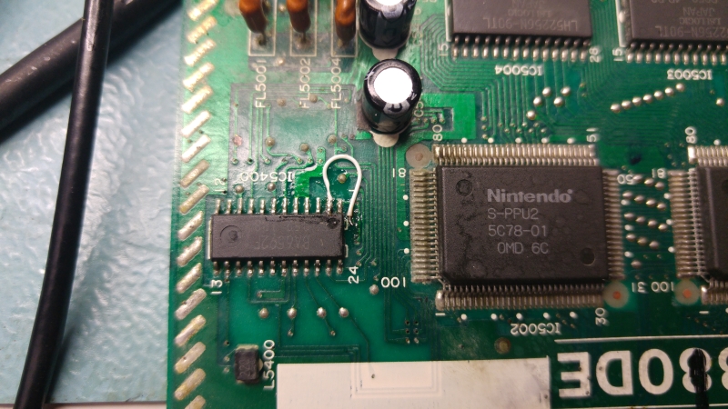
I was a little nervous about patching it as if the original track (that ran under the chip) had burnt out then what had happened to do that? It could have been a manufacturing defect, Ive seen a couple of those in my time but ground connections are generally quite big compared to signal traces. I didn’t want to remove the whole chip just to check for a burnt trace so I just check resistance between GND and VCC. It looked fine so I powered up to test.
21picture

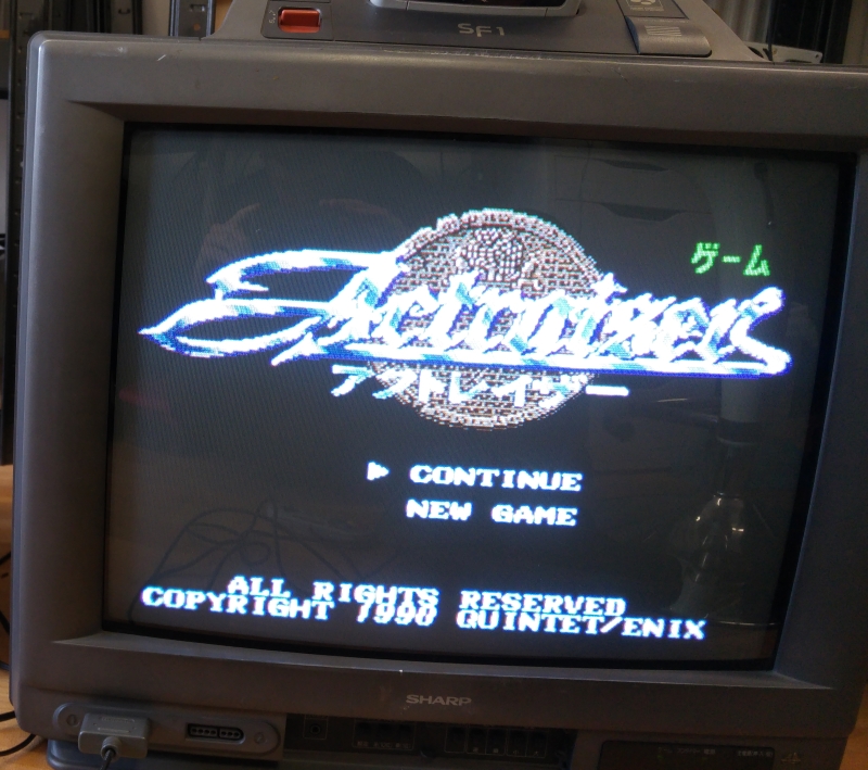
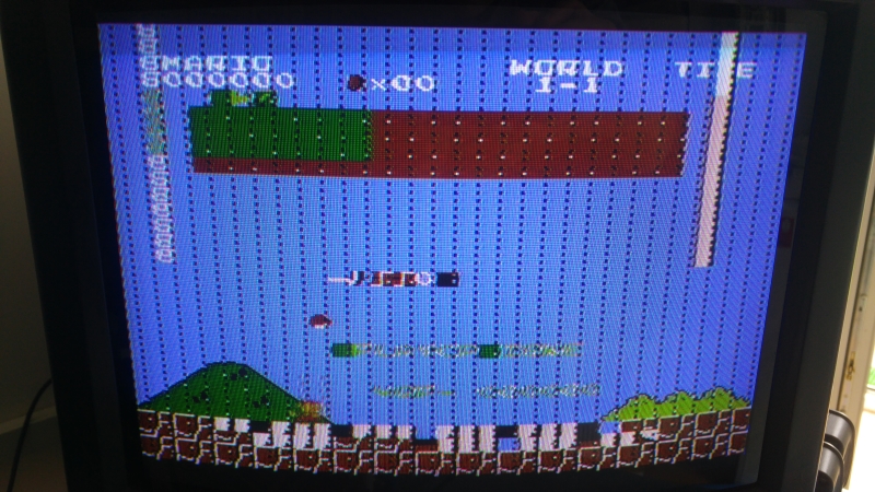
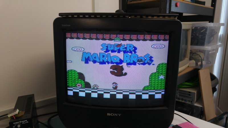
An absolutely perfect picture! Seriously this picture is really good quality.
I tested all the controls and they seem to work fine too so time to box this up.

 Posted by at 8:18 pm

Fujitsu FM-TOWNS Marty PSU repair log

 Console Repair Logs, Repair Logs  Comments Off on Fujitsu FM-TOWNS Marty PSU repair log
Jun 172014
 

I got from a German customer this nice Fujitsu FM-TOWNS Marty console.

For the uninitiated FM-TOWNS Marty a Japanese console whose hardware is derived from its “big brother” FM-TOWNS computer.It has some of the coolest perfect arcade ports ever published like Splatterhouse, Bubble Bobble, The New Zealand Story, Tatsujin Oh and others.

As every Japanese device it has to be powered by 100V/110V so European people must use a step-down converter capable to reduce our 220V/240V to proper voltage .

This is what the owner of this console forgot to do by mistake..:)

So, after some seconds the “magic smoke” came out from the console.

Obviously the console did not power at all so i opened it and I immediately noticed some blown components.In particular the main 2A fuse was blown and a 100uF 200V capacitor was literally exploded on its top.The blown fuse was a good sign since it means he made his duty blocking the excessive current flowing in the circuit but the big 100uf 200V exploded capacitor meant  that this overcurrent reached also other components before the main fuse blown up.So, I decided to further investigate.Usually the first component after main fuse and filter capacitor is the bridge rectifier (which, indeed, rectifies the sinusoidal current in continuous one).In my case there was a 600V 1A bridge rectifier marked ‘S1WB S60’, here the datasheet:

https://pdf.datasheetcatalog.com/datasheet/Shindengen/mXqwrsx.pdf

Infact, as I suspected, I tested it with a multimeter and it was shorted.

So, I desoldered these three bad components:

and replaced them with equivalent ones:

Reassembled the console, powered it and got this:


Mission accomplished.

 Posted by at 8:08 pm