Passing Shot (Sega System 16B) repair log

 PCB Repair Logs  Comments Off on Passing Shot (Sega System 16B) repair log
Oct 122020
 

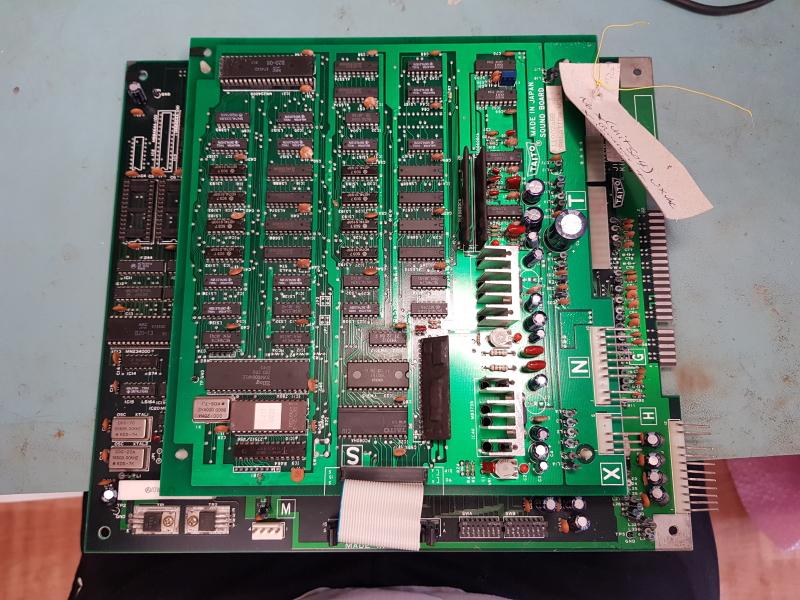
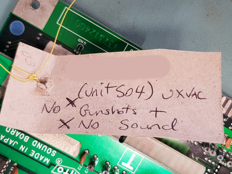
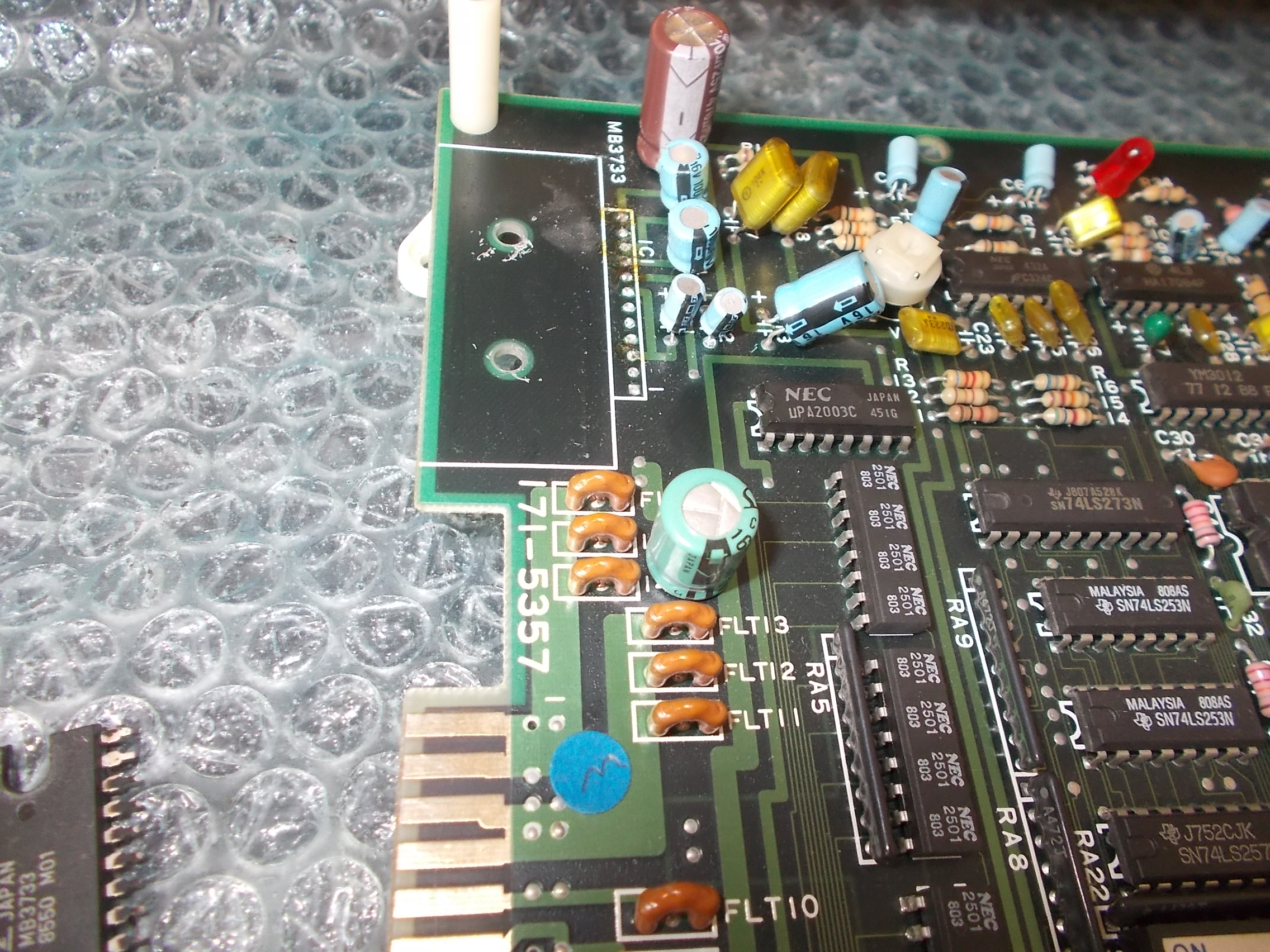
Got an original Passing Shot PCB for repair, as you may know it’s a tennis game released for System 16B hardware by Sega in 1988.

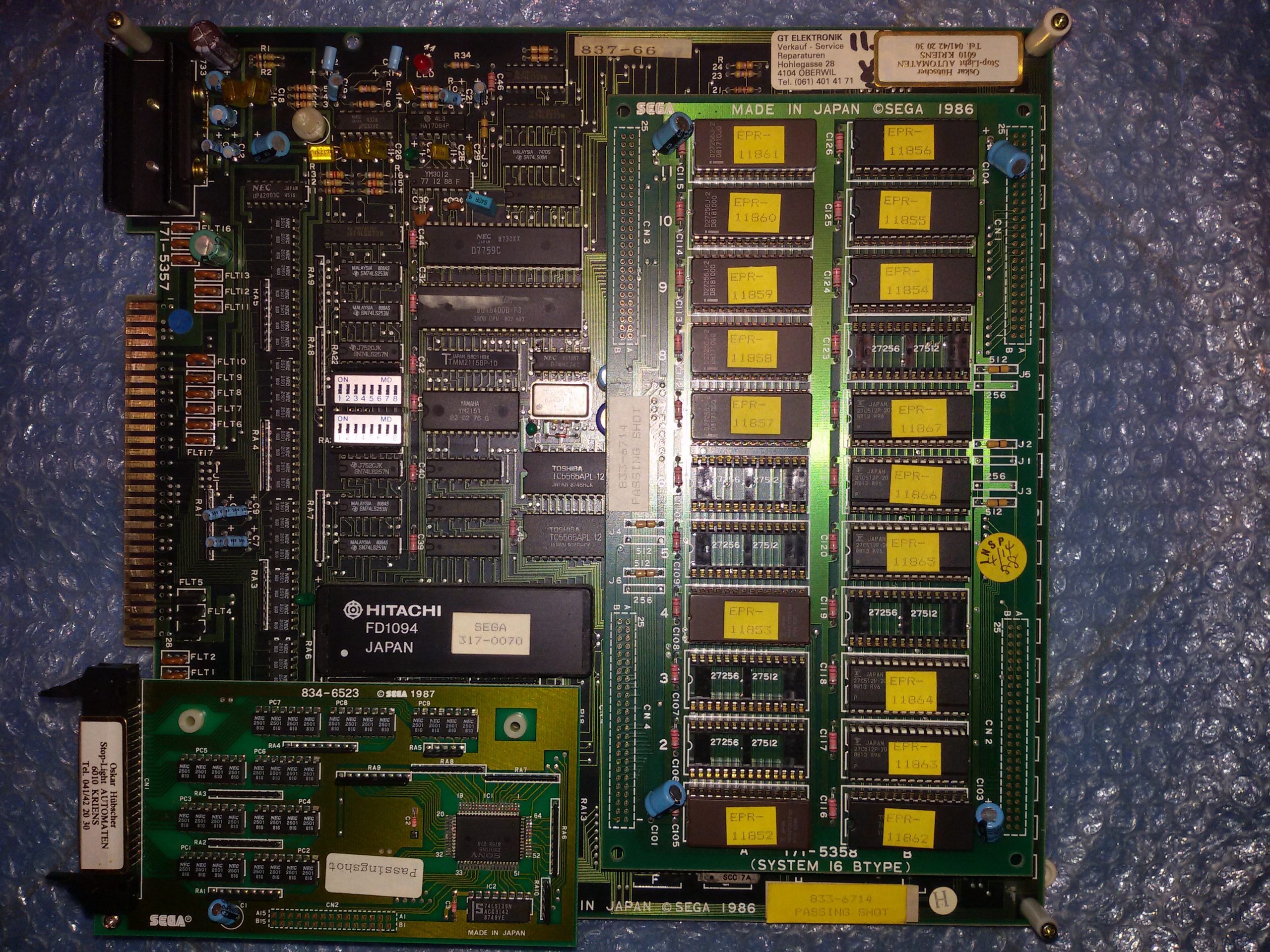
Board had its ‘FD1094’ battery-backed custom CPU module which was still alive since the board booted but sound was missing at all:

These are the times when an audio probe really comes in handy in diagnosing the fault helping you to figure out the nature of the lack of sound (if digital or analog).So I fired up this tool and started to listem to various points of the audio circuit :

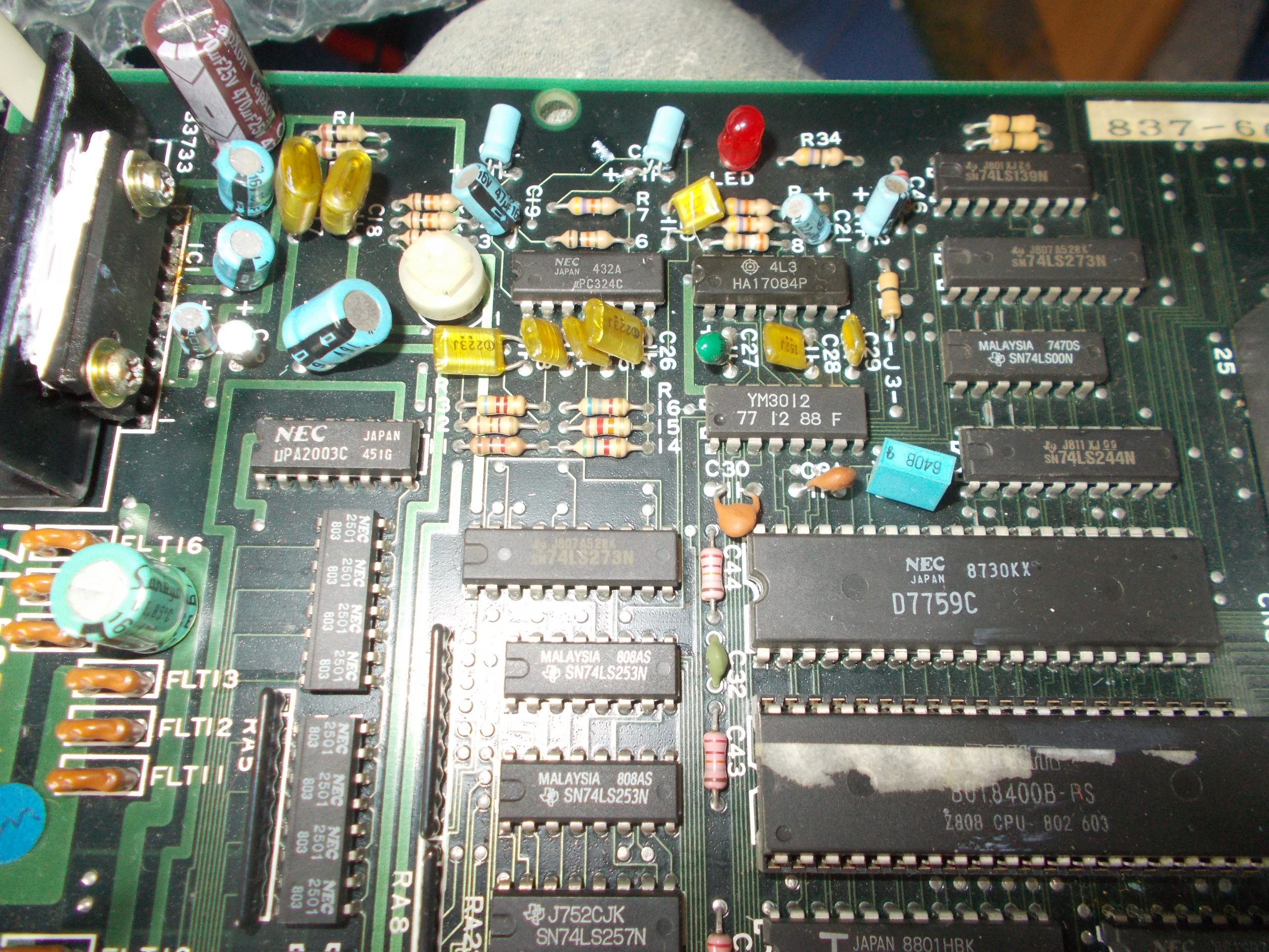
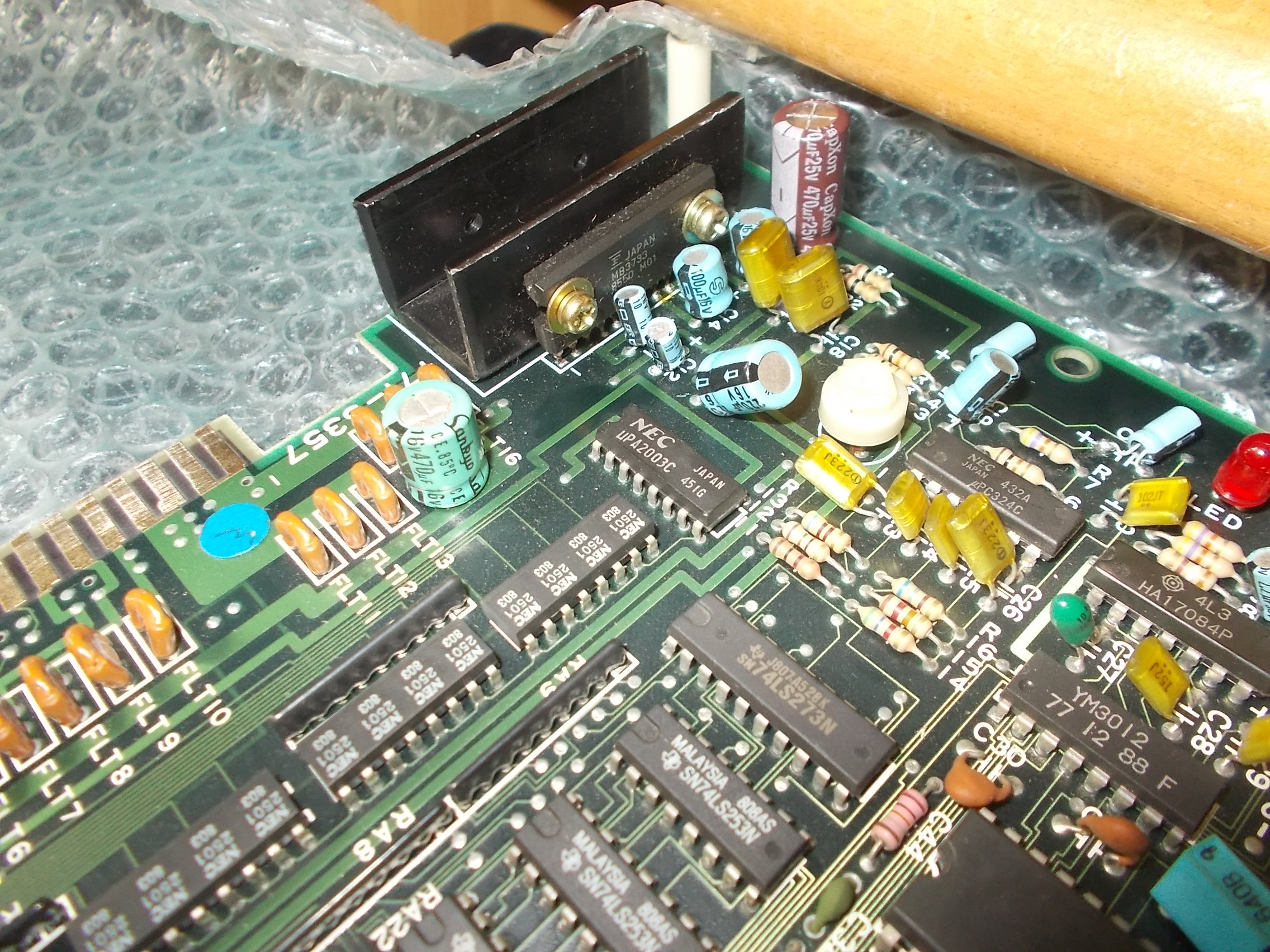
For first I probed the outputs of the YM3812 DAC and I got sound from them, this meant the fault was in the analog circuit.Looking at schematics I followed the path, the sound was still present on the input of the volume potentiometer :

But then it was silent on the output which gives the signal to the Fujitsu MB3733 amplifier :

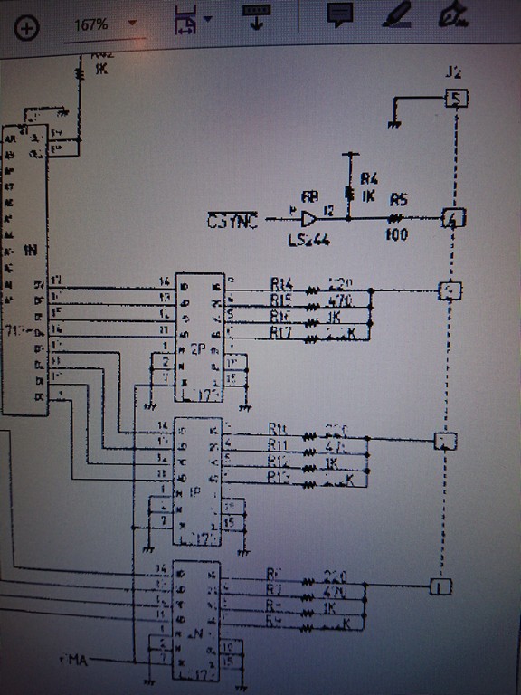
Schematics shows there is nothing between the output of the potentiometer and the input of the amplifier (apart from a 10uF electrolytic capacitor that was tested as good)

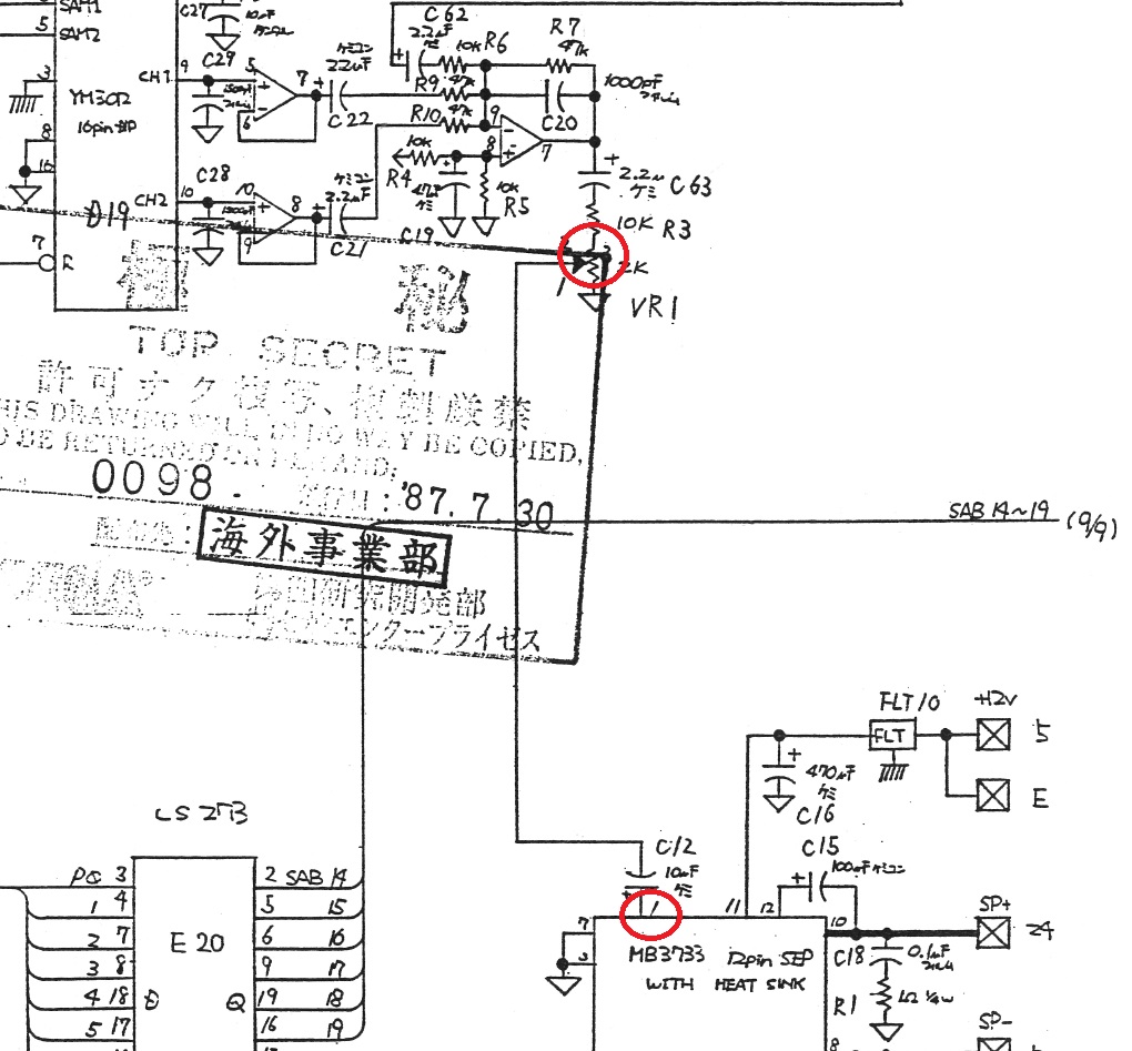
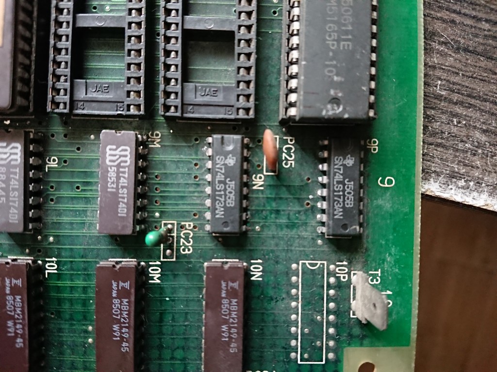
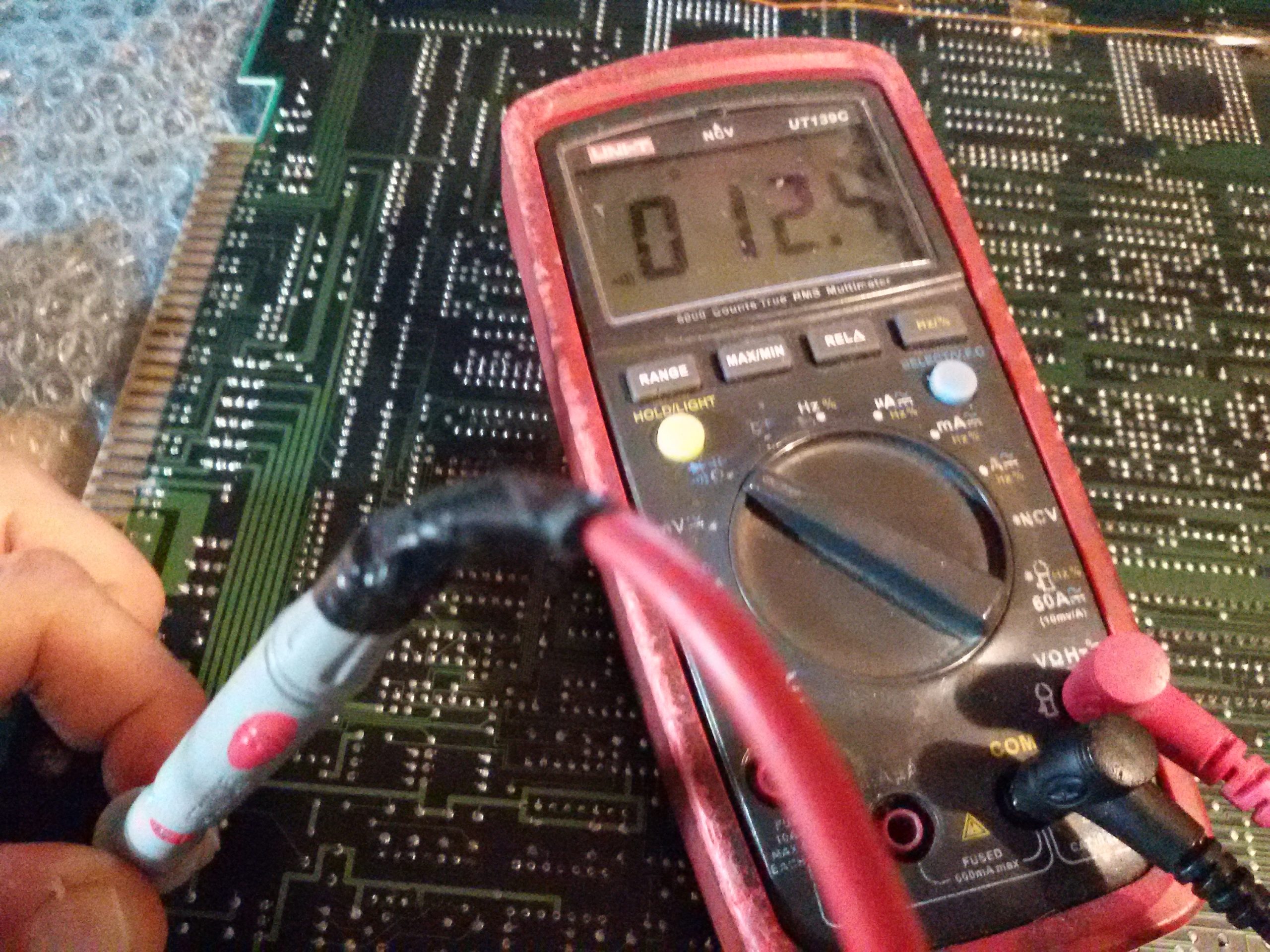
Metering the amplifier I found that pin 1 ( the input which takes the signal from the potentiometer) was almost shorted to pin 11 (+12V supply), there was only 12.4 Ohm of resistance :

The amplifier was likely bad so I removed it :

And replaced it putting also some thermal silicon grease for a better heat dissipation :

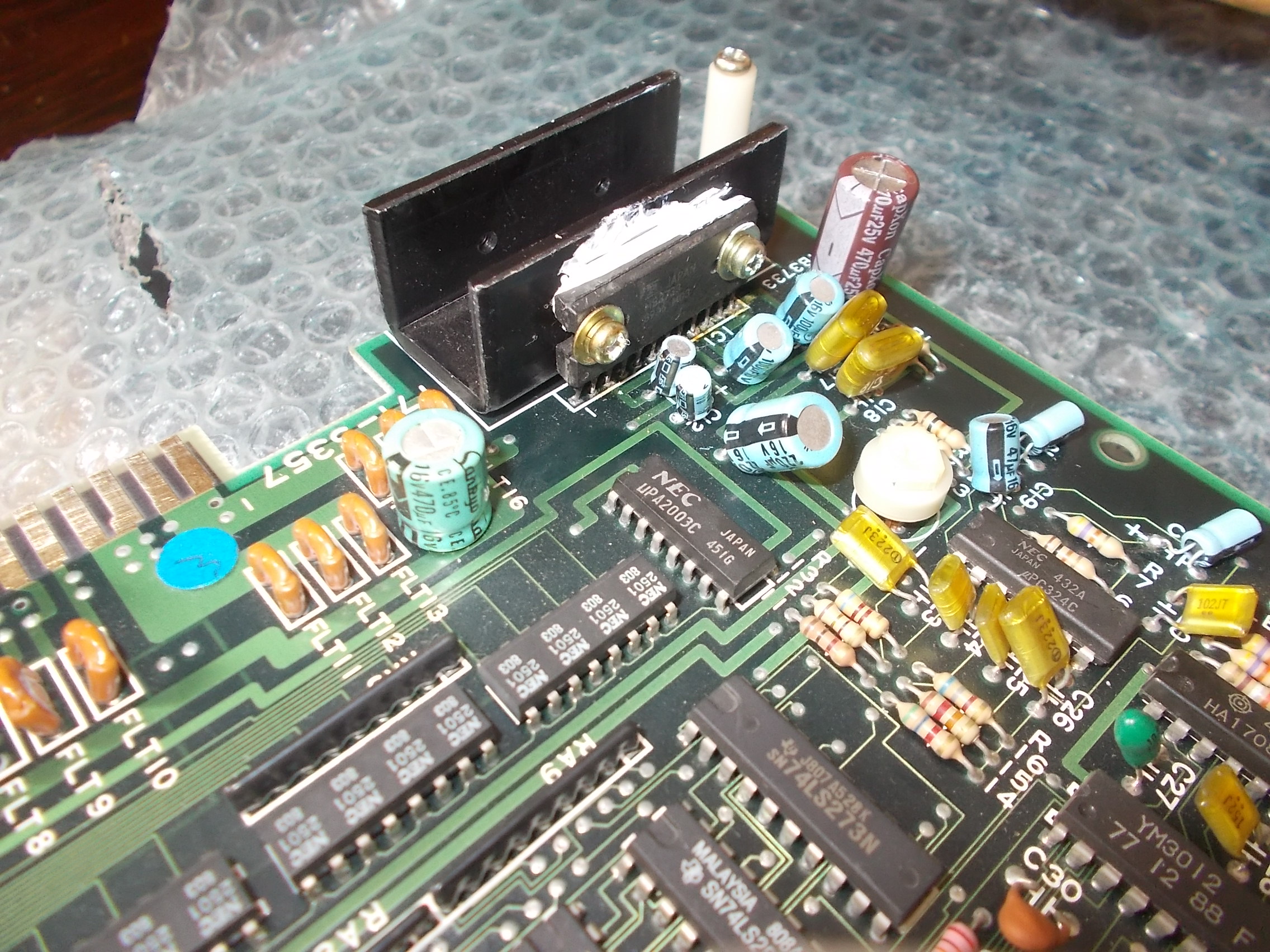
I powered the board up again and the sound was back.No other issue found hence I could declare this board 100% fixed and working.


 Posted by at 3:51 pm
Apr 132020
 

Yet another Operation Wolf repair and this one gave me trouble.
First test we had watchdogging. All ROM’s checked out fine in the programmer and seeing nothing else obvious I removed the work RAM both of which failed.

Now on boot up I got a screen seemingly running game but all the screen was garbage.

Probing the data lines of the screen RAM show pretty much all of them across two RAM chips were dead. I desoldered and replaced them both.

Now I got a running game but the colours were messed up

There are two 74LS245’s attached to the data lines of the colour RAM at location IC78 & IC90. Probing these revealed stuck bits on IC78. Replacing this gave me perfect results on the colour test screen in test mode but dull colours in game. Other issues in-game showed me all the sprites were missing and the screen doesn’t scroll when entering a game.

Stupidly I chose to ignore the colour issue and concentrate on the other two (I will get back to this later).
The sprite and scrolling issue worried me because these areas are related to the PC080SN and PC0900J custom chips.

Paulcan69 sent me a scrapper PCB so I could rob the customs off it if needed so I started out by replacing the PC0900J.

Replacing this brought my sprites back but the scrolling issue was still present.
I didn’t enjoy replacing that IC so I started checking around to see if the scrolling issue could lie somewhere else.
I found nothing wrong so removed the PC080SN custom and replaced it with the spare but it made absolutely no difference. A lot of work time and effort for nothing.
I spent time over the course of the next few days looking into this but found nothing.
Eventually I got sick of looking at the washed out colours on screen and replaced IC90 to fix the last of the colour issues.
I couldn’t really believe it when this fixed my scrolling issue as well.
I still don’t understand why this chip caused the scrolling issue but I’m really glad it did.
All issue are now fixed on this board.

Onto the sound PCB.
The original sound PCB that came with this board was a complete write off. Every chip I pulled from this board was broken and both amps were also burning hot.
Among all the other boards that Paulcan69 had sent me he also kindly sent me a spare sound PCB for Muddymusic to have.
There was a sticker on this board saying “No Sound”.
On first test I found that the music played but the volume was really low. Turning the volume up to the maximum made the sound audible but not nearly enough.
I checked the resistance of the volume pot and found that if you move the pot off maximum setting then it read megaohms. I tried cleaning it but it didn’t work so I replaced it.
This made the sounds much better but like with most of the others I’ve repaired some of the samples were scrambled and didn’t stop playing when they should.

I quickly found another 74LS688 that was dead. Replacing this made the sounds stop when they should but the samples on channel A were scrambled.
Looking at the schematics shows where the sample data goes.

Using an audio probe I checked the output at pin 10 of the 5205. The sound was the same. This ruled out issues caused by bad caps and things like that.
Next I checked the 574 at IC33. Both the input and output looked good so moved onto the 74LS157 at IC 44.
Probing all the outputs with a logic probe showed pin 9 was stuck HIGH

Replacing this fixed all the samples.
That’s the last one fixed
Big thanks to Paulcan69 for the spares board. Without it this board would be scrap too.

 Posted by at 9:54 am

Operation Wolf repair log #4

 PCB Repair Logs, Repair Logs  Comments Off on Operation Wolf repair log #4
Apr 112020
 

Another Operation Wolf repair!
This one belongs to Frothmeister on UKVAC.

Again, we have a nice little fault label

So to start with there was no sound. I did a couple of signal checks to see if commands were being written to various IC’s but saw none of them so I just removed the RAM which of course failed.

Fitting a new RAM brought the sounds back but the samples were garbage

Samples are all stored in the 40 pin MASKROM.

I attempted to read the MASKROM as a 27C400 EPROM in my programmer but it gave me errors

As I had a scrap sound board here I swapped this ROM out and retested.
Samples were now restored but I had the same issue as in a previous repair where the sounds started playing and never stopped.

Time to check out the comparators.
I quickly found the comparator with a stuck output at location IC18

Replacing this fixed my faulty sample playback for this one but I found another by playing sample 2E.
Using the same technique I found another dead 688 at IC39.

To determine which channel the game uses for various samples I use the wonderful MAME debugger.
If you look at the memory map for the sound CPU in the MAME source you can see the addresses that get written to to set the START and STOP values.

Address ranges $B000 – $B006, $C000 – $C006, $D000 – $D006 & $E000 – $E006 are what we are concerned with so set some breakpoints in the debugger and fire up the Operation Wolf test menu (dont forget to set the debugger focus onto the sound CPU).
Play the sounds that cause issues and see which address gets written to.

Now look at the schematics

From here we need to work out with signal is address $C000.
A15 & A14 give us an address of $C000. the 74LS138 at location IC14 gives us the enable line for the channel. A15 enables the 138 itself and A14 selects the relevant output, in this case its input C which enables (active LOW) pin 11. This in turn enables IC54 which as you can see from the signal names is channel B.
Following the schematics further we find the 74LS688 comparators responsible for this

Probing the only output on those comparators (pin 19) and playing the sample shows me which one isn’t toggling. In this case it was IC39.

All fixed

 Posted by at 3:47 pm

Operation Wolf repair log #3

 PCB Repair Logs, Repair Logs  Comments Off on Operation Wolf repair log #3
Apr 102020
 

Another few Operation Wolf boards in at the moment. This one is from Unit504.

There is a nice little tag on this telling me the faults which really helps me keep all these boards together and where to start looking.

First job was to look into the gun shot register issue.
I did a quick test and could see the screen flash when the trigger was pulled so I knew that wasnt the fault
Following the circuit I come to the 74F74 IC which is used to latch the gun co-ordinates.

I normally wouldn’t start looking at this part but it was already socketed so decided to pull the chip and test it. It failed an out of circuit test.

I replaced this with a 74ALS74 and it seems to be be fine.
Now all the gun shots register as expected.

Next onto the sound.
None of the sounds were working at all and I didnt believe that all the seperate circuits for making sounds would be dead so looked a bit closer at the CPU side of things.
First off I checked the ROM and it dumped out fine.
Next the RAM. An inspection of the RAM showed signs of corrosion

I removed and tested it and thankfully it failed

Looks like that corroded pin has broken contact somewhere. Anyway, replacing the RAM brought all the sound back to life and completed this repair.

Metro Cross repair log ( same hardware of Baraduke)

 General, PCB Repair Logs  Comments Off on Metro Cross repair log ( same hardware of Baraduke)
Mar 302020
 

The game at first didn’t boot due to the watchdog circuit being triggered.

There were 4 work srams by Toshiba and first one from left was faulty.

Unfortunately soon after , game started to reset again and the second sram from left failed.

The PCB had then all sprites in a single row and was missing the text on the upper and bottom area and soon after it losts also the BLUE component

Decided to start from the easy part and restored the missing colour.

Green and blue components are generated by the PROM @ 1N.

Signals were good so the fault was in the 74LS173@2P which had all output stuck at 0V

After changing the TTL I restored the blue component.

The missing text was due to the 74LS195@6L , while checking it I saw that the text reappeared but glitched

After changing it I finally had again the text


To restore the sprites I decided to concentrate on the \HSET signal on the sprite address generator circuit.

This signal comes from pin 22 of CUS35 and it was always stuck LOW. I took another CUS35 from a Baraduke  board and the problem remained.

So I decided to look at the other side and checked two 74LS173@9N and 9P

I shorted for a brief moment the \Hset signal to 5V and the sprites were correctly drawn again and the signal was oscillating.

But I noticed that some sprites has some glitching on colours.

I decided to replace both of them

Board was 100% fixed


Of particular note is that all the faulty TTLs were by Texas Instruments ( not Fujitsu!) and of uncommon type.

It seems Namco had a stock of these ICs to be used on an hardware design 😉

Please note also that CUS35 is 100% compatible with CUS48 from later Namco system 1 games.