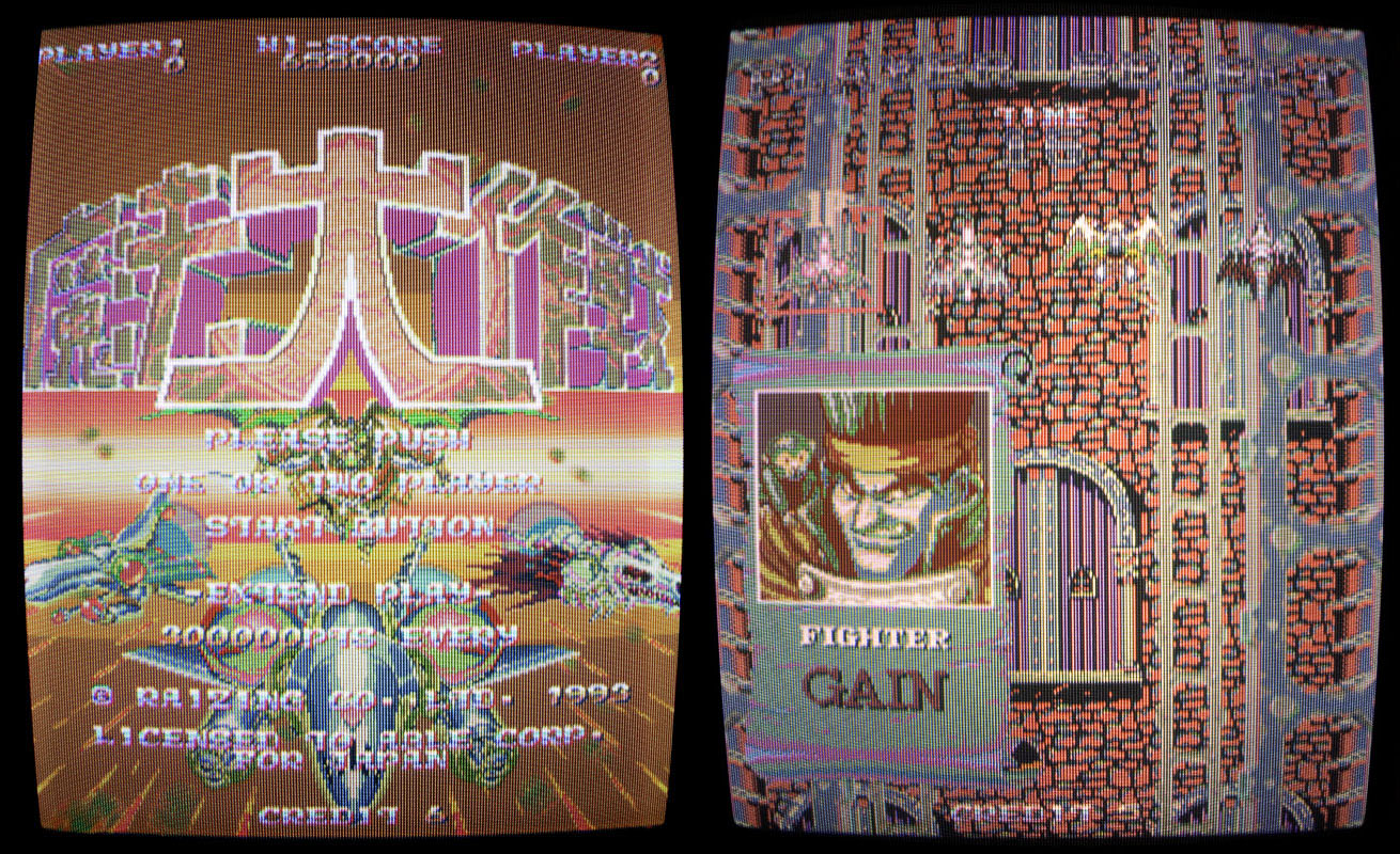
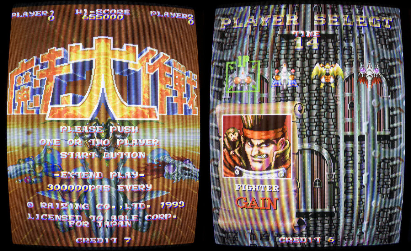
A friend got a Mahou Daisakusen (japanese version of Sorcer Striker) board with faulty graphics.
It was playing fine with sound but there was an obvious color palette problem.
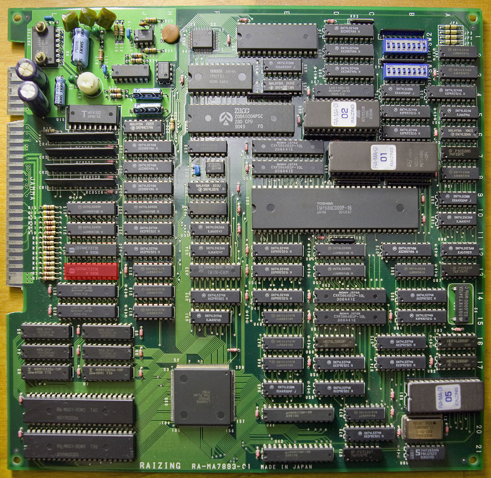
I started looking at signals around the color outputs of the PCB and quickly found weak signals on the 74HCT273 at location U12. Piggybacking the chip with a working 74LS273 fixed the colors immediately.
I replaced the chip… Board fixed.
Here is a picture of the PCB with the defective chip highlighted in red:
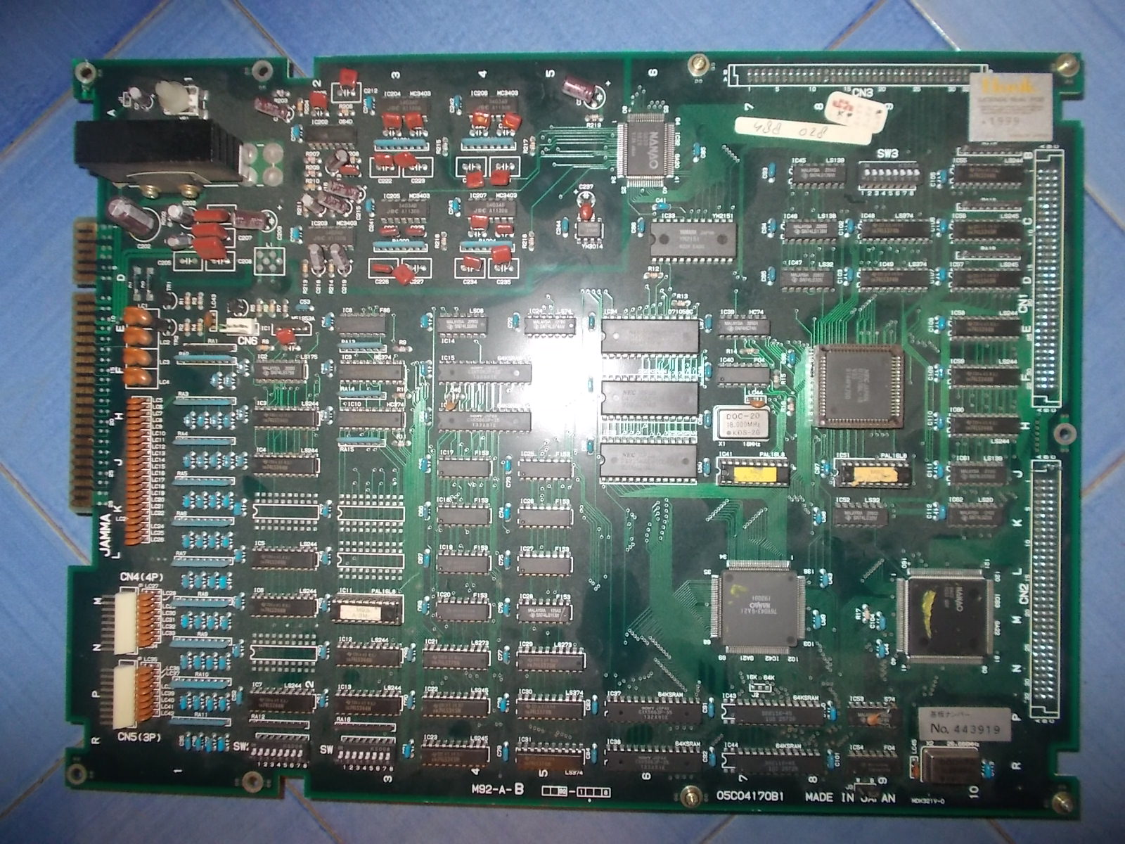
Received some Irem 92 boardsets mostly for replacing preventively the infamous ELNA brown electrolytic capacitors but two of them were faulty too.
The first was a Cross Blades (japanese version of Blade Master!), board had green ELNA capacitors so no strict need to replace them.
But it suffered from sprites isssue, they were missing some parts:
Pressing the board in the area of ‘NANAO GA22’ custom ASIC restored the sprites :
A closer inspection of this custom revealed three liften pins :
Reflowed them fixed the issue :
The second board was Hook (World version) :
Game booted up but sound was missing, I could hear only a rustling noise.Besides, video had some interferences:
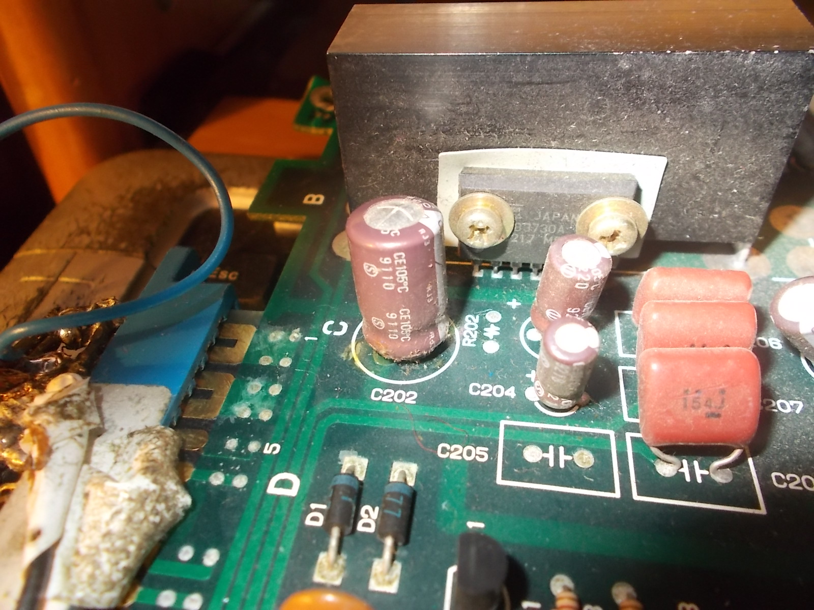
Usually the two issues are strictly related, the cause is some bad electrolytic capacitor in audio circuit which affects video output too.The board mounted ELNA brown capacitors which are well known to age poorly.Sure enough :
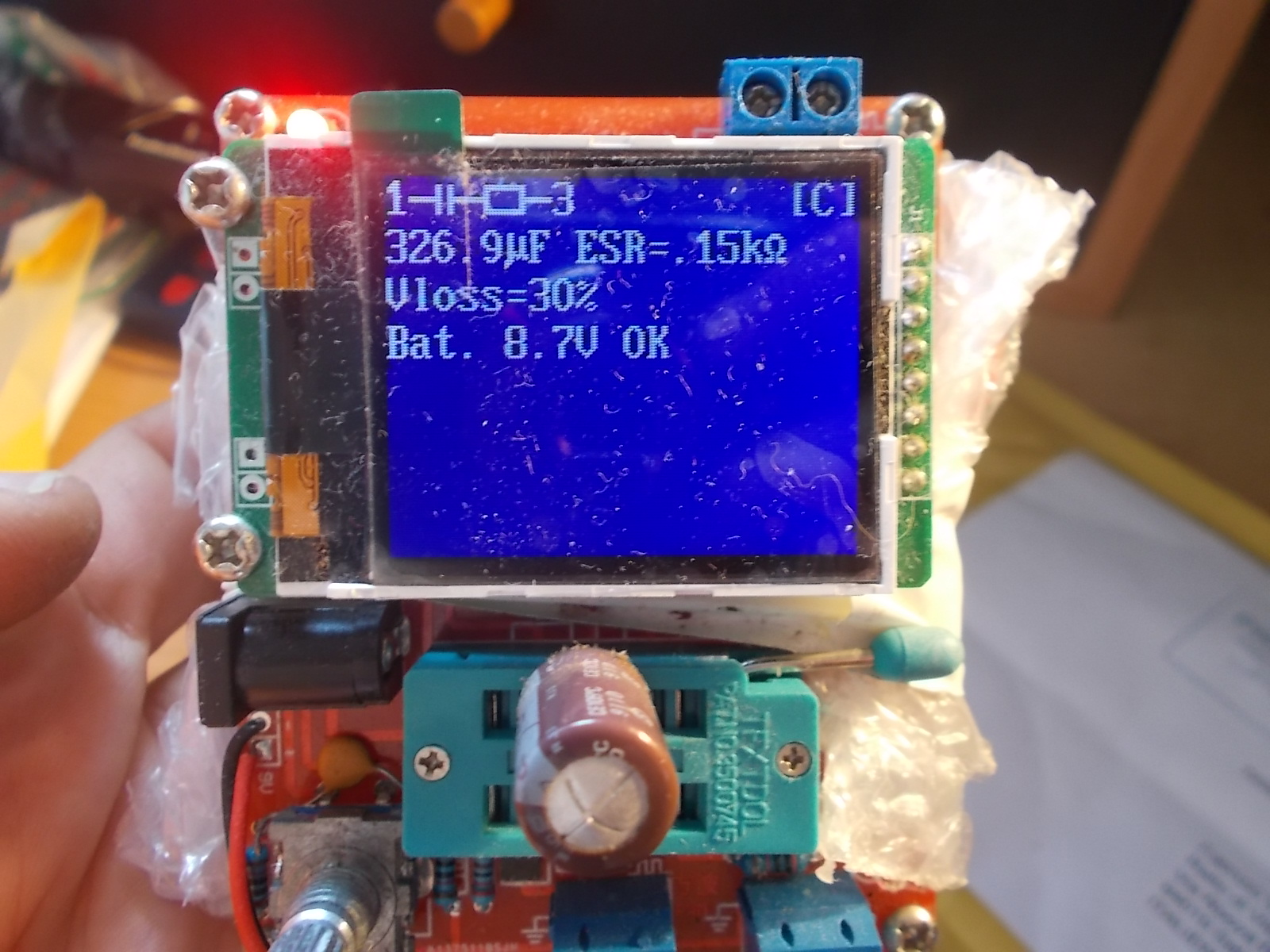
The 470uF 25V @C202 was clearly leaking, this capacitor is used as filter for the +12V for the amplifier, this explained the issue.Measuring it out of circuit confirmed it was bad with an increased ESR of 150 Ohm :
I replaced this and all other electrolytic capacitors, this fixed board completely:
Here’s for reference the capacitors list with value and location :
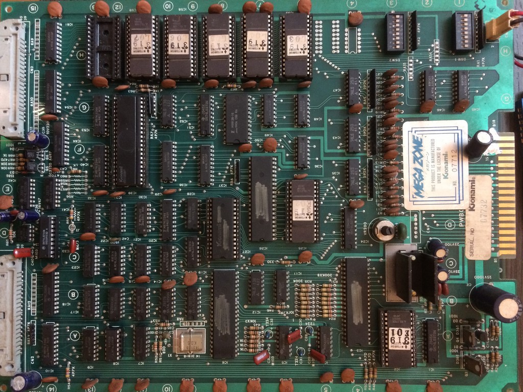
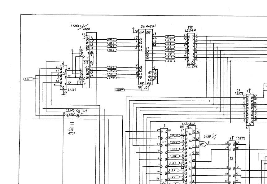
Game was resetting over and over right after the first stating screen without even the possibility to see the diagnostic screen “RAM ROM OK”
The code was running and the watchdog was triggered by some event which I eventually found in a faulty 2114 SRAM @E15 on the video board
Marked in red on the actual pcb:
After changing it, the boot process went on until it displayed RAM and ROM OK but it reset again just before screen with the white grid.
At this time I was complete blind , missing any programming skills I couldn’t check what the code missed to go on.
I had a suspect on the sound part and after checking the clocks on the 8039 MCU I noticed it was completely missing.
The oscillator was working correctly and from the schematics I could see that the clock for the 8039 and the AY is generated using some 4bit binary counters 74ls293, very difficult to find on other boards.
Probing pin 9 of 74ls293@A12 it was stuck high while on pin 10 I had the clock.
I proceeded to test it out of circuit but was tested good.
Not sure about the reliability of the tester, I found a Starforce boot which use one 74ls293 and I installed it in a socket on megazone.
Still reset and no clock from pin 9
The output of the IC@A12 goes to pin 8 of a 74ls240, therefore I decided to test pin 8 of IC @D14 against +5V and it gave me a short.
After changing it the game finally booted without any other faults
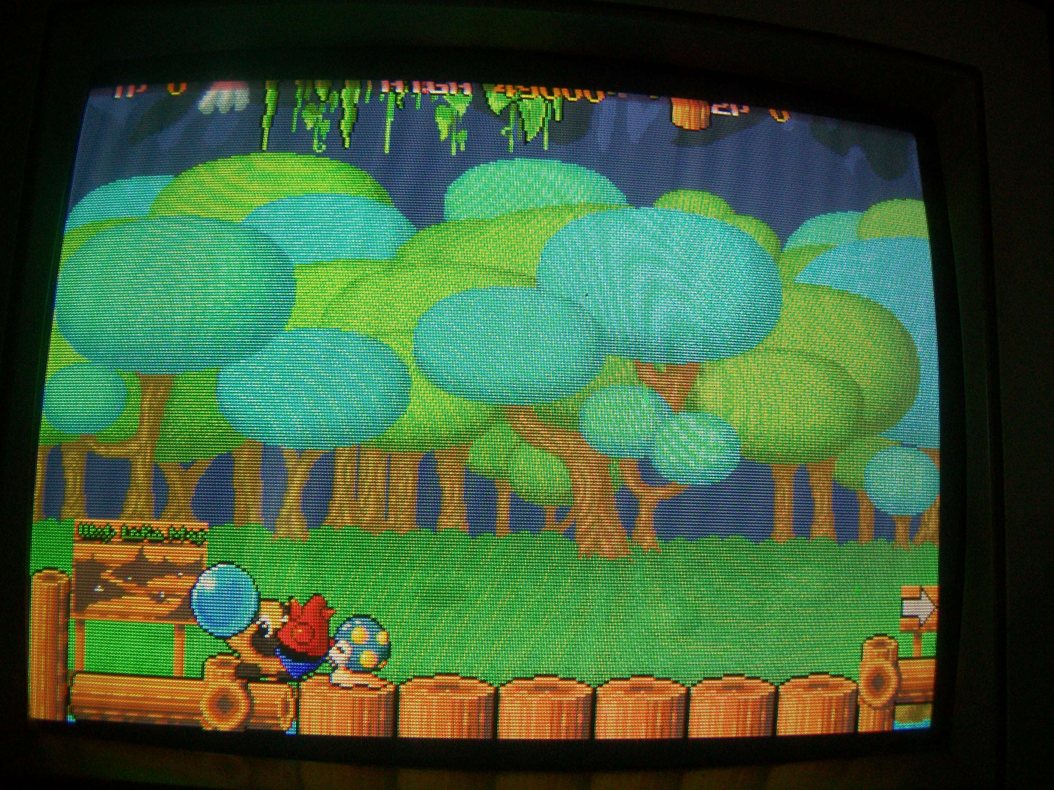
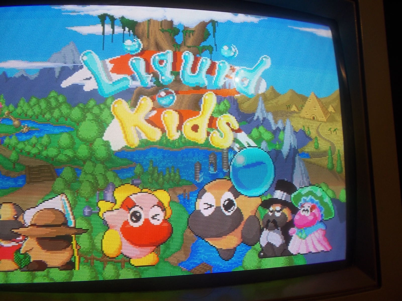
This is a quick double repair log of Liquid Kids, a cute platform game release by Taito in 1990 on “F2 System” hardware.
The first PCB:
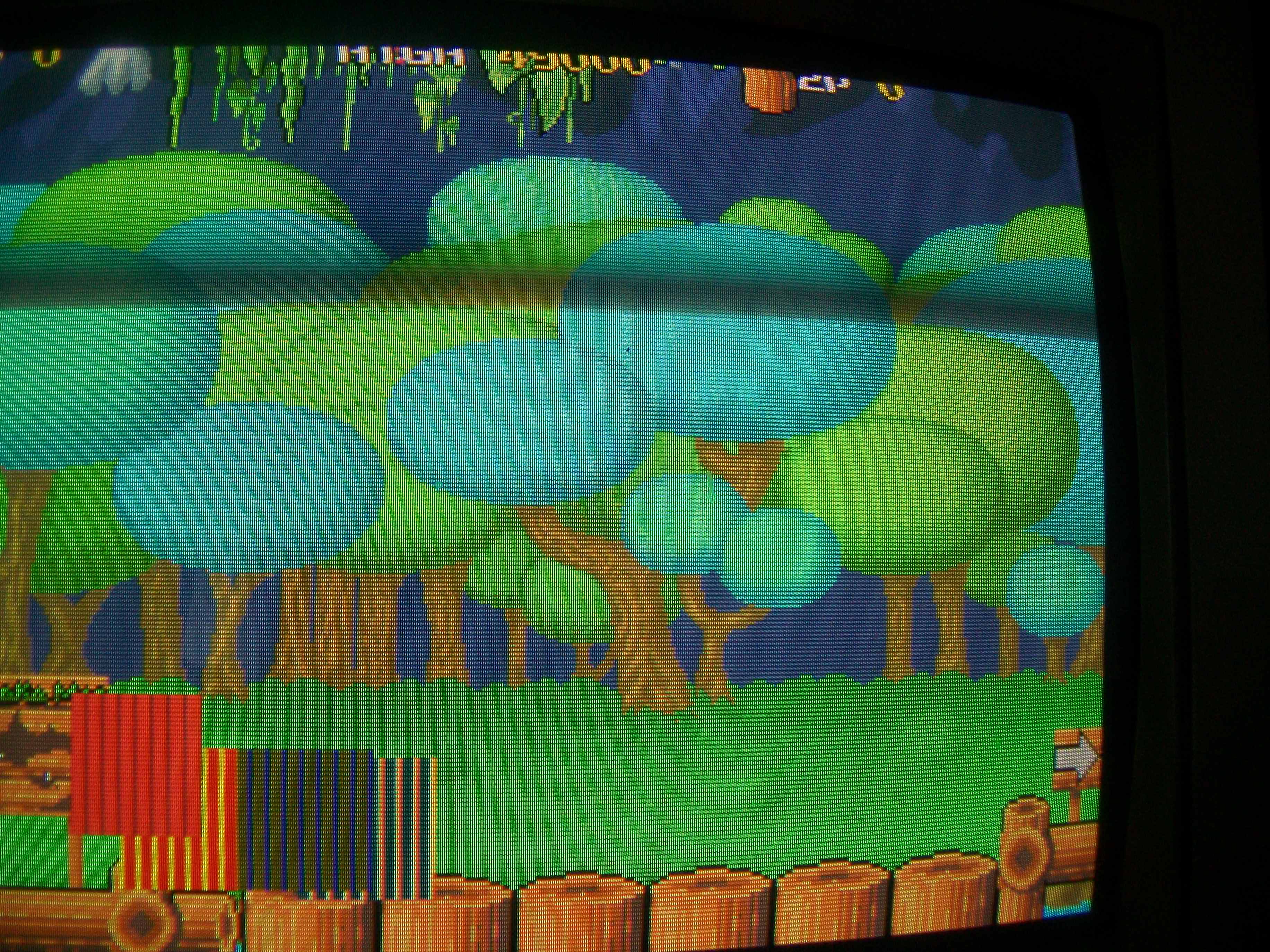
It played fine but sprites were blocky:
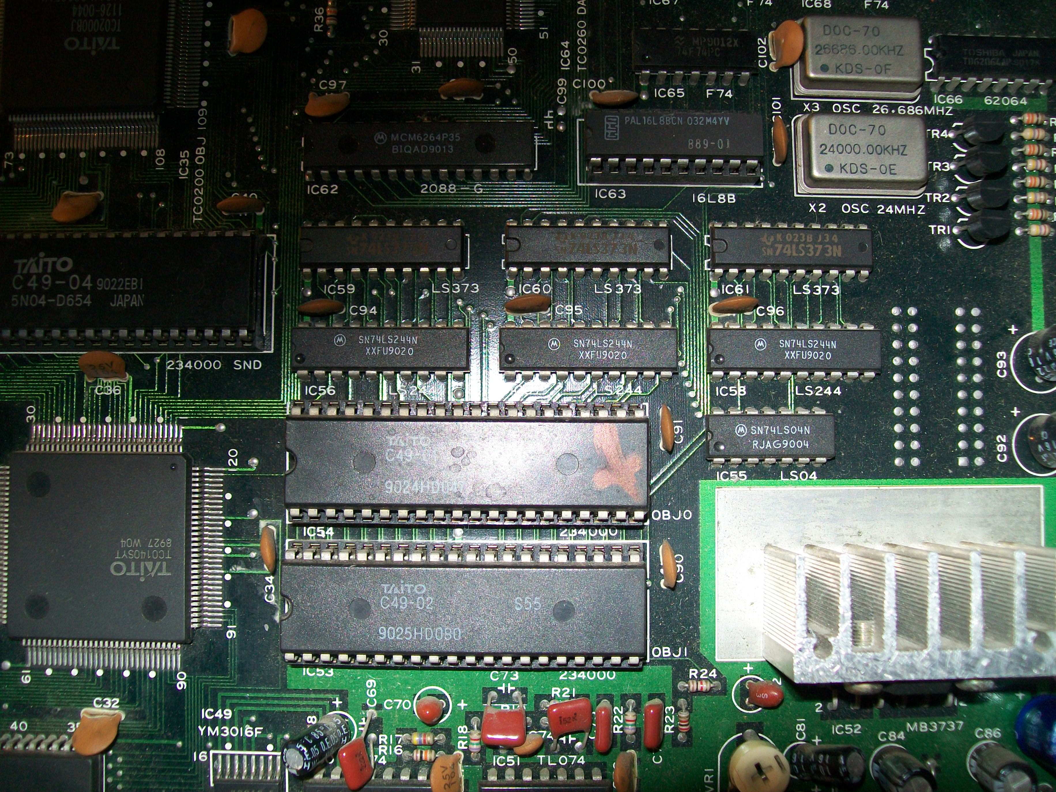
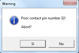
This Taito board like many other uses 4Mbit MASK ROMs to store GFX data, they are well known to be prone to failure.When I went to read the one @IC54 containing sprites data my programmer complained about pin 32:
The device was internally damaged and its dump was bad so I replaced it with a pin to pin compatible 27C400 EPROM, this fixed the issue and board completely.
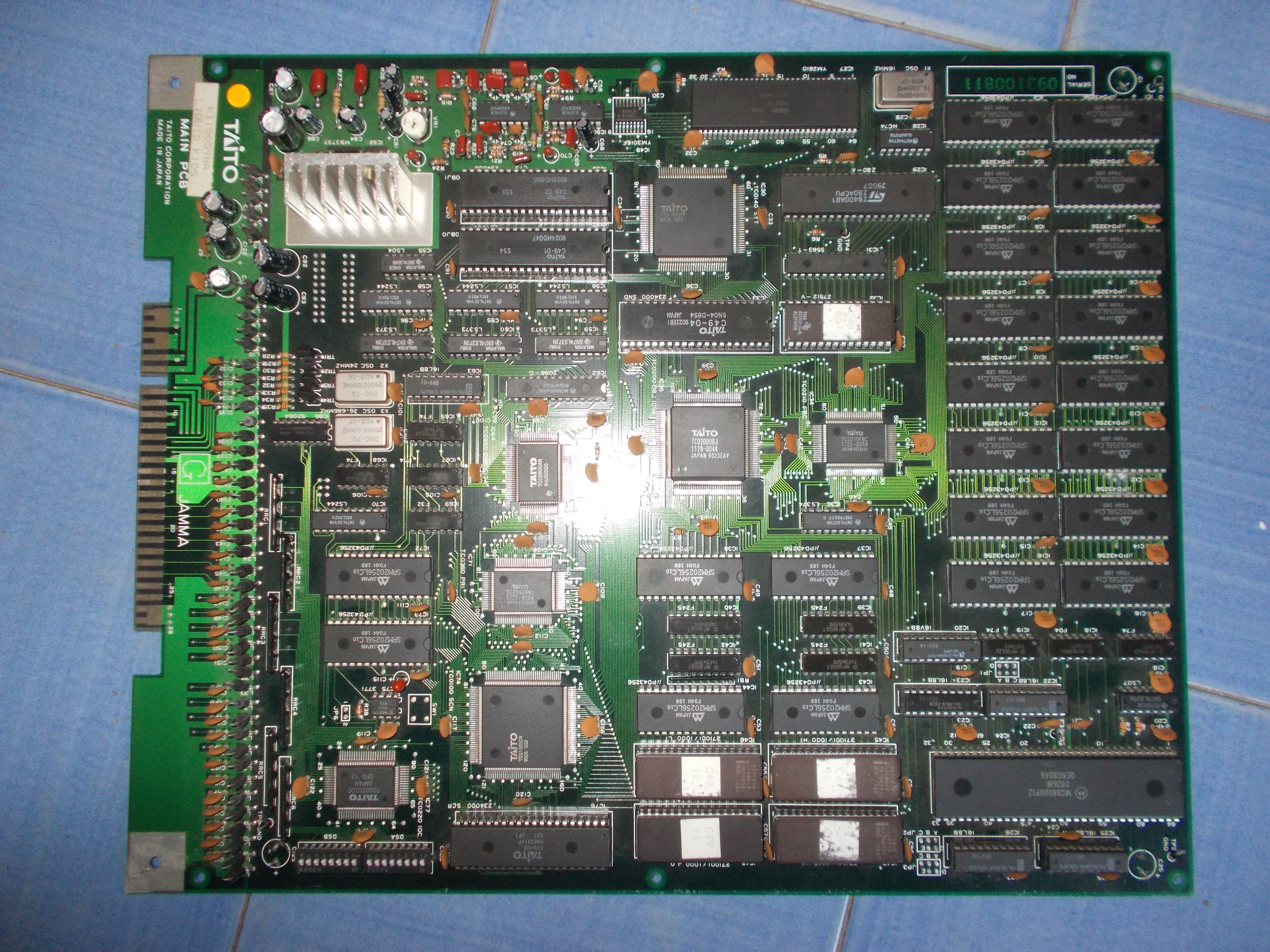
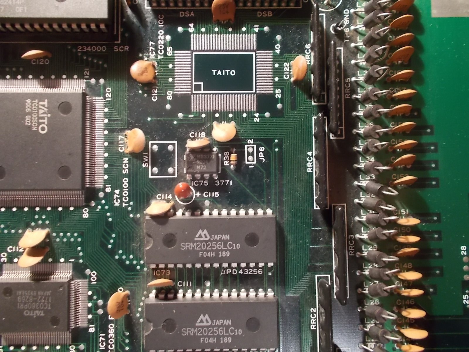
The second PCB:
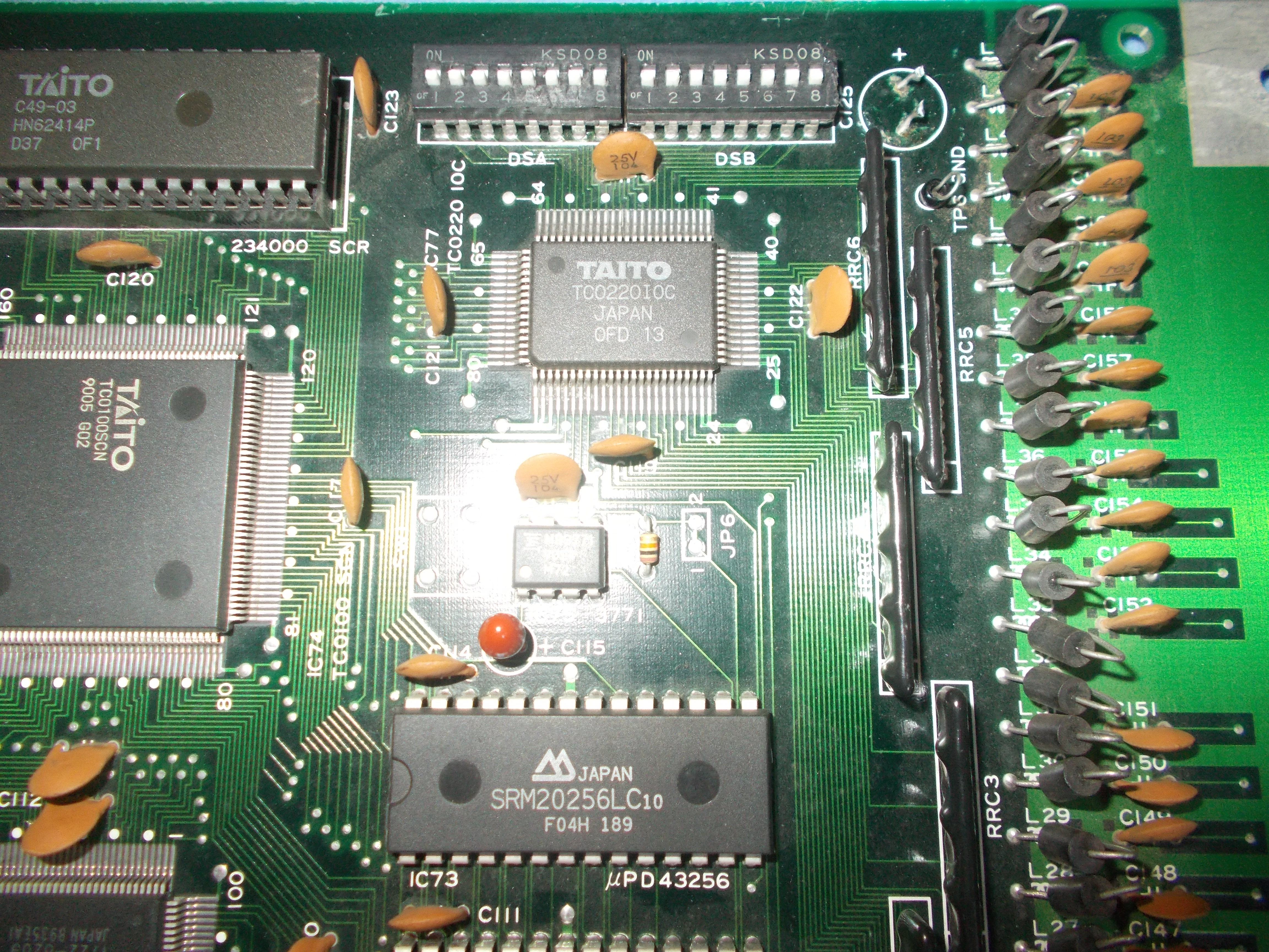
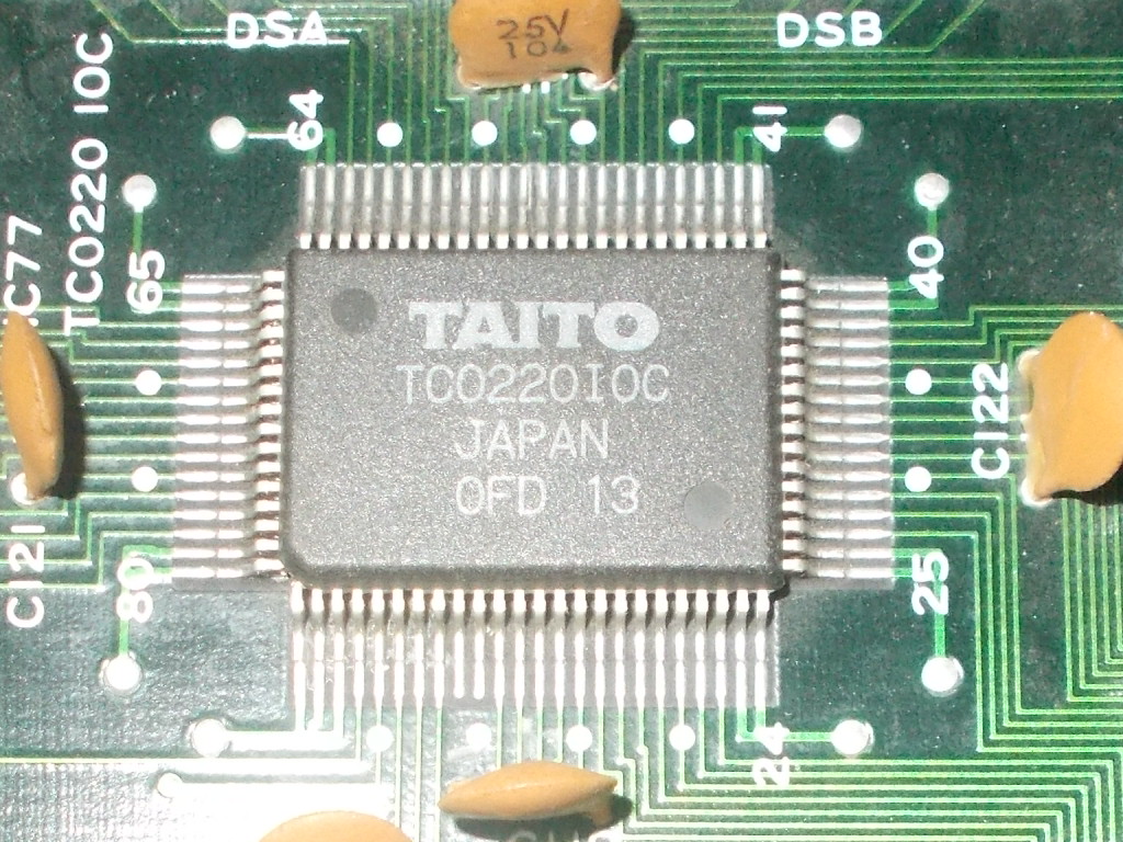
It was dead giving just a black screen on power up.Probing the main 68000 CPU revealed the /RESET and /HALT lines were both asserted all the time.The /RESET signal (and /HALT which is derivated from the first) is generated by the usual circuit made of a voltage monitor (in this case an MB3771) and some external components but it’s not directly tied to 68000 but it goes to the custom IC marked ‘TC0220IOC’ (which handles I/O too) which outputs it on its pin 8 :
Lifting this pin confirmed the custom was generating a stuck /RESET signal.Since by-passing the IC is not possible (device is addressable by main CPU) the only choice was replacing it, this is for sure another part very prone to failure, I can say from my experience that when a board that uses it is not booting then this custom is most likely bad :
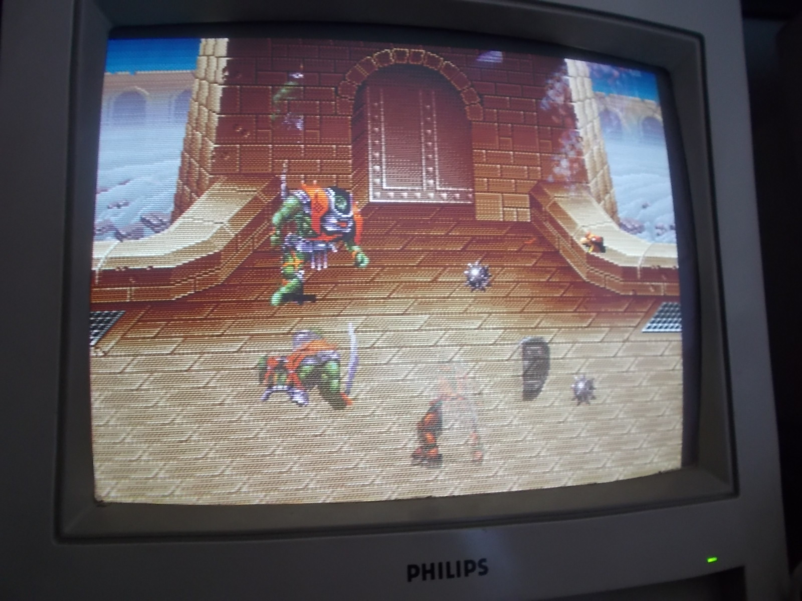
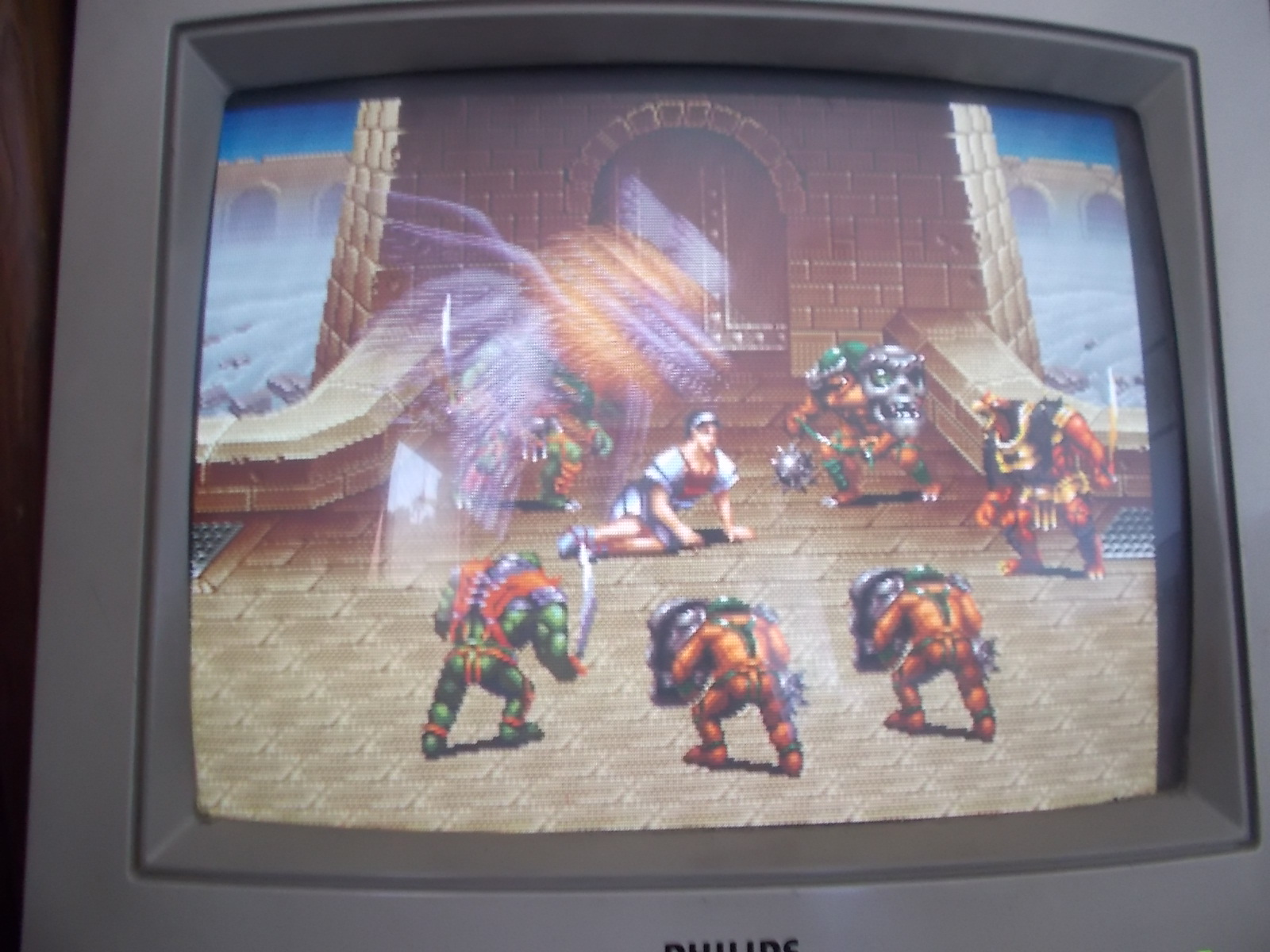
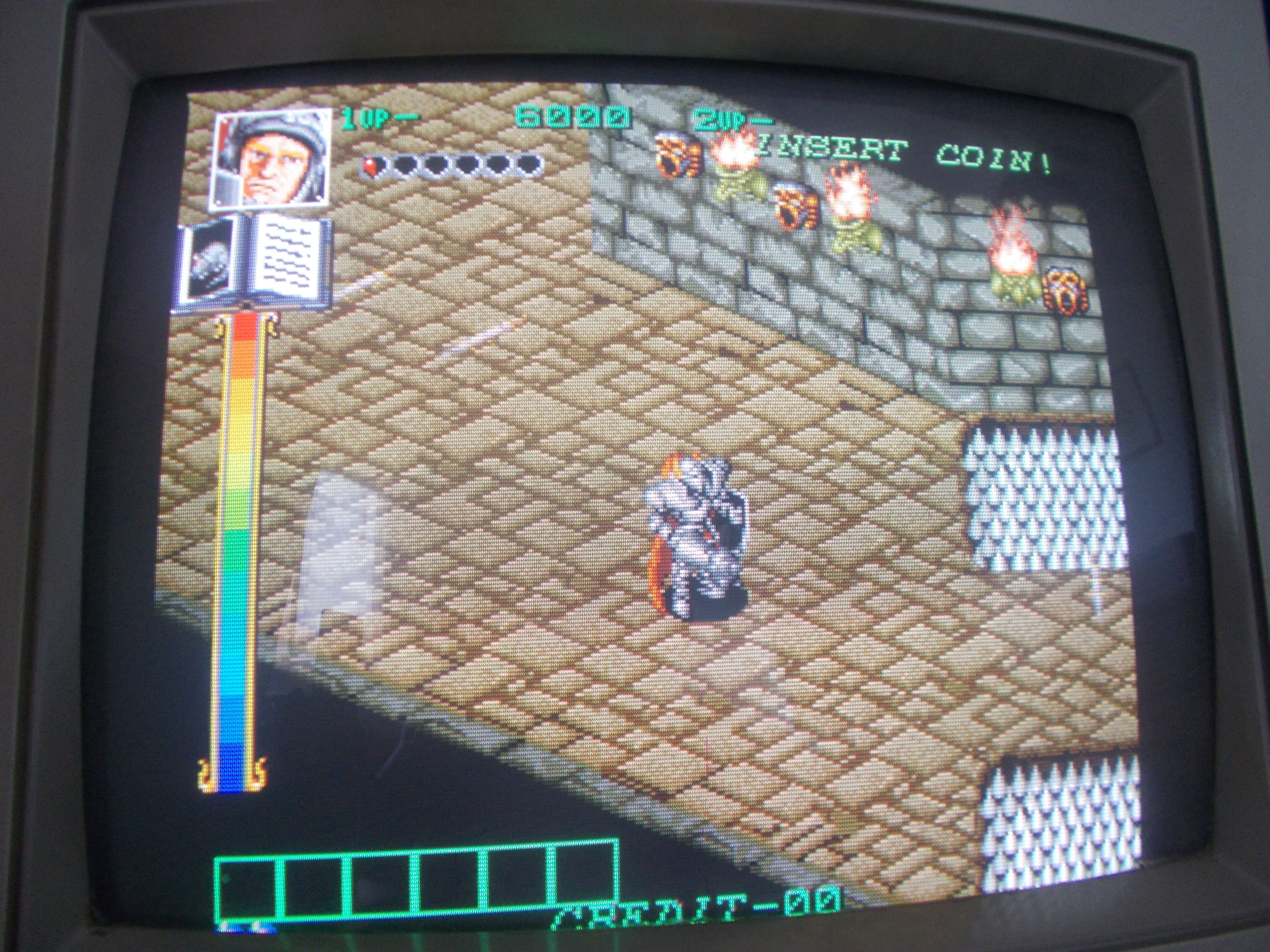
Got a Dark Seal PCB in a lot of faulty boards recently acquired.For the uninitiated Dark Seal (also known as Gate of Doom in USA) is an action game with isometric perspective and R.P.G. elements released by Data East in 1990.
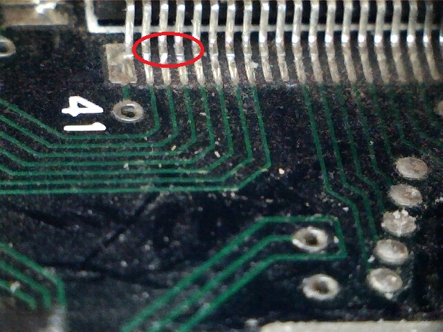
My board did nothing upon boot giving a solid black screen.Applying pressure on one of the custom ’55’ (the one in the upper right corner) restored the video output, a closer inspection revealed some lifted pins so I did a reflow.I got stable video output now and could play the game but image was rolling, this was a clear sign that SYNC signal was missing :
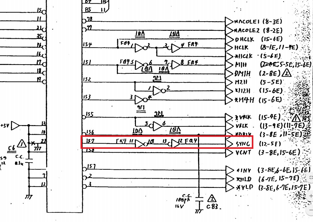
There are no documentation available but other Data East games share same design.Desert Assaul for example, here’s a snippet from its schematics :
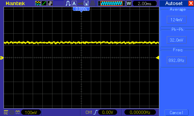
As you can see SYNC signal is generated by pin 157 of the custom ’55’ and then inverted two times by a 74LS04 before reaching the JAMMA edge.I could measure a good signal on this pin :
but nothing on pin 13 solder side of JAMMA connector :
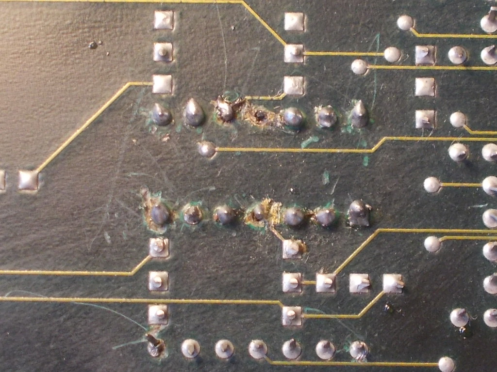
So the problem was in the middle.Looking at solder side of board I noticed the area of the 74LS04 that inverts the SYNC signal has been badly reworked in order to socket the TTL itself, some rivets were ripped off:
Signal was present on pin 1 of the 74LS04 and correclty inverted on pin 2 but, following the scheme of Desert Assault, it was absent on the adjacent pin 3 (pin 4 is connected to JAMMA SYNC pin via a 47Ohm resistor) so the trace between pin 2 and 3 of the inverter had been severed by the previous attempt repair.I simply bridged these two pins restoring the SYNC on JAMMA.But, once I got a stable image, I noticed the blue color was very strong and after some time it disappeared causing a yellowish screen:
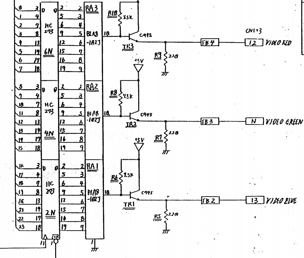
Color generation circuit is pretty the same of Desert Assault:
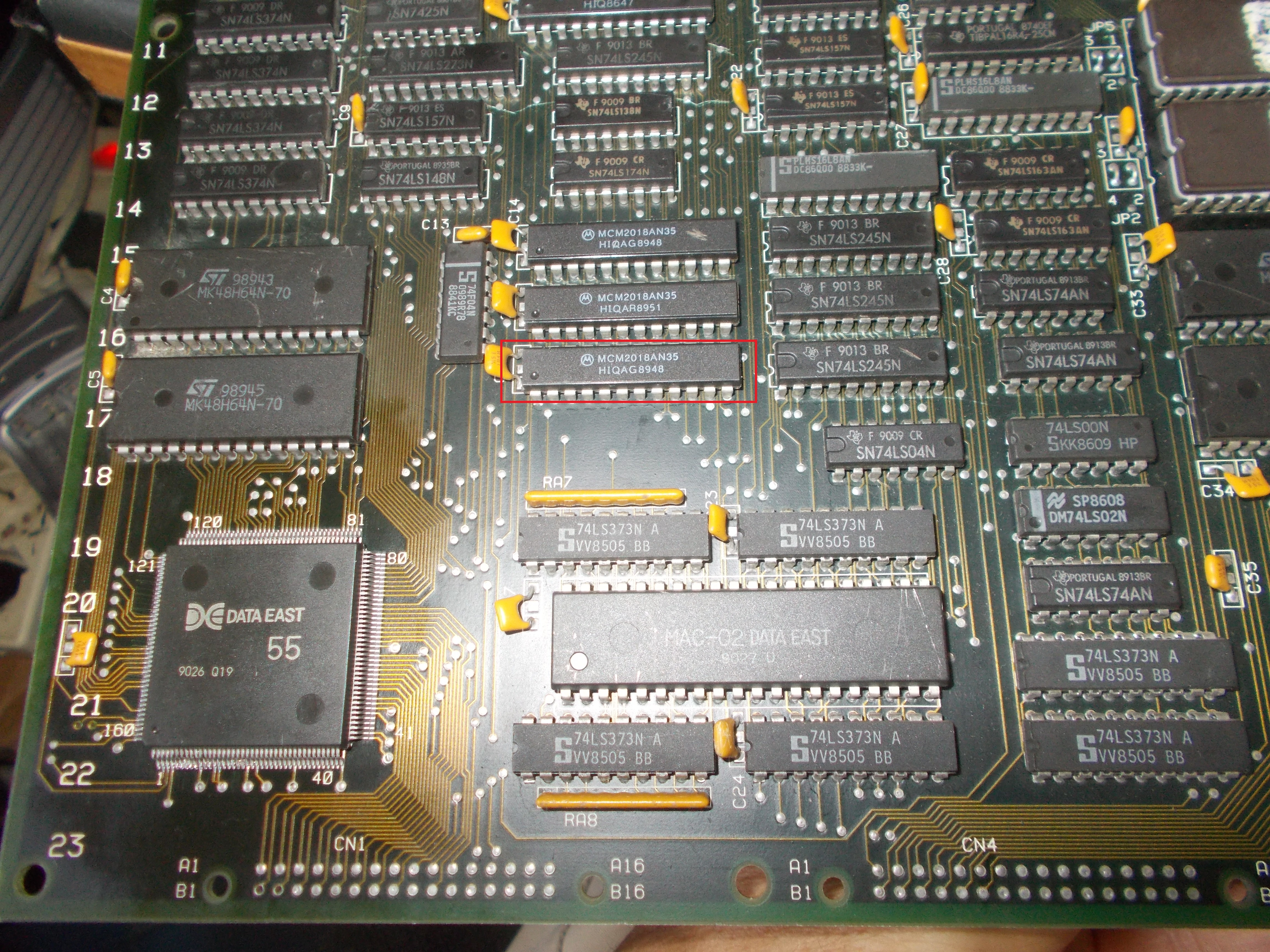
As you can see bits of the tree colors from the 8-bit latches are converted to analog by a resistor ladder and, lastly, each color is amplified by an NPN transistor.Signal was absent on the emitter and base of transistor so problem was upstream.Going back I found nothing abnormal until I got to the palette RAMs, three 2018 :
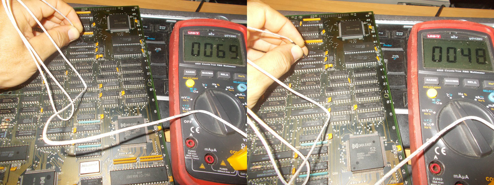
The one highlighted in the above picture was burning hot to the touch, with a termocouple I could measure an external temperature of 69°C compared to 48°C of the other two (RAMs in palette circuitry run usually warmer than other since they have greater power dissipation due very fast access time, 35ns on these ones)
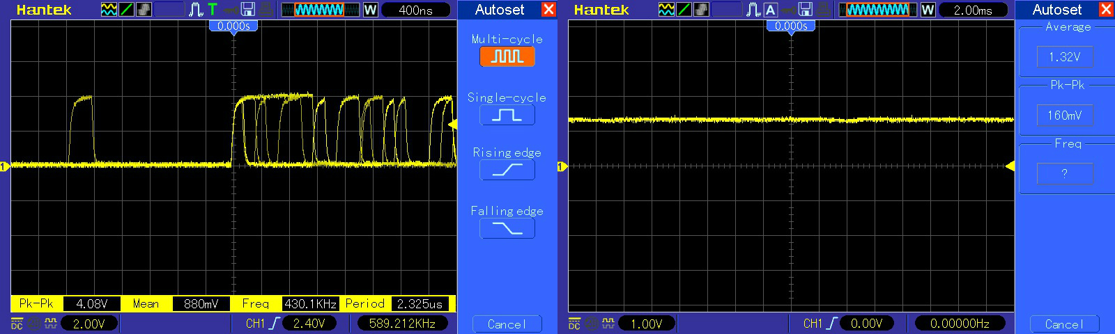
Analyzing the suspicious RAM with a scope revealed all data lines were stuck low (healtly signal on left, bad on right of the below picture)
Once removed, the chip failed the out-of-circuit test: