SEGA ST-V repair log #2

 PCB Repair Logs, Repair Logs  Comments Off on SEGA ST-V repair log #2
Dec 292016
 

I’ve had the same Sega ST-V motherboard in my collection for quite some time now. Randomly one day, the board booted up with completely scratchy / static audio. At first I suspected the capacitors since the fault developed in my possession, however they were not the culprit. I put the board in storage to return to it another day.

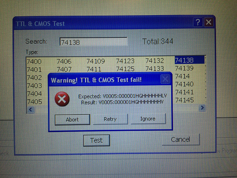
Fast forward a few months, my friend Jassen pinged me asking if I could look at his ST-V. He described his board was having scratchy audio (same fault my board is exhibiting). To my surprise, Jassen informed me he contacted Ken @ irepairsega.com, and was advised that the TDA138 DAC Audio IC was likely the culprit. We all know Ken is a GOD when it comes to Sega repairs, so this information was likely spot on…

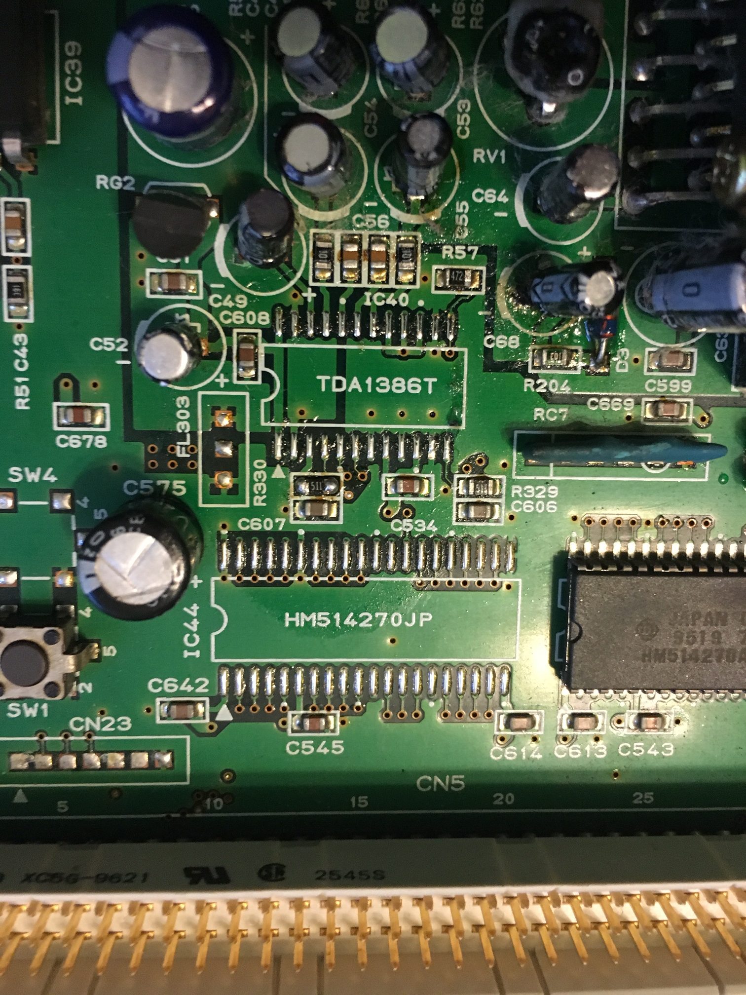
We ordered a couple of IC’s (one for each ST-V). Once they arrived from China, I pulled out the hot air gun and went to work:


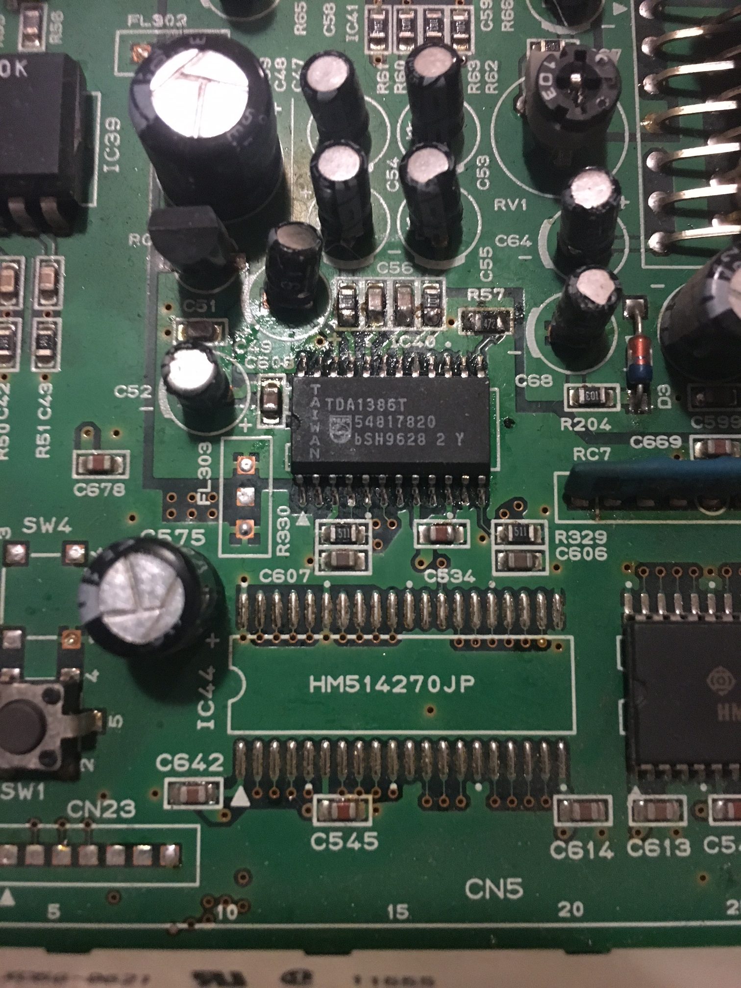
I successfully installed the DAC’s (one on each ST-V motherboard):


SUCCESS! The scratchy samples are now completely gone (on both boards), and the audio is nice again. Being that I repaired two boards with the exact same fault at the same time, if you experience and ST-V with bad audio, start with the DAC!

The Simpsons repair log #2

 PCB Repair Logs, Repair Logs  Comments Off on The Simpsons repair log #2
Dec 292016
 

Let me preface this by saying I’ve been really lazy about blogging my repairs this year. I found some free time today and decided now is a good time to post some of my accomplishments. All of the following repairs were performed through out 2016, but not documented until now. Enjoy!

I received a faulty Simpsons PCB off of ebay for a reasonably good price. It was sold simply as not working with the faults not described. Upon receiving the board, I observed it was in very good condition and a worthwhile repair candidate. When I fired t up, the graphics were REALLY bad! As you can see, the backgrounds and most of the sprites are missing:

I was able to run the rom test and self test, all IC’s reported as good (so I was confident there is not a ram or rom issue at hand). I turned to the mame source code to better understand what each of the Konami Hybrid IC’s are responsible for in the graphics section. I learned that 053247 and 053246 are responsible for sprite generation, and decided they would be a good starting point. Fortunately I had a dead XMen parts-PCB with both of these Custom IC’s present. I started by swapping 053246 with the donor from XMen. As you can see below, we’re getting better! But its still not fixed… Backgrounds are rendering but the sprites are now missing.


I decided to move on to the 053247 IC, and attempt swapping that next. I learned that these IC’s work in tandem, and if one is bad, there’s a chance the other is also bad.

With both IC’s changed from the donor Xmen board, all graphics are restored!!!


Repair complete, game now plays 100%. I don’t dare imagine the abuse this PCB received that took out BOTH custom IC’s, but I’m glad its ready to play on. Another gem saved from the scrap bin!

Thunder Dragon 2 repair log

 PCB Repair Logs  Comments Off on Thunder Dragon 2 repair log
Dec 242016
 

Got this Thunder Dragon 2 for a repair :

According to the owner, the PCB has suddenly developed a graphic fault, this was confirmed once I powered up the board:

In this close up you can see better the kind of fault:

Some part of foregrounds had missing lines and they were flashing (see clouds in the above video to make an idea of).Not being schematics available, I started to study the hardware and found, that shorting some pins of a CXK5164P RAM @U136 (there are four of them) changed the way the fault appeared:

This is an unusual 22 pin static RAM of 64K x 1-bit manufactured by Sony (usually we encounter 1-bit RAM as dynamic ones) but I could find its datasheet and hence pinout:

All pins were correctly toggling but analyzing with a scope the DATA OUT (pin 9) I found discrepancies with the same signal from the other three RAMs ( good signal on the left, presumed bad one on the right of the below picture):

As you can see, transitions of the right waveform are not regular sign of bad data coming out the device.At this point, I had to order a spare since I had no stock of this unusual static RAM.I had to wait almost a month before getting the right part since at first the seller sent me by mistake some OTP EPROMs.But at the end I received it:

And it was worth the wait since I could finally fix this great shoot ’em up!

 Posted by at 6:08 pm

Snow Bros (bootleg) repair log

 PCB Repair Logs  Comments Off on Snow Bros (bootleg) repair log
Dec 242016
 

We all know that a bootleg is a copy of an original board and often a not perfect one since they could be not well engineered.They can suffers from different issues, the one that occurs most often is an unstable video SYNC.Just like this Snow Brows bootleg:

Board played fine but screen was wavy :

Analyzing the SYNC signal with a scope,  amplitude of pulses seemed a little bit over the standard , +4.16V as average while usually they should be within +4V :


This was most likely the reason why my monitor didn’t like it so I thought about a workaround.Usually it’s suggested to use a 5K Ohm potentiometer set as voltage divider : one terminal to the SYNC signal generated by the PCB, the other tied to GROUND and the wiper (the central one) to the  SYNC pin of JAMMA connector.In this way you can adjust the SYNC signal voltage between the original voltage level and GROUND.I wired the potentiometer in this way and installed it on the JAMMA connector of my supergun.Adjusting it, I got a stable screen but I wanted a permanent solution on the PCB.So I used two resistors as a voltage divider:

In my case I used a 270 Ohm resistor as R1 and a 4.7K Ohm as R2 since, doing a bit of calculation, this should have been enough to bring the signal within standard : 3.93V=4.16V*4700/(270+4700).

I installed the voltagev divider on the solderside of PCB (obviously I first cut the trace going to PIN 13) .

This was what I measured:


My monitor was finally happy with it.End of job.

 Posted by at 3:53 pm

Karate Champ repair log

 PCB Repair Logs, Repair Logs  Comments Off on Karate Champ repair log
Dec 192016
 

I bought this game for my collection.

I had already Karate Champ player vs player but this one was the rarer first version , japanese revision titled Karate Dou.

The game was very dirty and rusty and despite being declared fully working, the sound was completely missing.

The seller proposed a refund by sending back the pcb.

Before taking this road I decided to give a try at repairing it since the schematics for this pcb are available on jammarcade.net (they are not the same as the more common player vs player!) and the hardware was pretty simple.

After cleaning it in the washer machine, I started the trouble shooting

I immediately noticed that all the 7 sound eproms (BE2o – BE26) and the ram beside them had no activity on the data lines.

So I probed the /CE line and it was stuck high for everything.

That means the devices are in standby mode and they cannot output anything.

With the help of the schematics I traced back the source of the problem to IC18, a 74ls138 who outputs were all stuck high despite the activity on the inputs.


After replacing it, I tested out of circuit and the programmer confirmed it was faulty


By replacing IC18 with a good one, the sound was fully restored.

Note: If you have Karate Champ player vs player which use the same adapter, only remember that the older Karate Champ uses also -5V for the pre amps. If you forget to wire it , you get a very noisy and hissing sound.