Ordyne repair log

 PCB Repair Logs  Comments Off on Ordyne repair log
Aug 012017
 

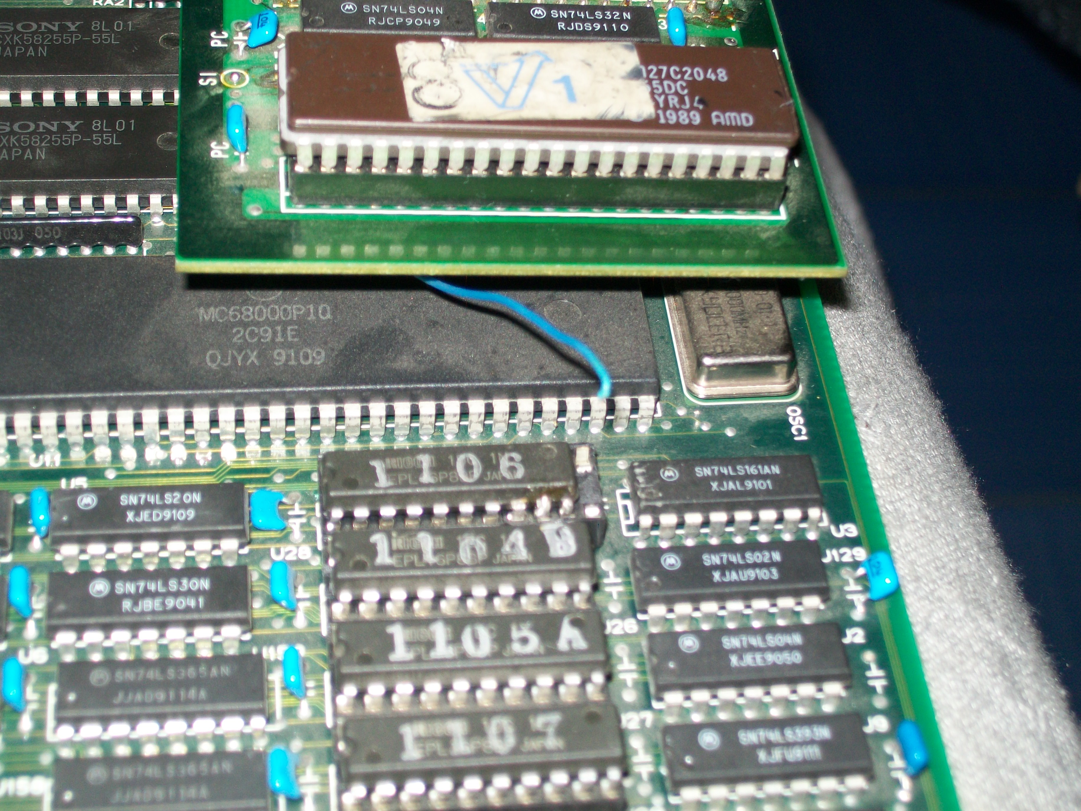
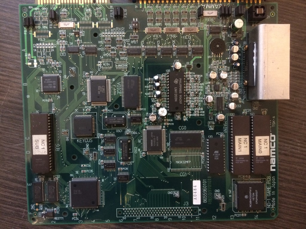
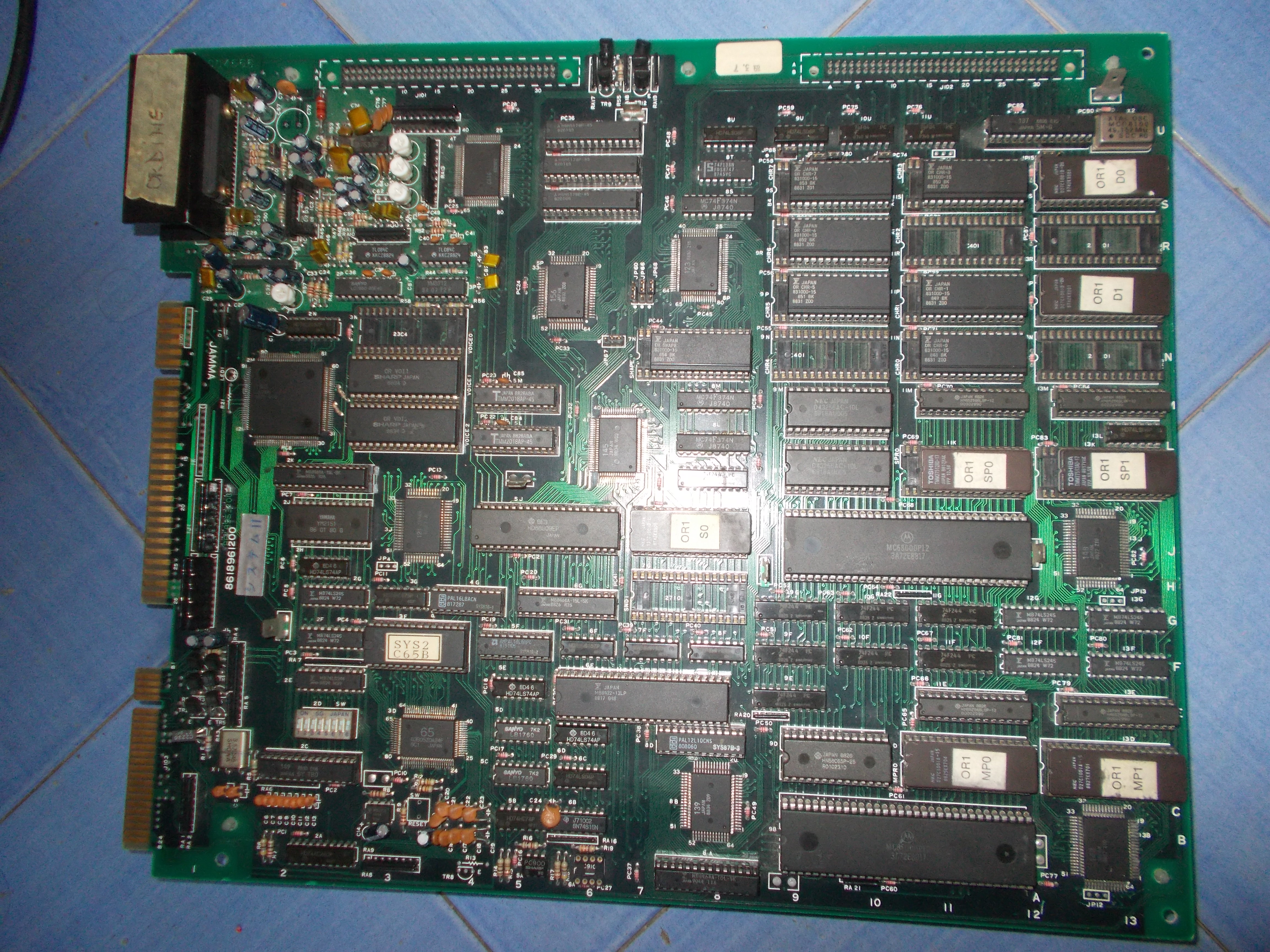
I received some days ago an Ordyne PCB for repair.Game runs on a powerful system called “Namco System 2” made of a CPU board:
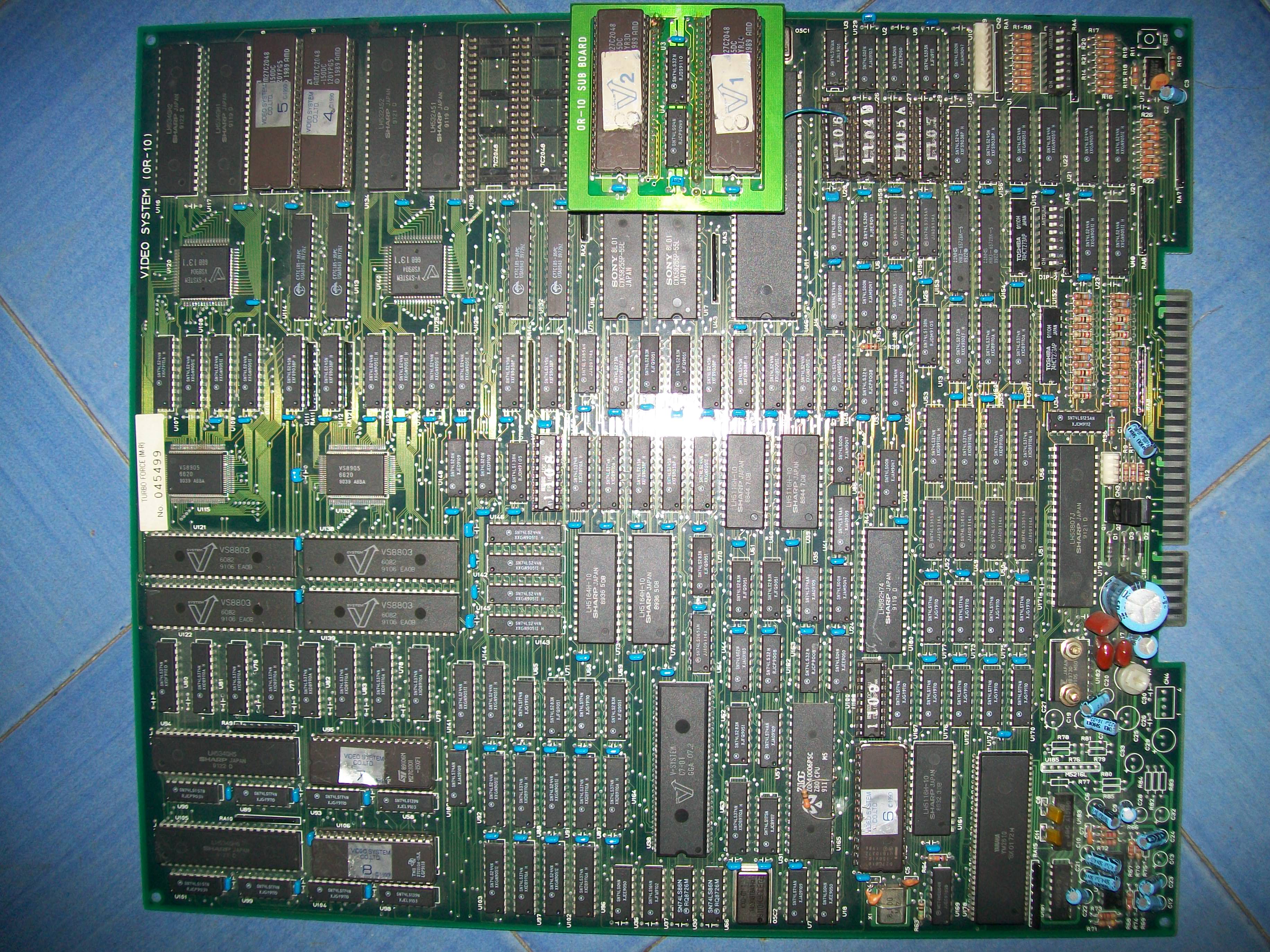
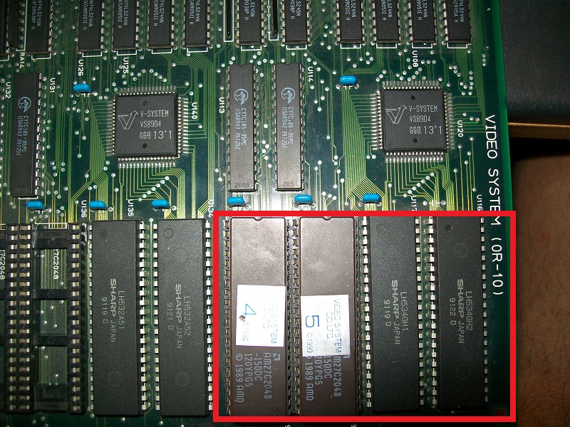
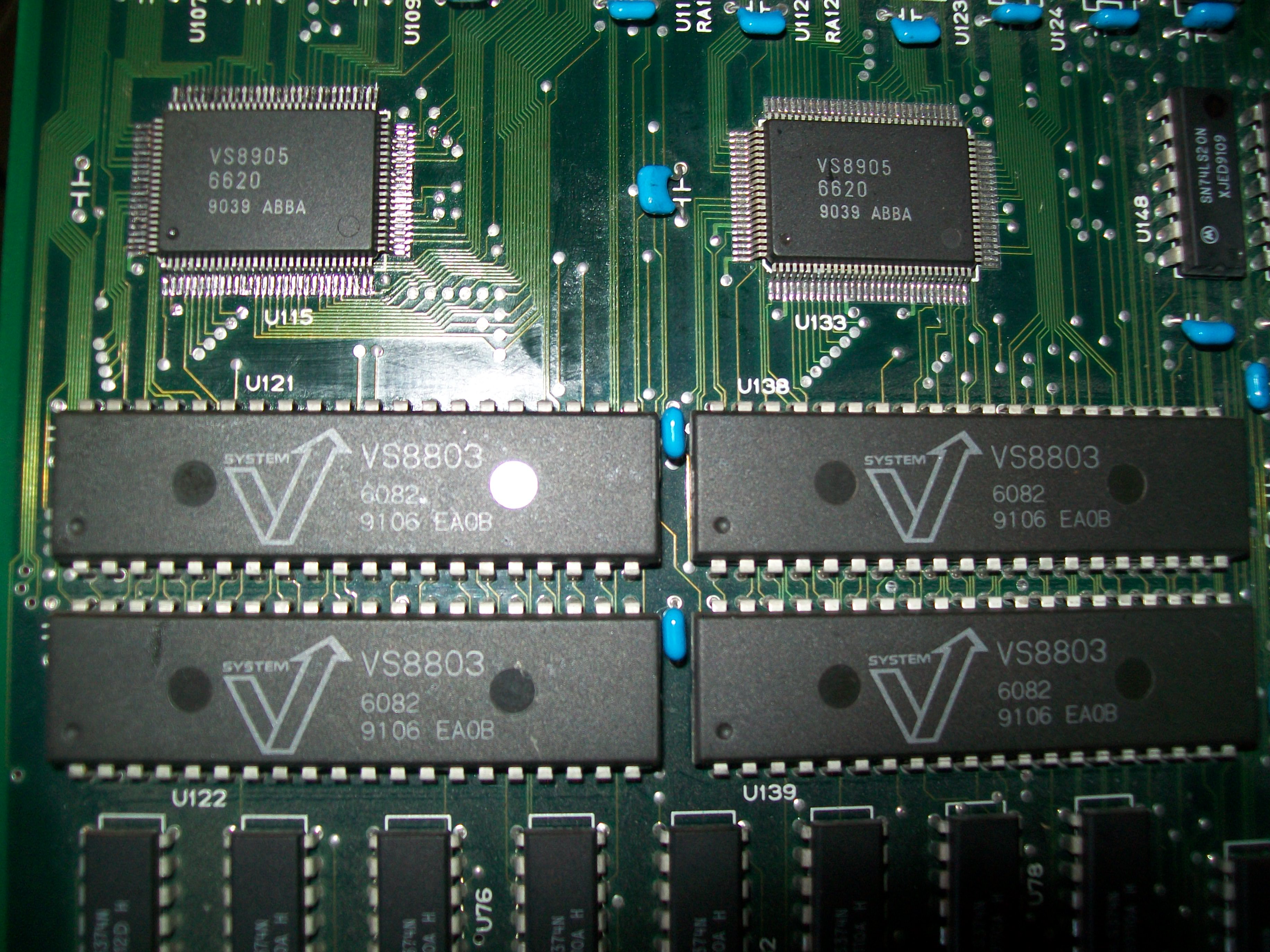
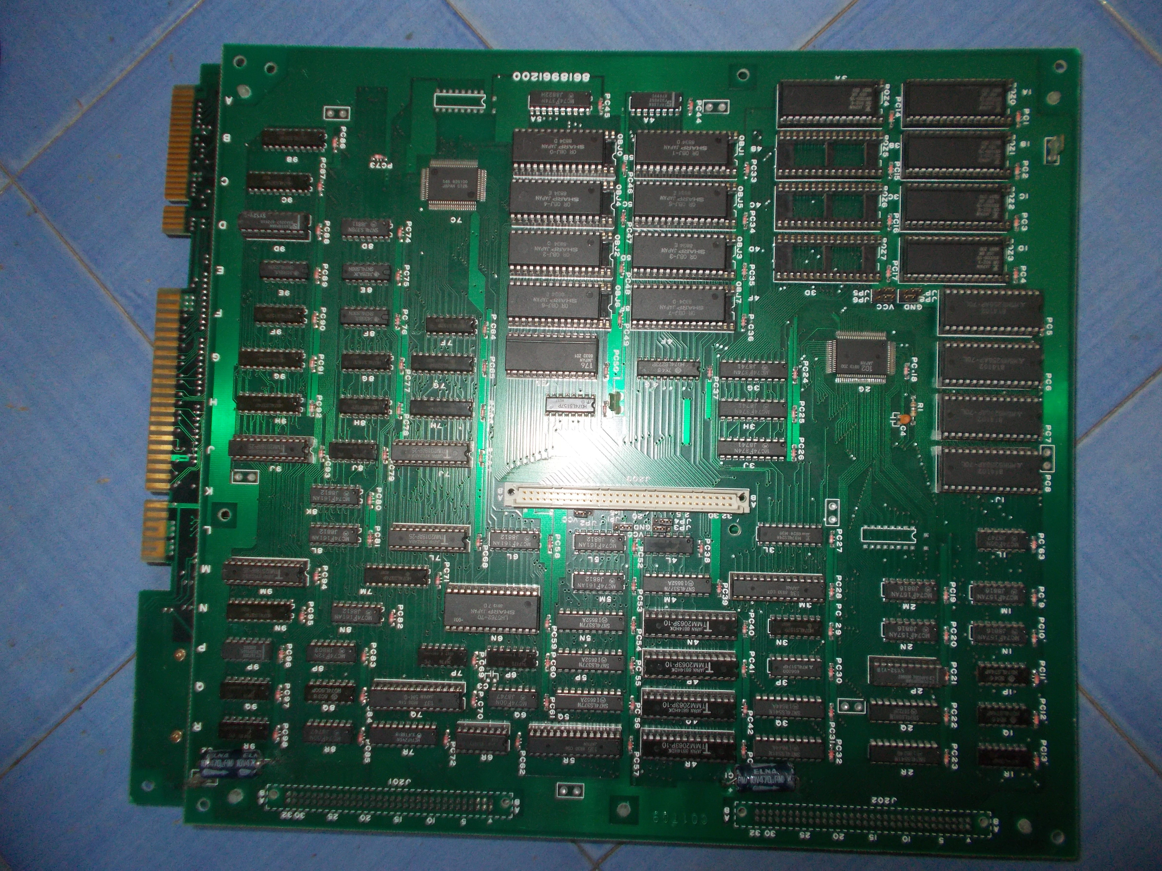
and a VIDEO board:

Here are some specs:

  • Main CPU: Motorola 68000 @ 12.288 MHz (16/32-bit instructions @ 2.1504 MIPS )
  • Sub-CPU: Motorola 68000 @ 12.288 MHz (16/32-bit instructions @ 2.1504 MIPS)
  • Sound CPU: Motorola M6809 @ 2.048 MHz (8-bit instructions @ 0.86016 MIPS)
  • MCU:
    • Hitachi HD63705 @ 2.048 MHz (8-bit instructions @ 2.048 MIPS)
    • Namco C68 (Mitsubishi M37450) @ 8.192 MHz (8-bit instructions @ 1.024 MIPS)

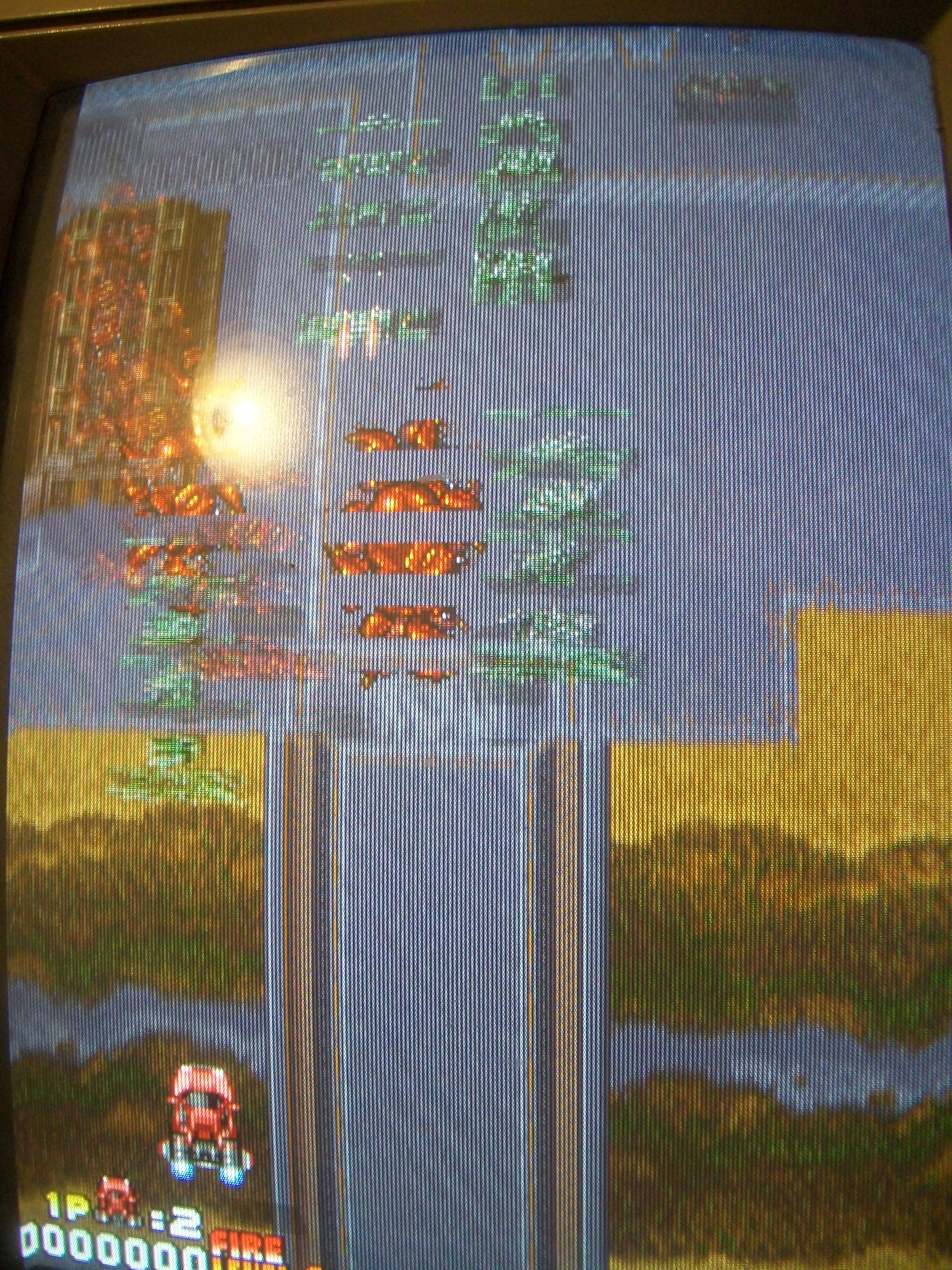
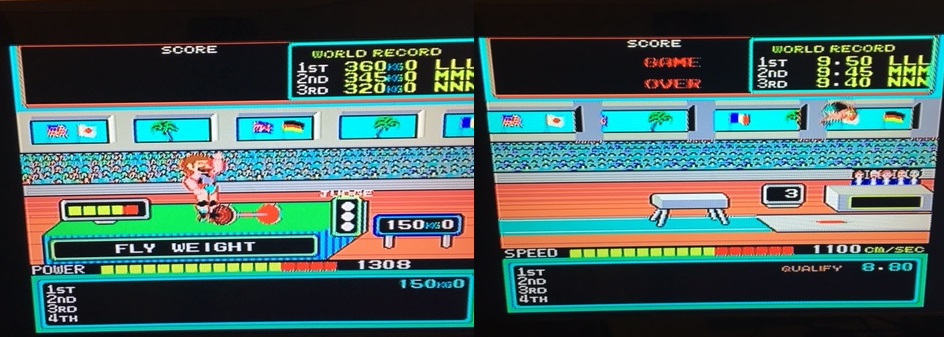
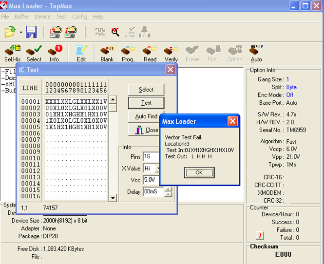
My board was faulty since it was sitting after performing the SELF-TEST without reporting any error  :

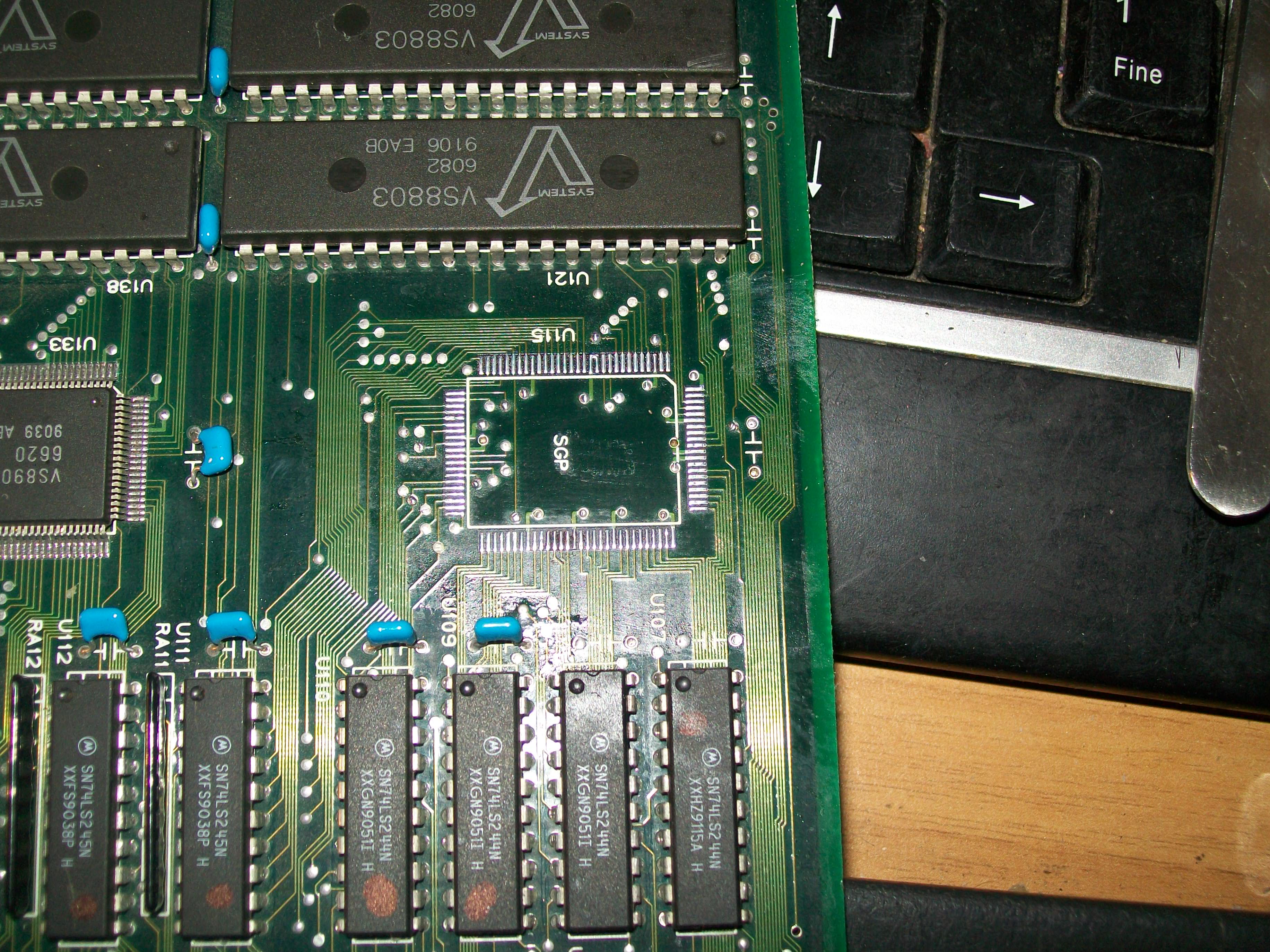
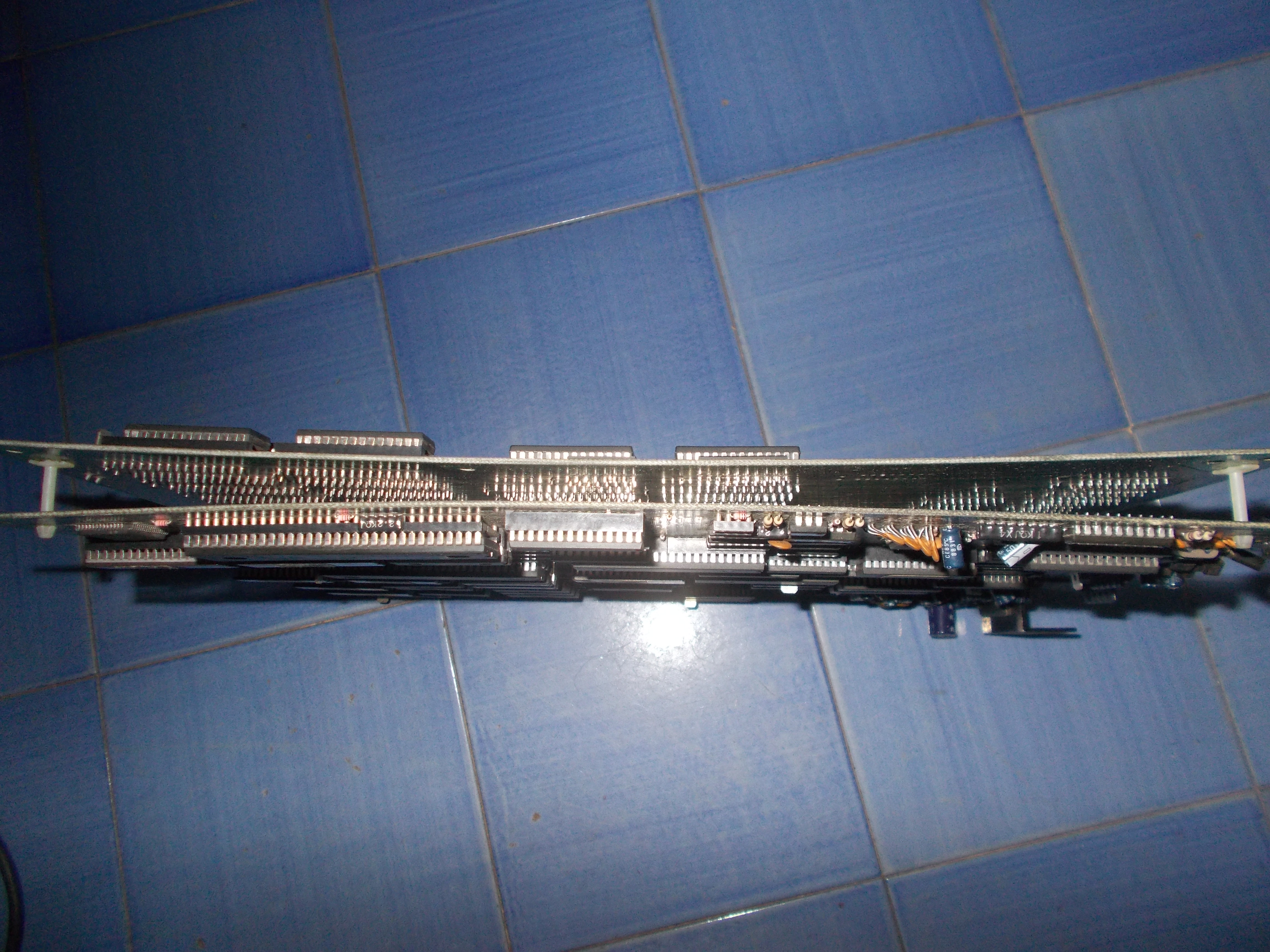
First of all I swapped a good motherboard but this didn’t lead to any improvement so the fault was located on VIDEO board.At a closer inspection I found some scratches on solderside of this board:

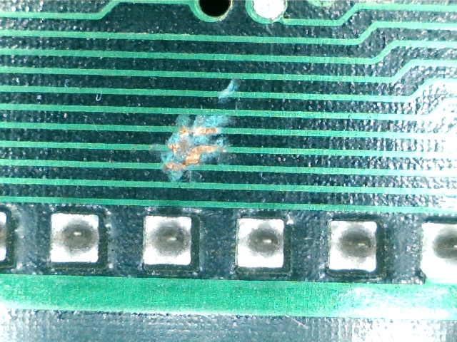
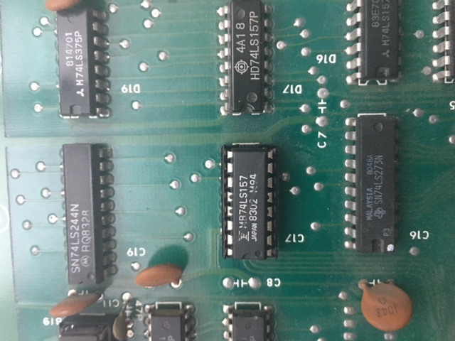
One trace was really severed, it was the one connected to pin 9 of the KEY custom ‘176’.Problem was caused due the board has been crushed under some weight hence solder sides of the two boards were touching and scratching each other:

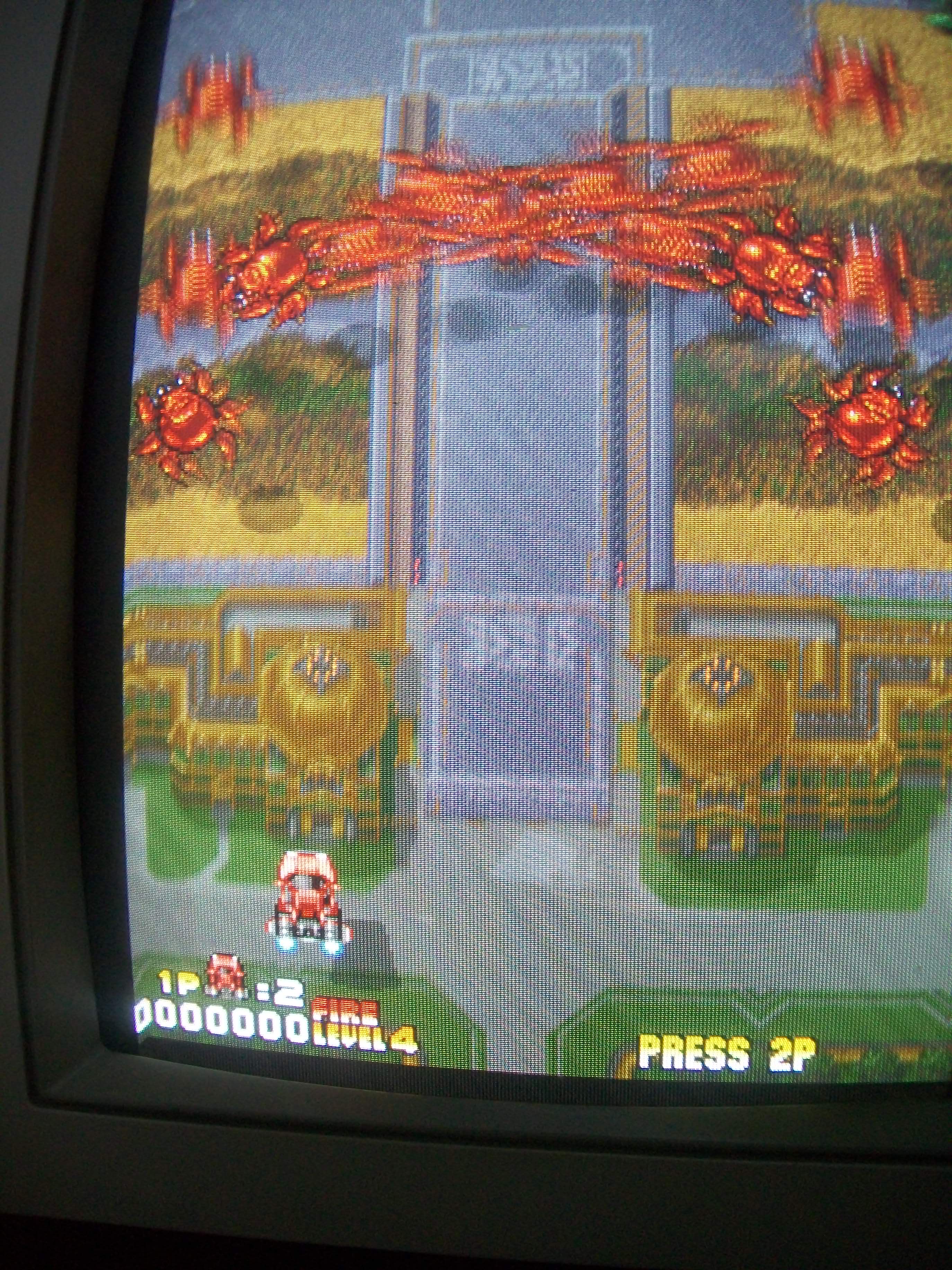
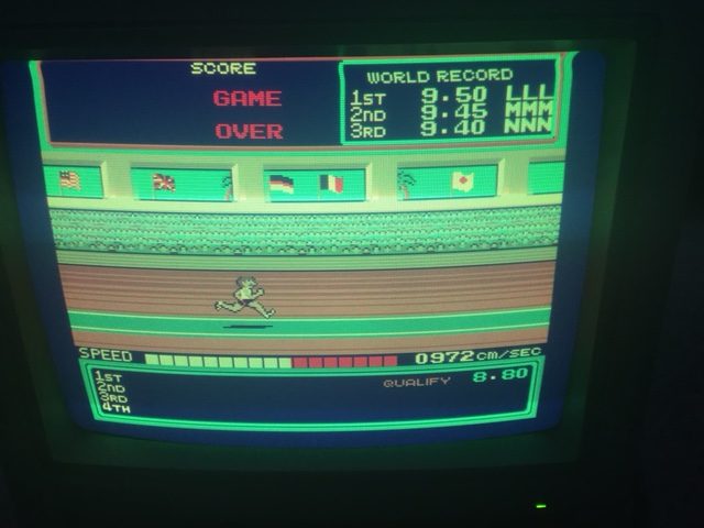
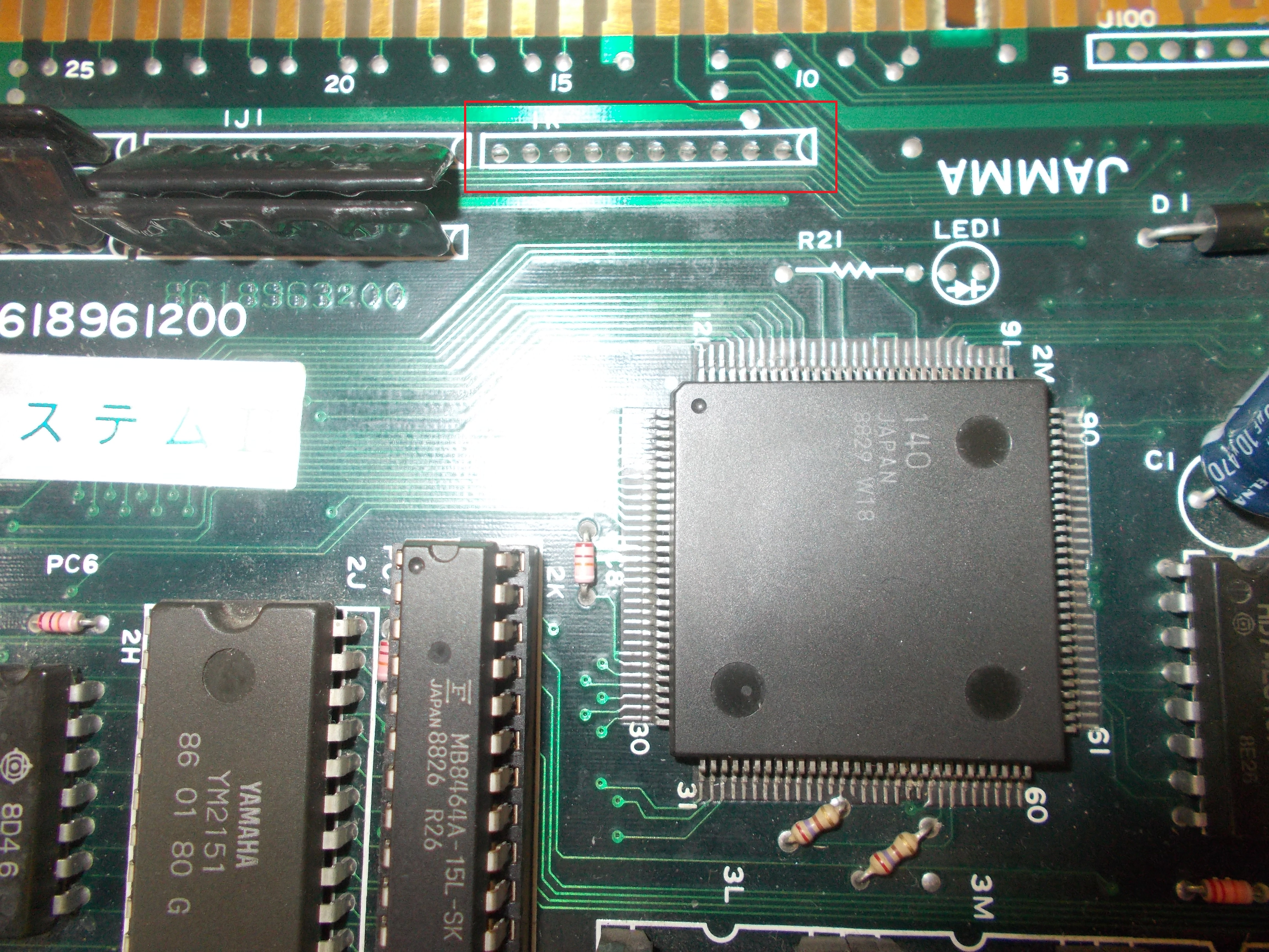
After patched the trace, the board successfully entered in game but I could not coin up.I quickly pinpointed this fault to a missing ‘CUS95’ resistor array @1K near the JAMMA edge:

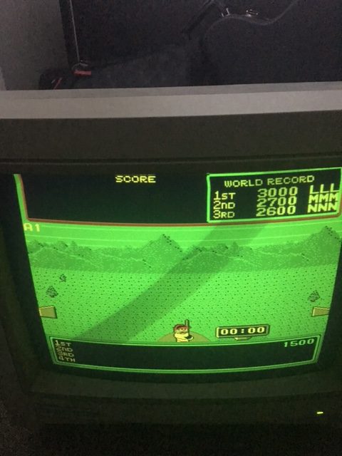
No further issues were found so board 100% fixed.

 Posted by at 6:40 pm

Moon Cresta (Nichibutsu) repair log

 PCB Repair Logs  Comments Off on Moon Cresta (Nichibutsu) repair log
Jul 162017
 

Received this original Moon Cresta PCB (board ‘SMC-2FJ’ manufactured by Nichibutsu) for repair :

Board booted up but some sprites were upside down and partially doubled :

Some Fujitsu TTLs were present so I went through them with my logic comparator.I quickly found a suspicious 74LS08 @6H:

It was really bad once tested out of circuit:

Now sprites were correctly placed but I noticed that the bullets were missing:

Looking at schematics there are two separate circuitries which generate yellow and white bullets.Probing them I found that the two active LOW signals /YBPS and /WBPS were stuck HIGH all the time also when you pressed the fire button and generated the bullets:


The signals are geneated by a 74LS139 @4C:

My logic comparator complained about pin 11 everytime I pressed the fire button and hence activated the selection line B on pin 13:

I pulled the TTL and I had confirm it was bad in that specific gate:

Fitted a good TTL and bullets were displayed again.Board 100% fixed.

 Posted by at 10:49 am

Turbo Force repair log #1

 PCB Repair Logs  Comments Off on Turbo Force repair log #1
Jul 092017
 

Got this faulty Turbo Force PCB for repair:


First of all I soldered back an hanging wire:

Then I powered the board up : the fault concerned some sprites, they were scrambled:

The relevant data are stored in four devices :

Probing them revelead that some address line had abnormal activity (good on left of the below picture)

Address lines for the sprites devices are generated by one of the two surface mounted custom ‘VS8905’ (the one @U115)

I played the card of replacing it :

And this was successful, board fixed.

 Posted by at 7:28 pm
Jul 092017
 

In this log I fix the sprite’s incorrect colors as discovered in part 1. To review the problem see the image below. Note that the colors for the weightlifter are incorrect, the runner also has red shadow instead of black and the colors for the area in between the flags on the right are also incorrect.


Initially, I thought the area between the flags were actually made up of background tiles. These are actually sprite objects used as background graphics. I used my test rom to confirm this.


The bipolar proms I ordered finally came but were all faulty! So that was a complete waste of time and money. The good news is after checking the palette prom [ several times over ] it appears to be good and I must have been reading it incorrectly with my TopMax in part 1 of the repair log.

I thought about this for awhile and had an idea that would help me troubleshoot. Firstly, I looked at the color palette for Hypersports in MAME and took down some notes.


After comparing the colors of the sprites from images online [ google images was a good starting point ] with colors from the table above, my suspicions were that there was a stuck bit somewhere. Black [ color 0 ] is being displayed instead white [ color 1 ].

For black [ color 0 ] to be displayed instead of white, bit 0 would have to be stuck low. Color 2 is also being shown instead of color 3 and the only way this could happen is if bit 0 was stuck low. The athlete’s shadow is also being shown as red instead of black for the same reason which results in color 8 being shown instead of color 9.


The backgrounds and sprite data appear to be combined at the LS157 at A4 which then form the signals OUT0-OUT4 at the LS174 A2. These 5 signals represent the color of a single pixel on the screen [ 32 possible colours ]. But I’m more interested in the signals OCOL0-OCOL3 [ object/sprite colors ] so I begin poking around at the inputs and outputs of the LS157 at C17 first. I generally choose the multiplexers to troubleshoot first whenever it’s relevant because these seem to get worked fairly hard [ especially in the video circuit ] and exhibit higher failure rates in these areas.


Pin 4 [ 1Y ] output of C17 appears to be stuck low, exactly what I was looking for. This was later confirmed after testing the chip out of circuit.


The Fujitsu in C17 is a temporary measure, I promise. It’s a working pull from my Gyruss and I didn’t have any other spares on hand.


The colors seem right although I seem to be missing overall color from the CRT.


Changing it over to my LCD just to confirm that my 1084 probably needs an adjustment of some sort.


Jul 012017
 

These system boards from Namco has a common problem: SMD capacitors

These caps expecially the ones produced in the 90s are very unreliable and sooner or later will start to leak

On my boards there isn’t one that has the ESR in a good range.

On Namco system NA ( Emeraldia, Tinkle Pit, Super World Court) or NB ( Point Blank, Nebulas Ray), the problems you will face are sound related ( low sound or scratchy ), on ND system ( Namco Classic Collections), the SMD caps are used also for the RGB amplifier and in addition you will get colour problems.

I will take as an example a Namco Classic Collection I just finished to repair and which had all the problems coming in about one week of intensive use after a while in storage.


First of all it started to have trails on the RED component of the image.

The system uses a common RGB amplier LM1203 which for example is used on the majority monitors neckboards

Here are the usual circuit taken from the schematics of the LM1203:

As you can see , on the inputs of each colour component you have to place a 10uF cap.

Namco engineers decided to use a 4,7uF but I tested and there are no differences between the two values.

So, if you have colour quality problems on your Namco Classics Collection pcbs, first thing is to recap the RGB input section using commercial

electrolitic caps.


I am not a fan of brute force recap, so with my ESR meter I usually check all the caps and change only the ones that have a very out of range value.

As said before, after few days I get no sound for a while and after about 5 minutes, you could hear it coming up but very scratchy.

The amplifier got also really hot after a short time.

The system uses a LA4705 sound amplifier


I probed with the ESR meter all the caps and found out the both the small ones 2,2uF placed on  IN1 and IN2 had a value of more than 99 ohms.

The other ones also were really not in the specification range but to get sound back it was enough to change the small ones.


As said the sound section of Namco system NA and NB is the same more or less, therefore if you start to have low sound and you don’t have an ESR meter,

change the 2,2uF, 47uF (33uF on the amp schematics) and 100uF one.