ReproductionsComments Off on Konami ‘501’ reproduction
Apr282019
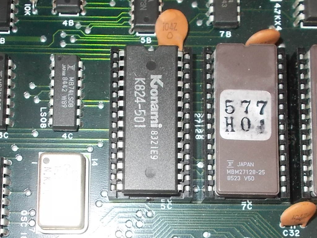
The Konami ‘501’ is one of the many custom ICs you probaby encountered when dealing with PCBs from this manufacturer.Most of times the chip (28 pin 600 mil DIP package) comes with scratched-off part name, sometimes not like on my Rush’n Attack PCB:
It can be found on not so many PCBs like shown on this useful spreadsheet (credits to ‘mattosborn’ on KLOV forums)
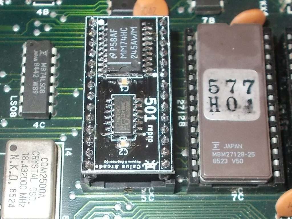
Actually there is already a reproduction of it which uses the ColinD CPLD 28 pin board (based on Altera EPM7064S) of which ‘Porchy’ wrote the code (available here for download).I simply made what I call a ‘poor man’s’ version using simple surface mounted TTLs gates:
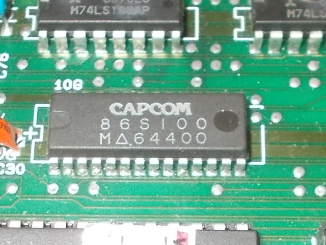
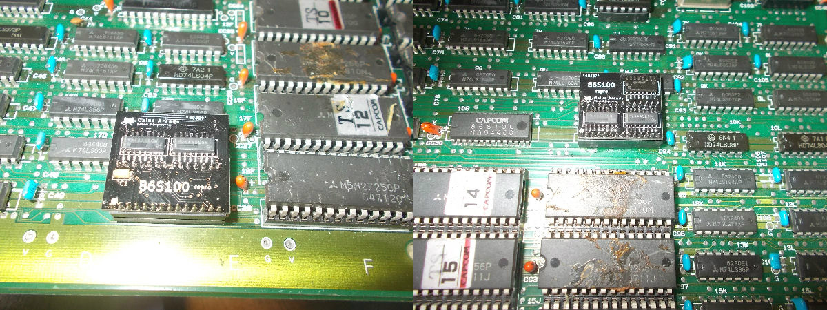
Code name : ’86S100′.Nothing really ‘TOP SECRET ‘, just a little custom IC you can find on many Capcom arcade PCBs from pre-CPS1 era.To name few :
1943
Bionic Commando
Black Tiger/Black Dragon
Mad Gear
Rush & Crash/The Speed Rumbler
Side Arms
Street Fighter
The chip is a 28 pin one with plastic package and pitch of 1.778mm :
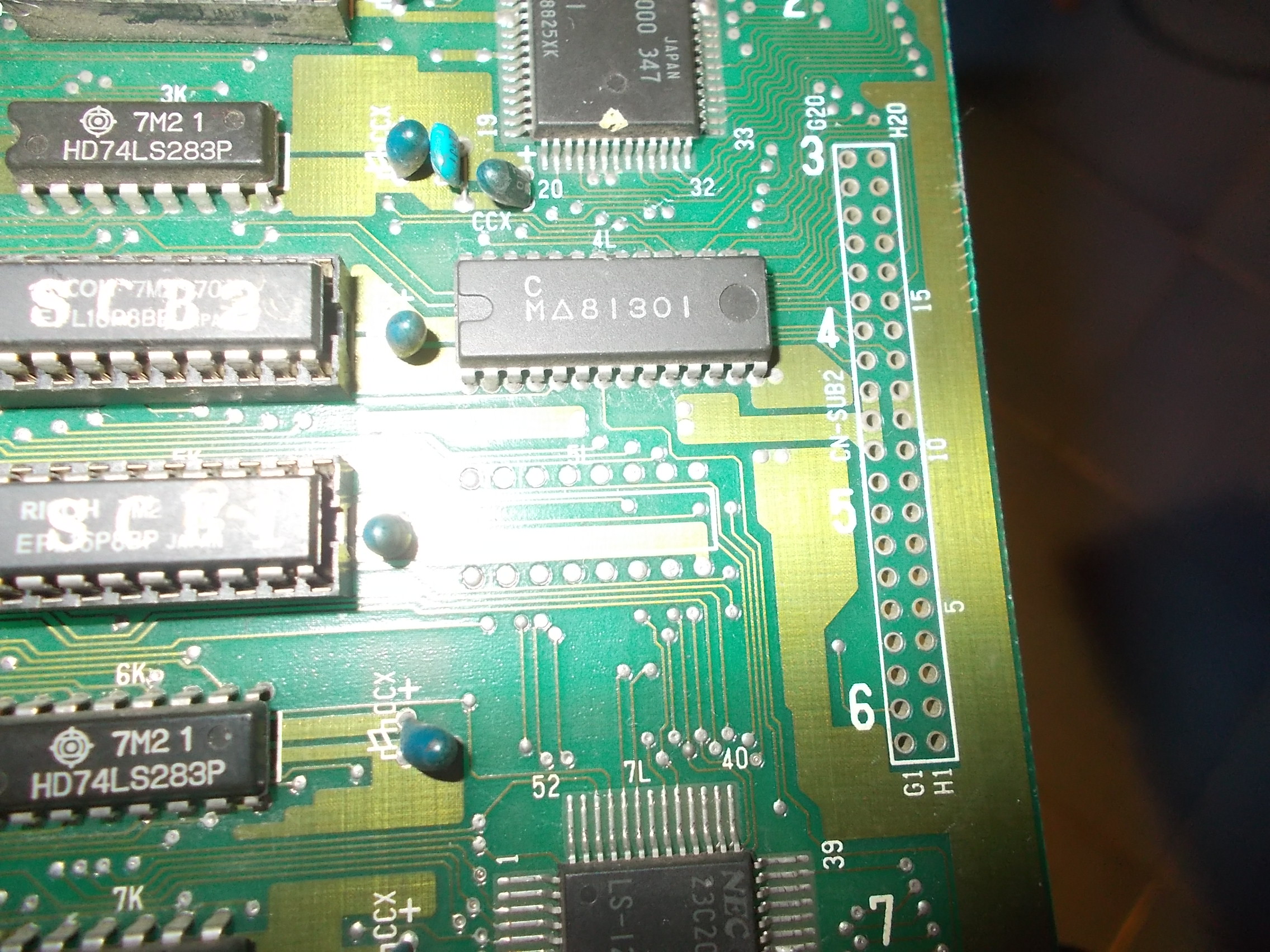
Sometimes you can find it under different part name but same functions, like on a Mad Gear PCB :
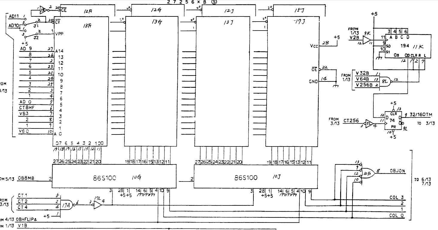
This custom IC is involved in graphics generation being directly connected to data bus of the GFX ROMs as shown on Bionic Commando schematics:
Being a not really reliable part (sometimes you can find it literally ‘fried’) and quite hard to obtain as spare I decided to give a try to reproduce it.As usual I looked at how bootlegers re-engineered it and how the custom functions were implemented in earlier Capcom hardware.I succeeded in my purpose it but I actually had to make two versions of it because the original ’86S100′ can work in two modes depending on the logical state of its pin 1 (if hard-wired to GND or VCC).
Here’s final testing of both reproductions on a Bionic Commando and 1943 PCBs:
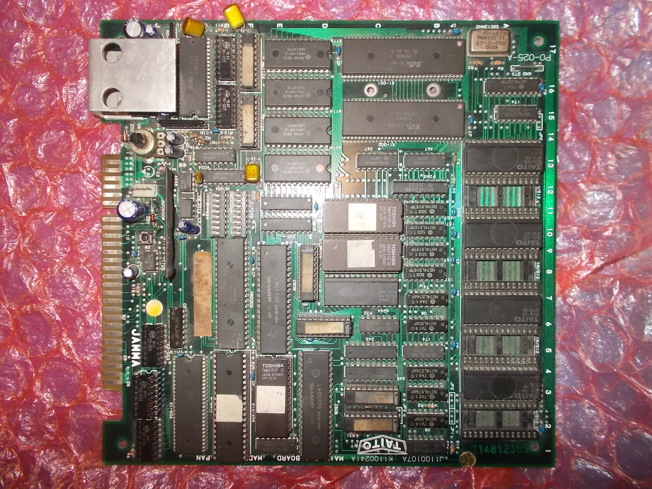
Some time ago I bought a lot of original faulty boards, there was among them a Taito PCB which at first gance I could not identify:
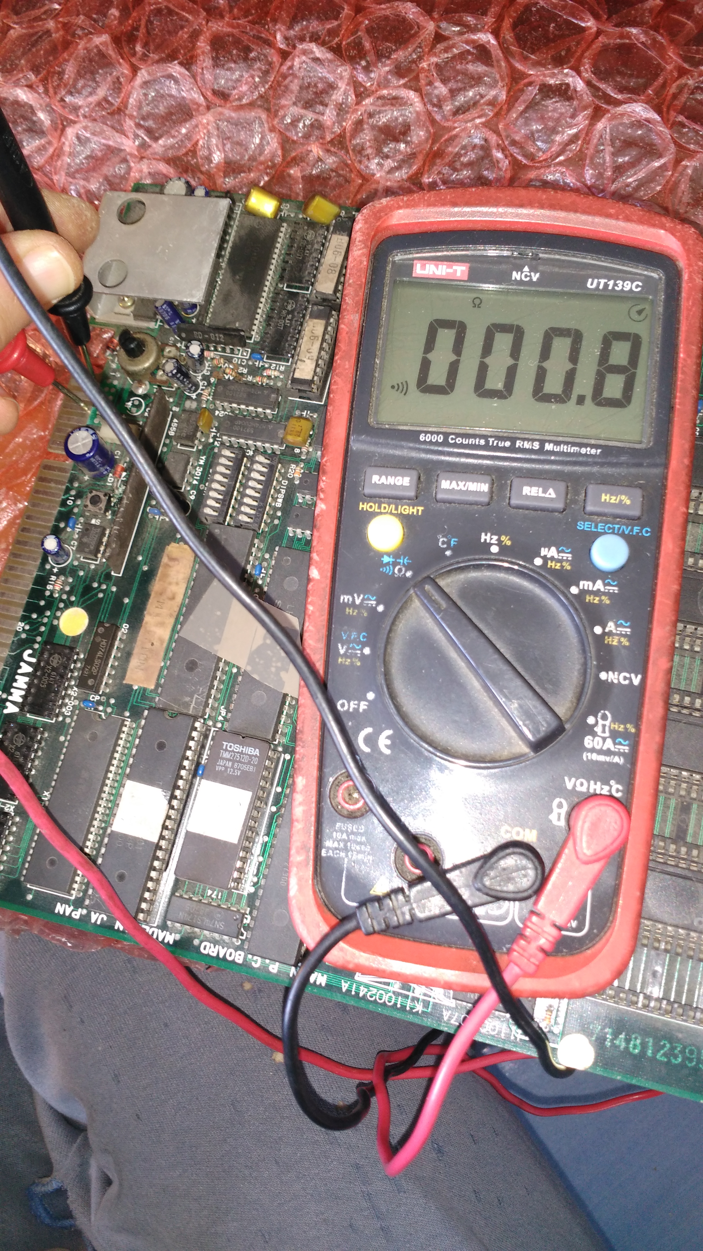
I could not power it up because there was a dead short between GROUND and +5V :
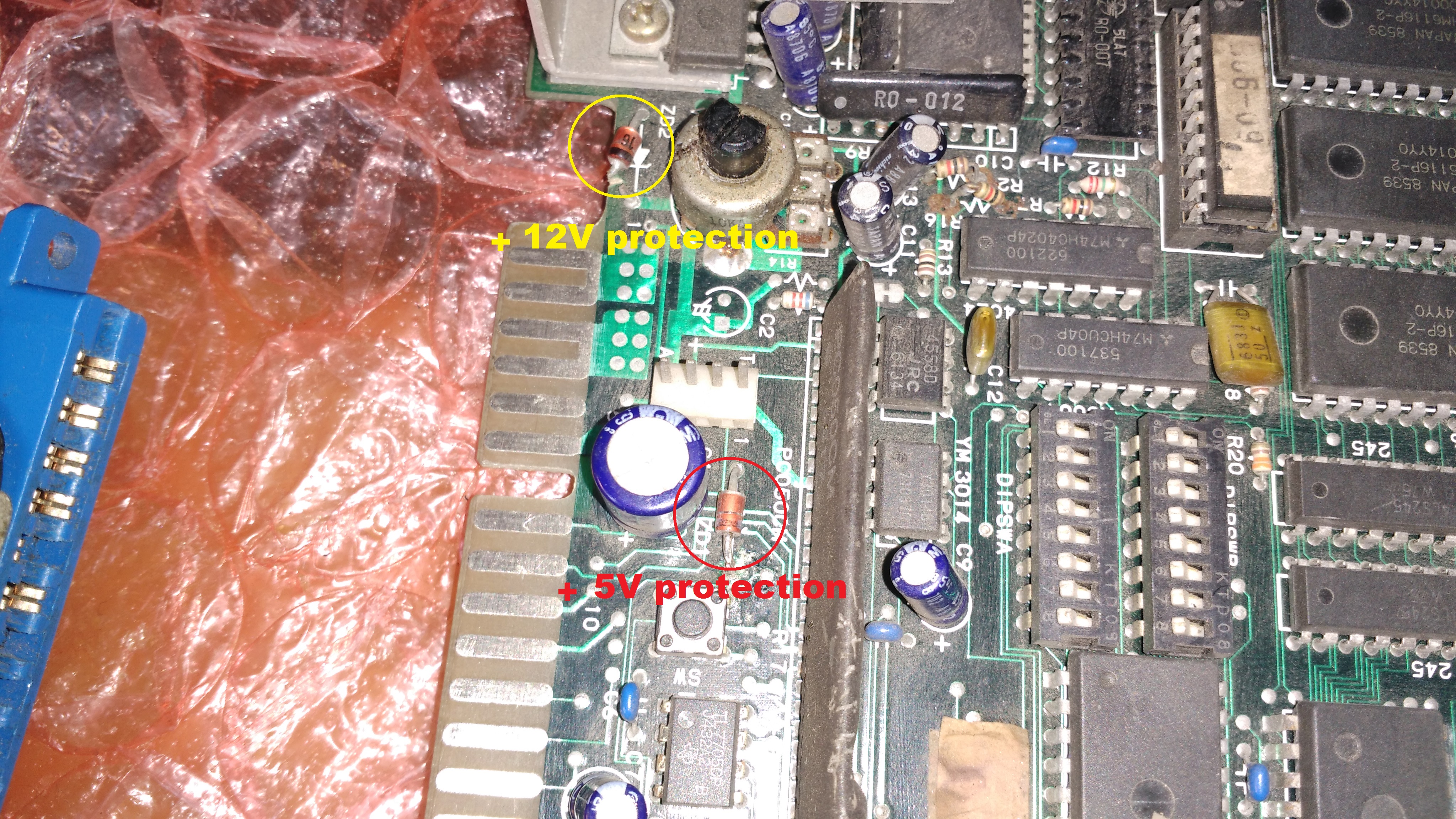
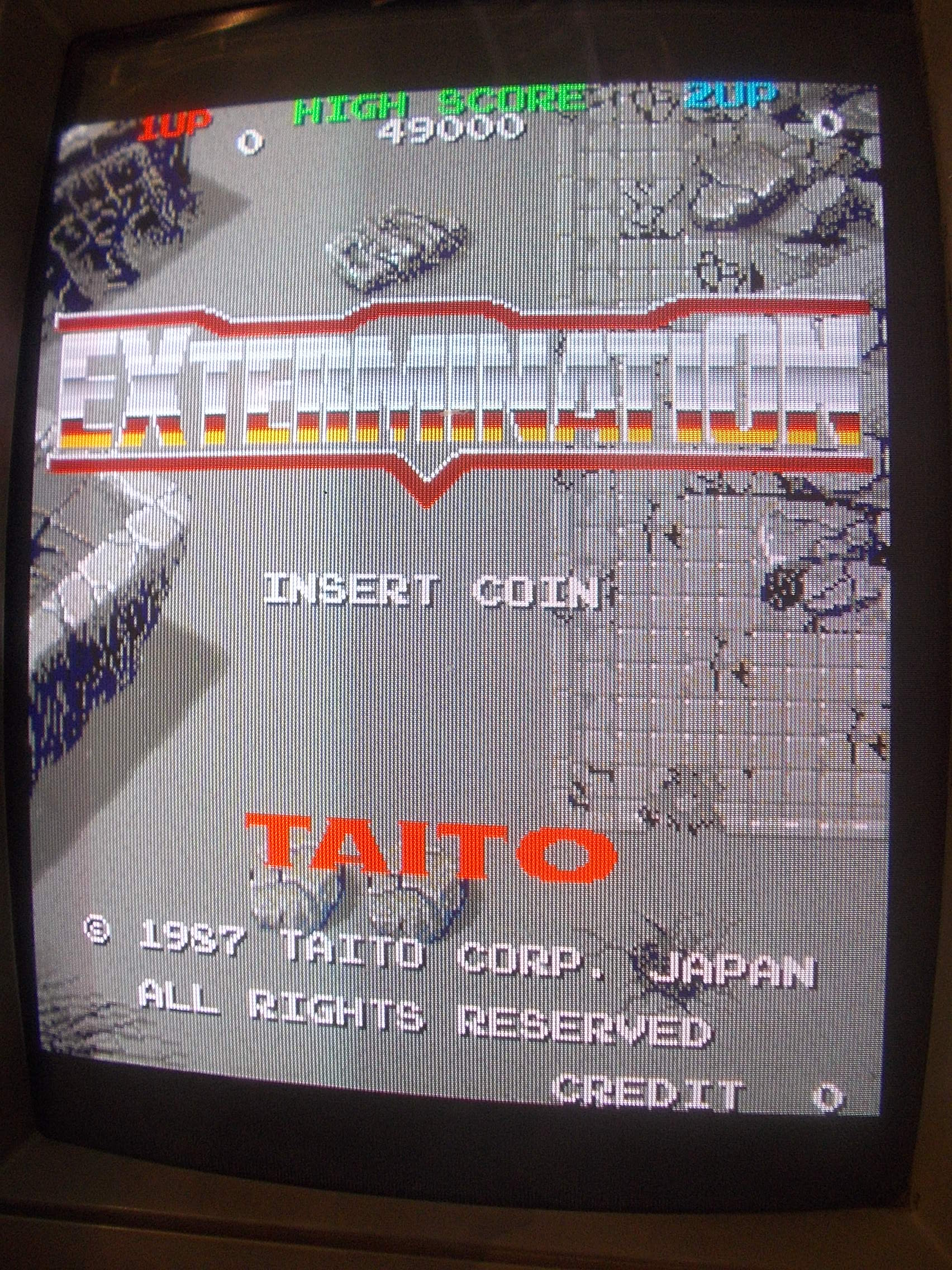
So I dumped some ROMs and it turned out to be Extermination, a vertical shoot’em up game (that runs on “The New Zealand Story” hardware) released by Taito in 1987.Someone previously tried to troubleshoot the board and cut one terminal of a zener diode thinking it was shorted but this was for +12V line protection whereas there is another zener diode to protect +5V which was actually bad causing the short to GROUND:
Once replaced the zener diode and cleared the short I powered the board up and it booted into game but sound was missing and colors were wrong with a dominant blue :
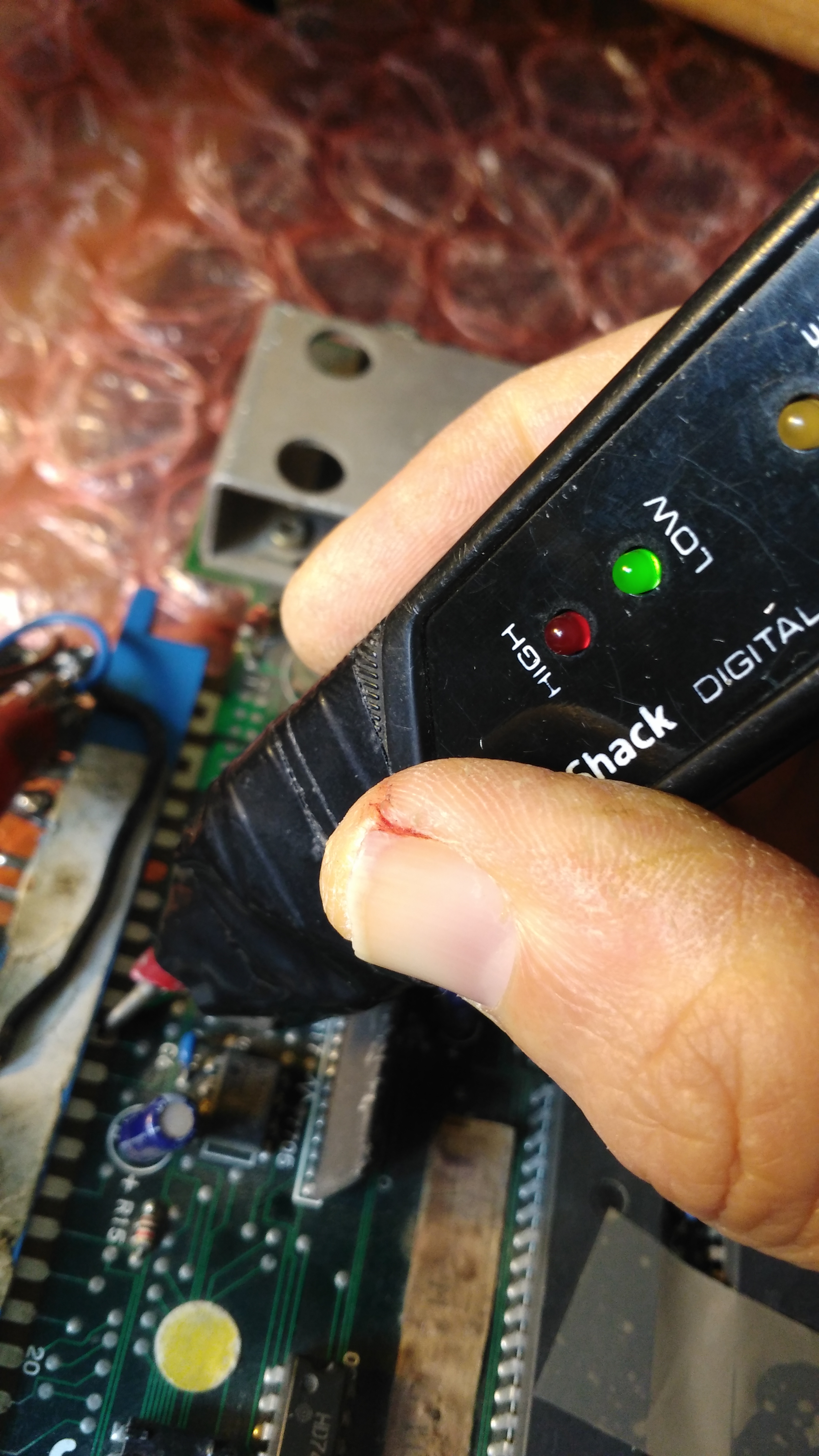
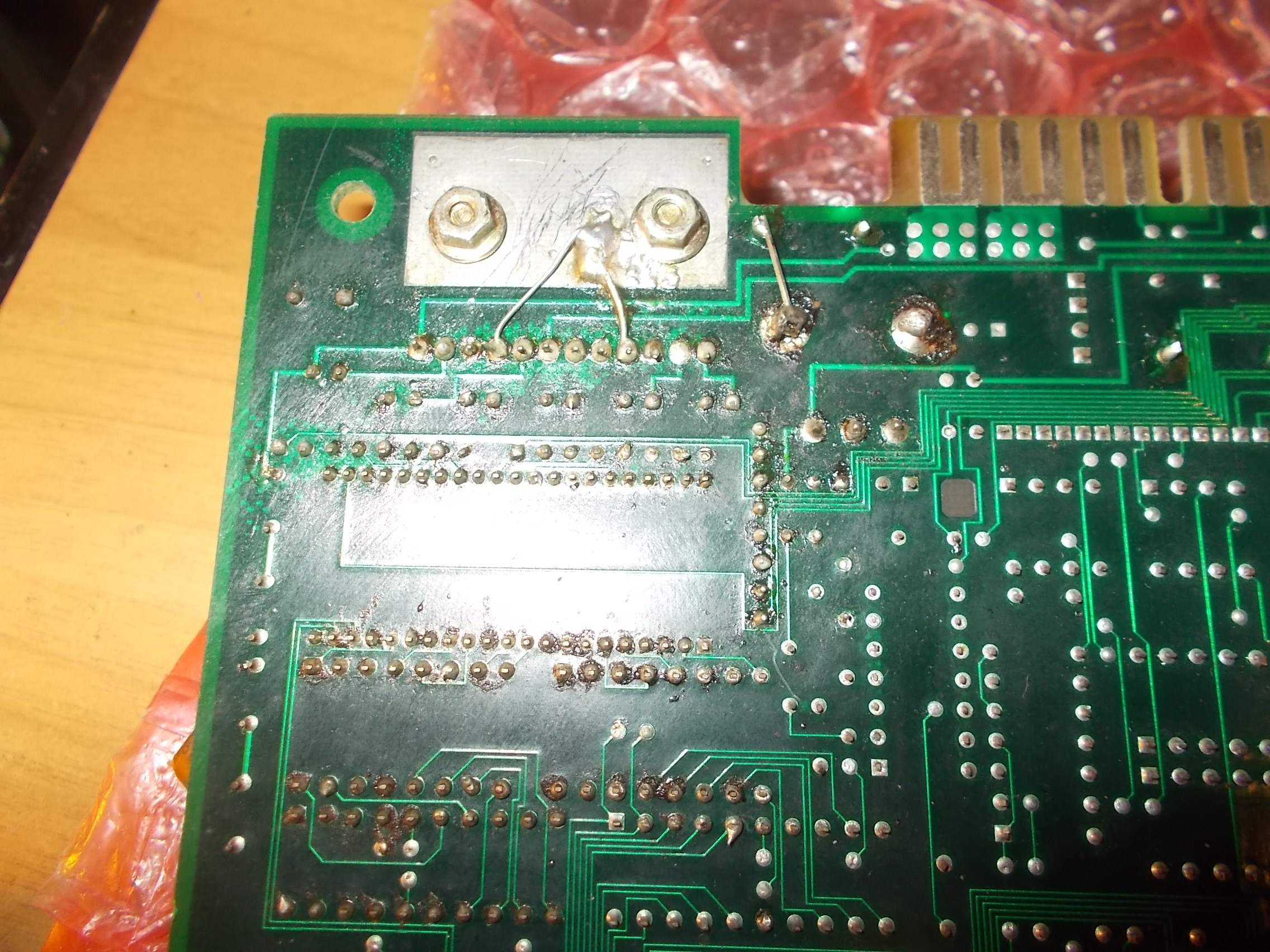
A blueish image means the RED color is missing or has some troubles.This was confirmed by the logic probe, the signal was indeed stuck low :
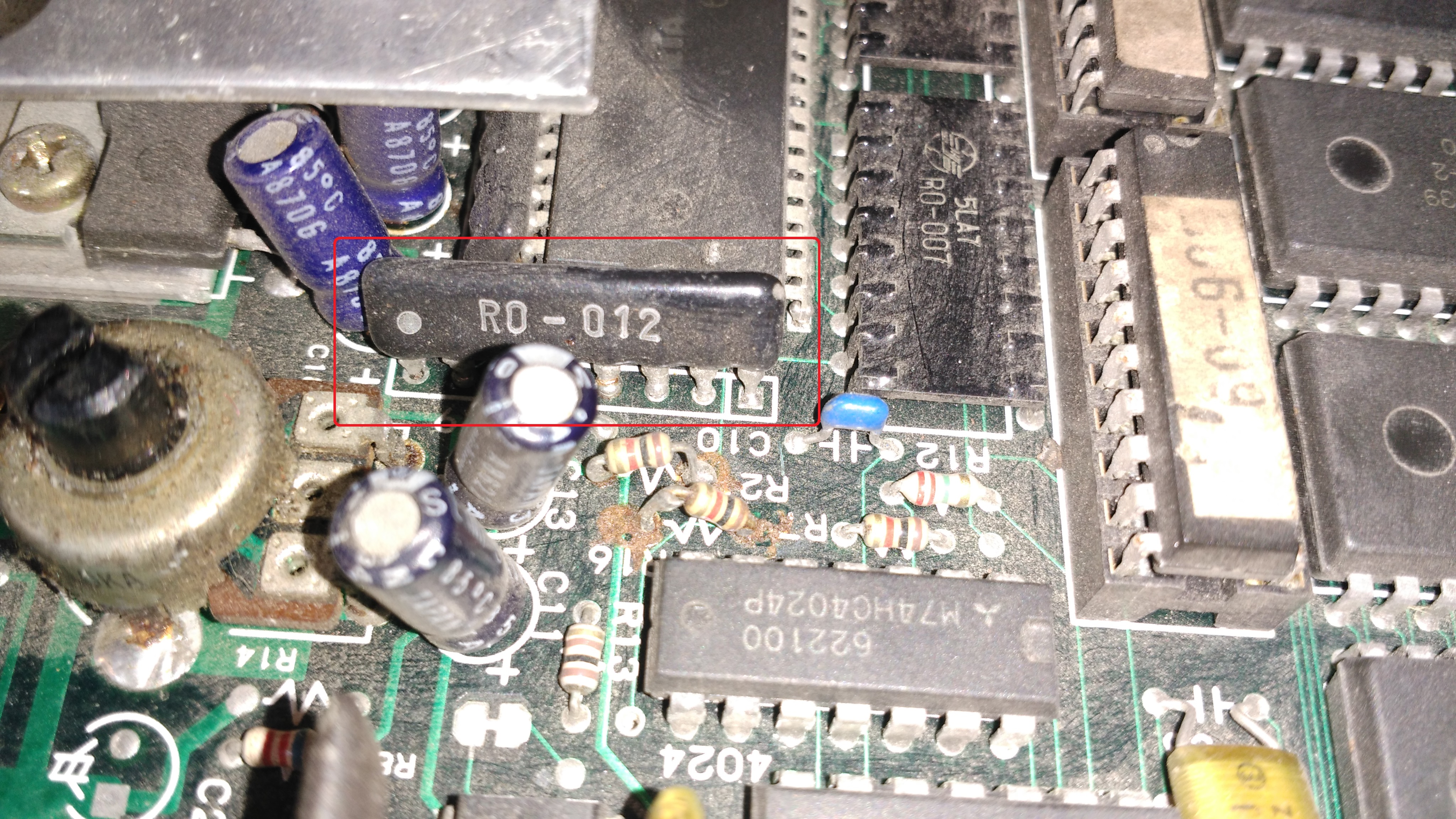
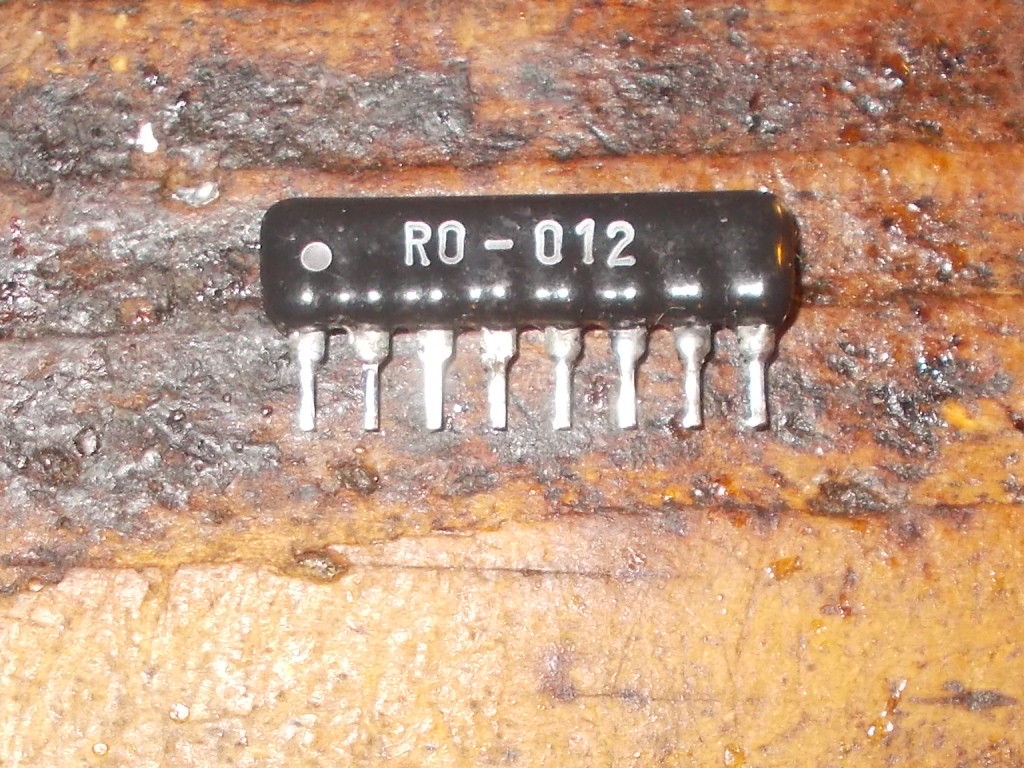
I could trace the JAMMA edge connector pin of RED back to a SIL component marked ‘RO-012’, a typical R/2R resistor ladder used as RGB DAC (one for each color).A closer inspection revealed the part was mounted backwards:
Reinstalling it with right orientation restored the RED color but image was now purplish :
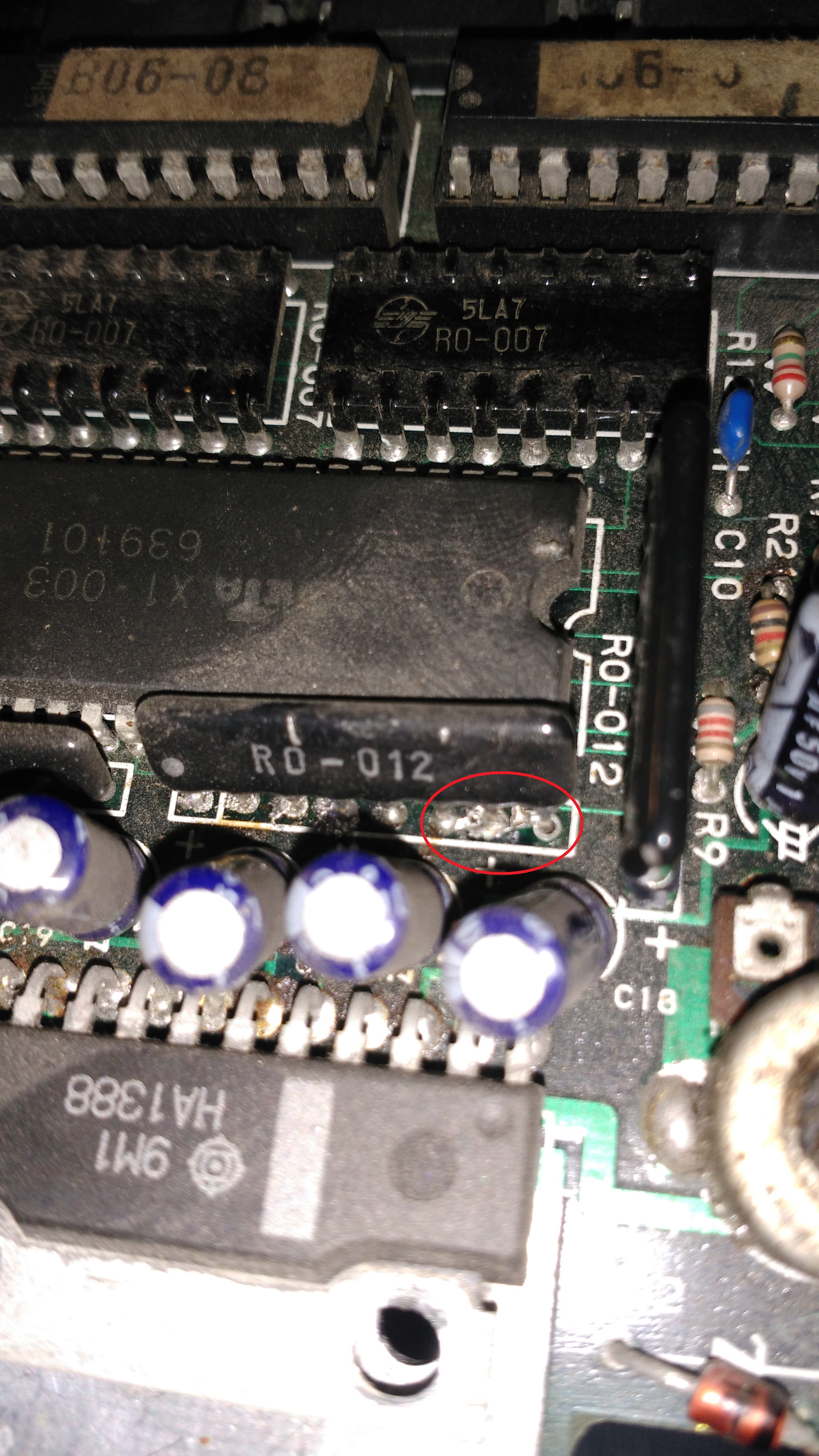
This meant the GREEN color had some troubles.I located the relevant ‘RO-012’ DAC near the sound amplifier and found that some pins were shorted by a solder bridge:
Removing the bridge finally restored the correct colors :
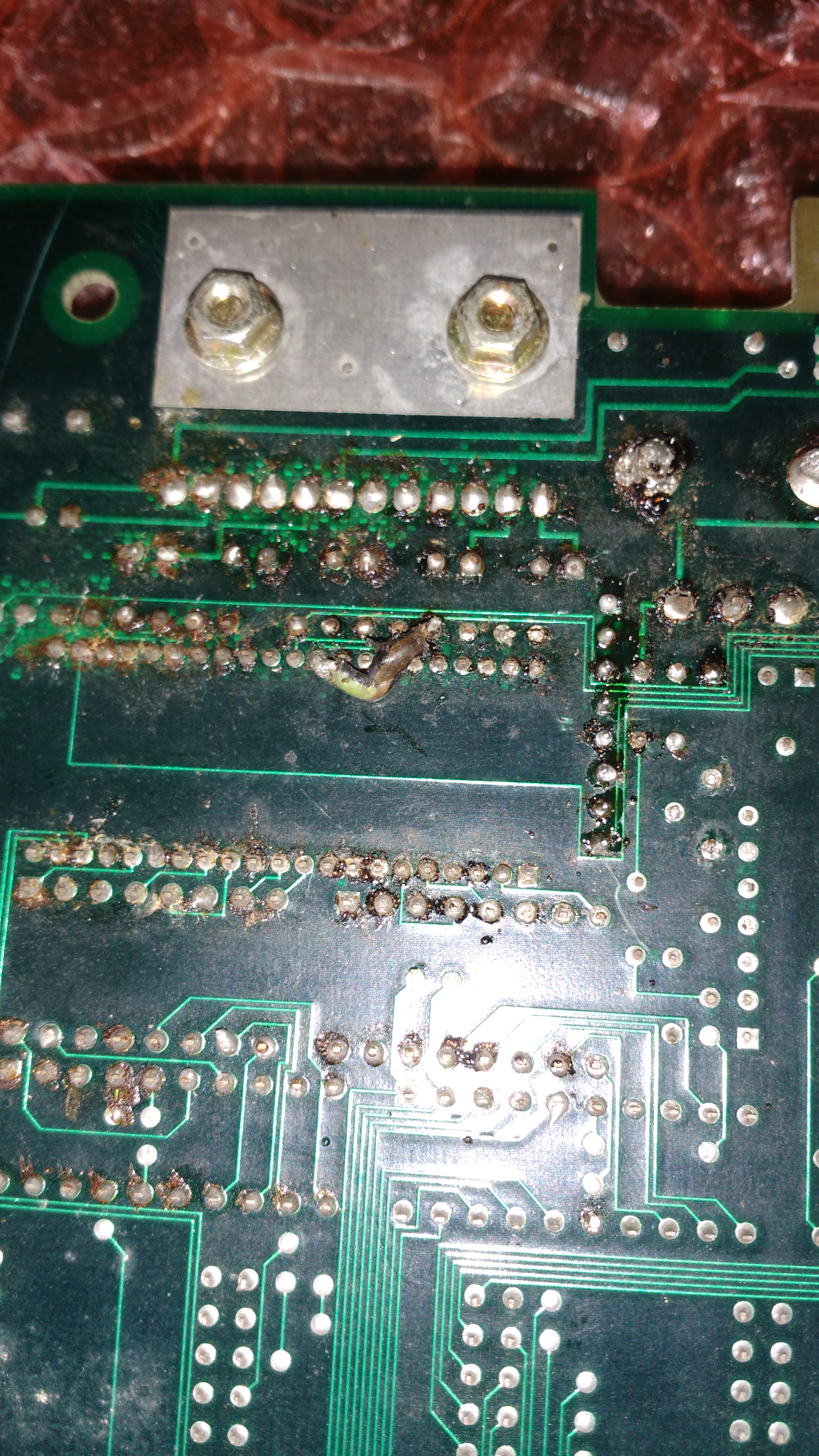
Now the lack of audio.From signs on solder side I noticed someone previously reworked the sound section replacing the amplifier (an Hitachi HA1388) and potentiometer (and perhaps also capacitors)
Checking the +12V confirmed this voltage was present on board but not on amplifier when I put the black probe of my multimeter on the two GROUND pins of the HA1388 (pin 4 and 9).At the end it turned out that who replaced the amplifier and potentiometer managed to lose their GROUND connection likely ripping off the rivets from the holes (power pins are always harder to desolder due to presence of internal planes).I restored the connections in this way :
Sound was back again.Board 100% fixed and job done.Before archiving this repair I took the chance to see if some parts (simple ones, not digital ASICs) were worth to be reproduced.I chose the aforementioned ‘RO-012’:
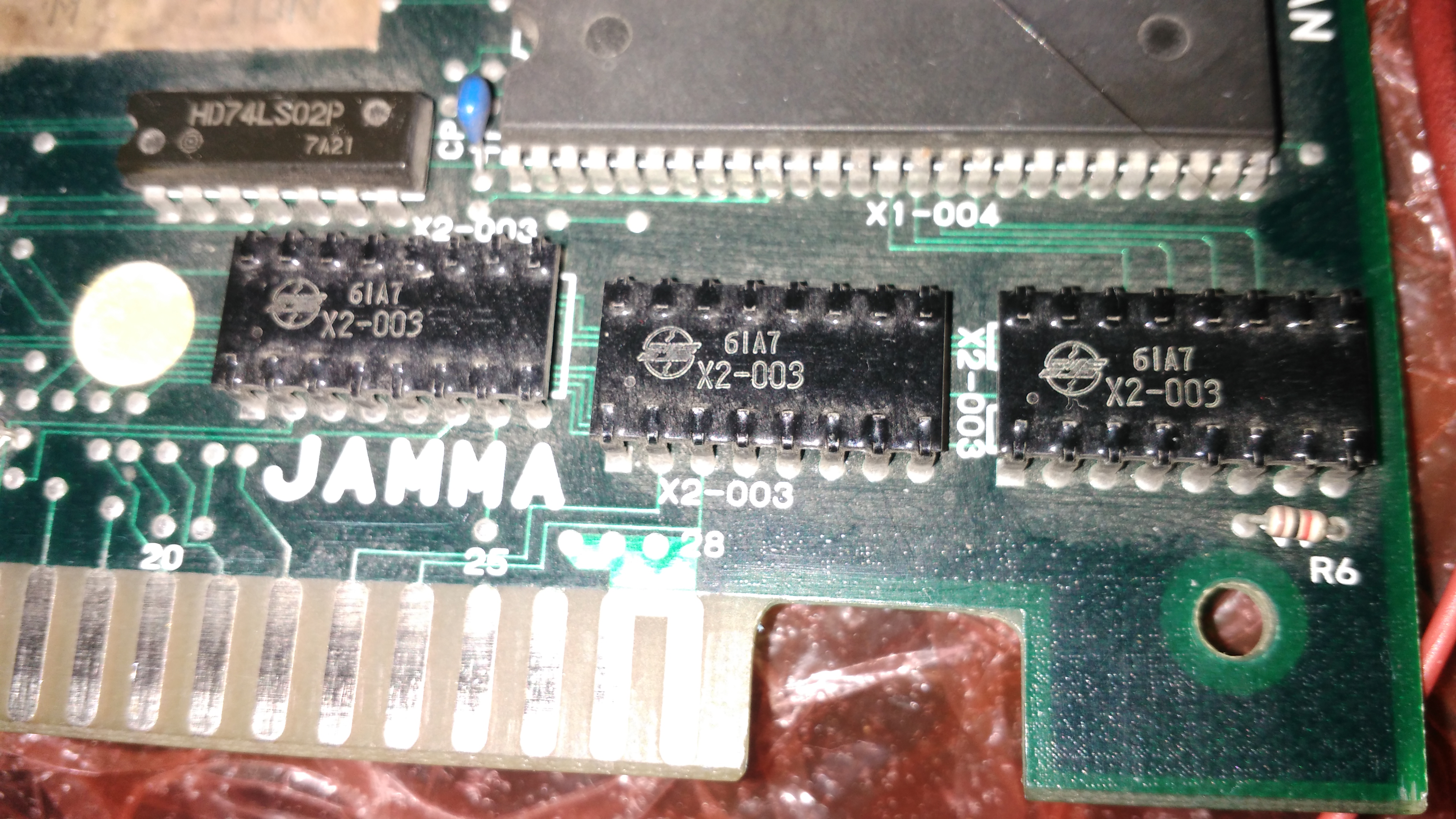
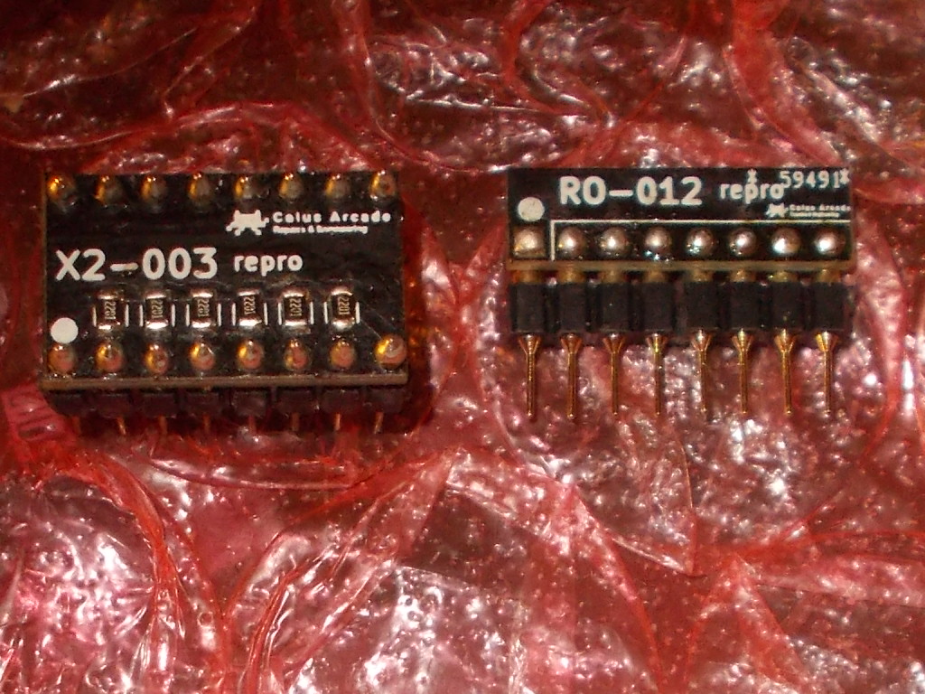
And the ‘X2-003’ :
The first, as said above, is an R/2R resistor ladder acting as RGB DAC, the latter is a capacitors/resistors array used for inputs but, unlike all the others, comes in a DIP16 ceramic package hence quite fragile.Reproducing them was straightforward :
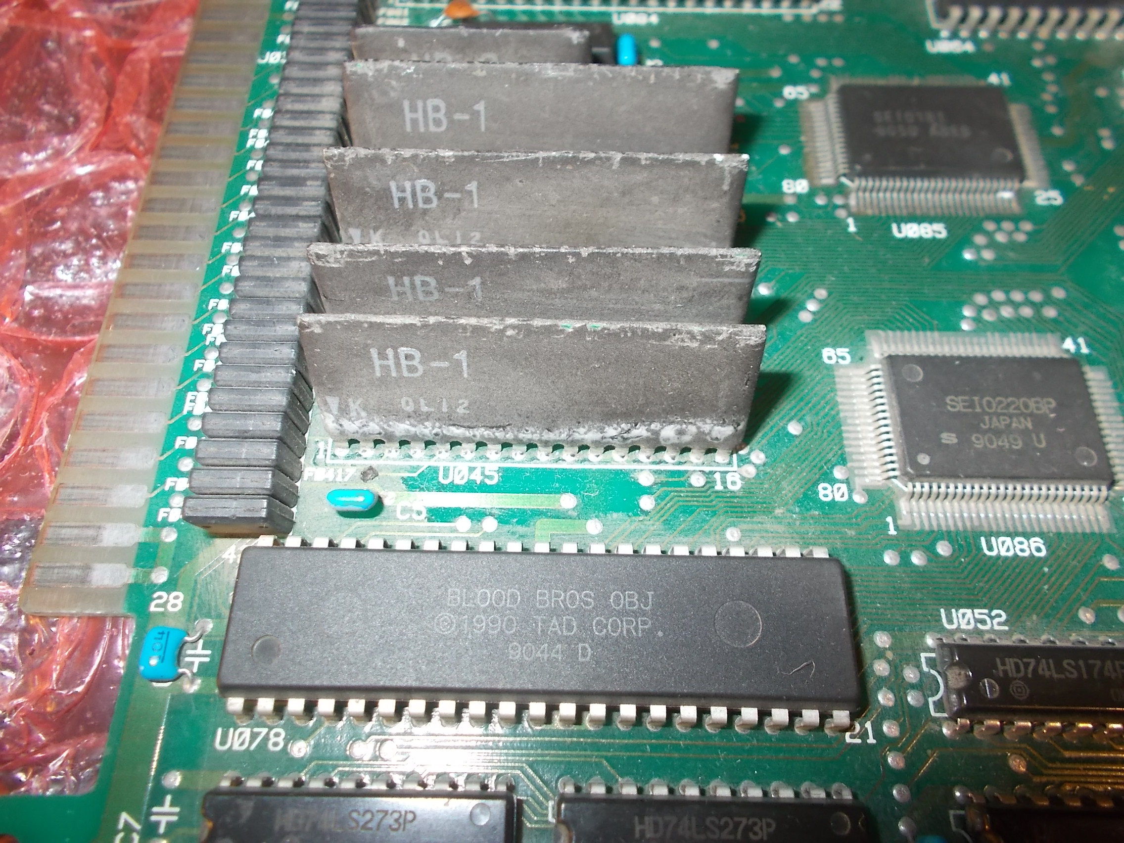
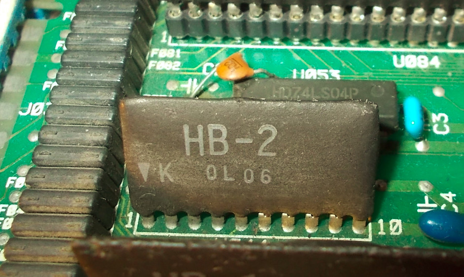
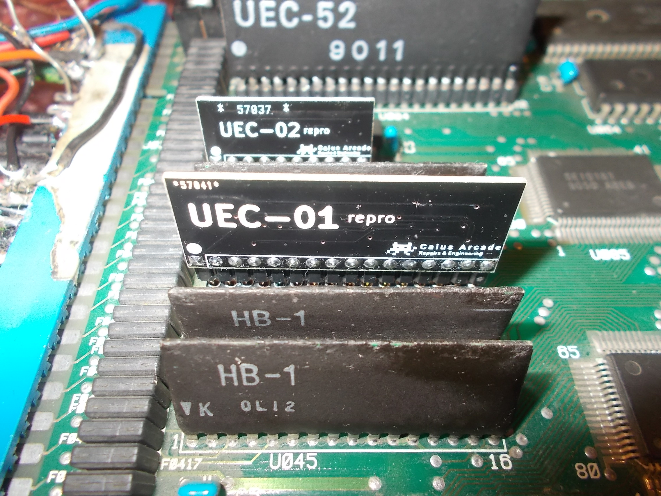
The ‘UEC-01’ and ‘UEC-02’ are two custom ICs you can find on most Seibu/TAD Corporation PCBs also marked as ‘HB-1’ and ‘HB-2’.They are ceramic modules in SIL/SIP package.Here’s how they looks like:
The first handles I/O, the latter drives coin counters/lockouts.Reproducing them was straightforward given the simplicity of their internal circuit so for sake of completeness I took into account also the ‘UEC-02’ although nowadays few people use coin counters:
Testing on a Blood Bros PCB :
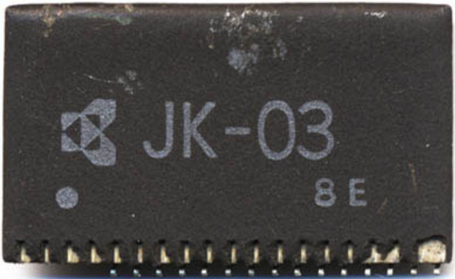
The ‘JK-03’ can be found, instead, on Jaleco MegaSystem1 hardware, it accomplishes the same function of the ‘UEC-01/HB-1’ handling the inputs.It comes in form of a SIL/SIP ceramic module as well (with different pin counting and pitch though)
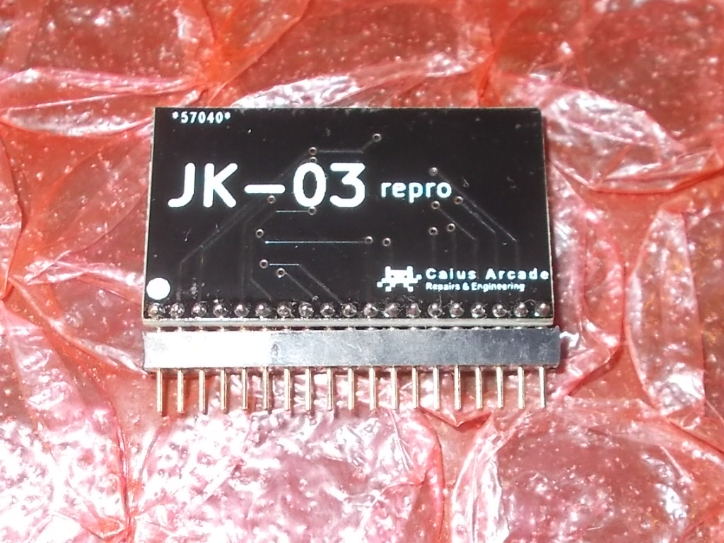
Having no part to analyze I used some available schematics in order to reproduce it:
Due to the lack of a working PCB I could not test it hence volunteers are welcome!
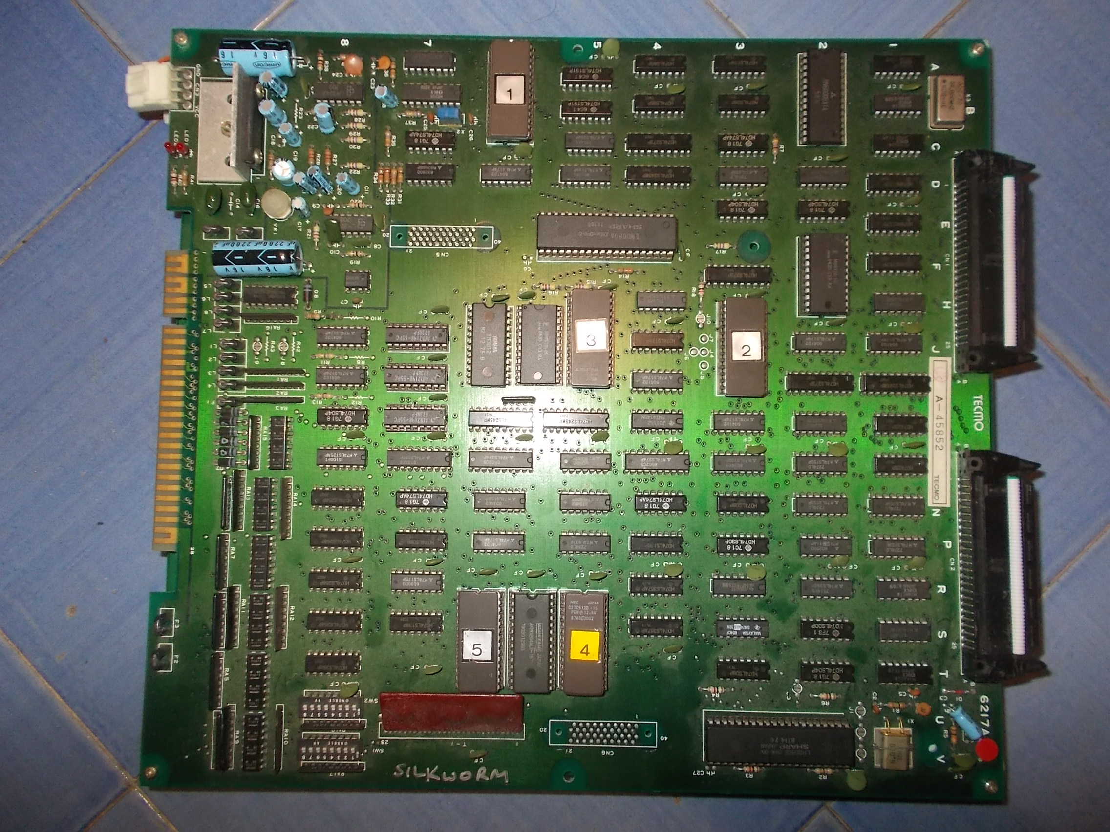
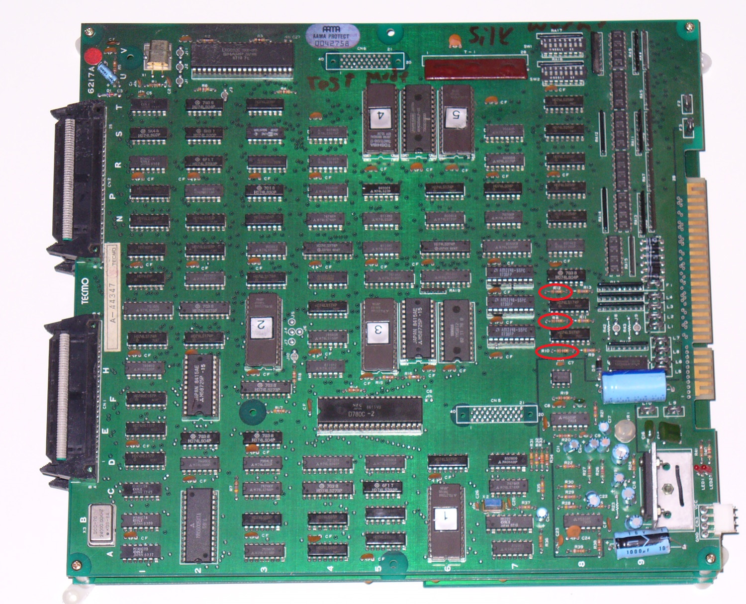
I had this original Silkworm PCB (manufactured by Tecmo in 1988) in a trade some years ago :
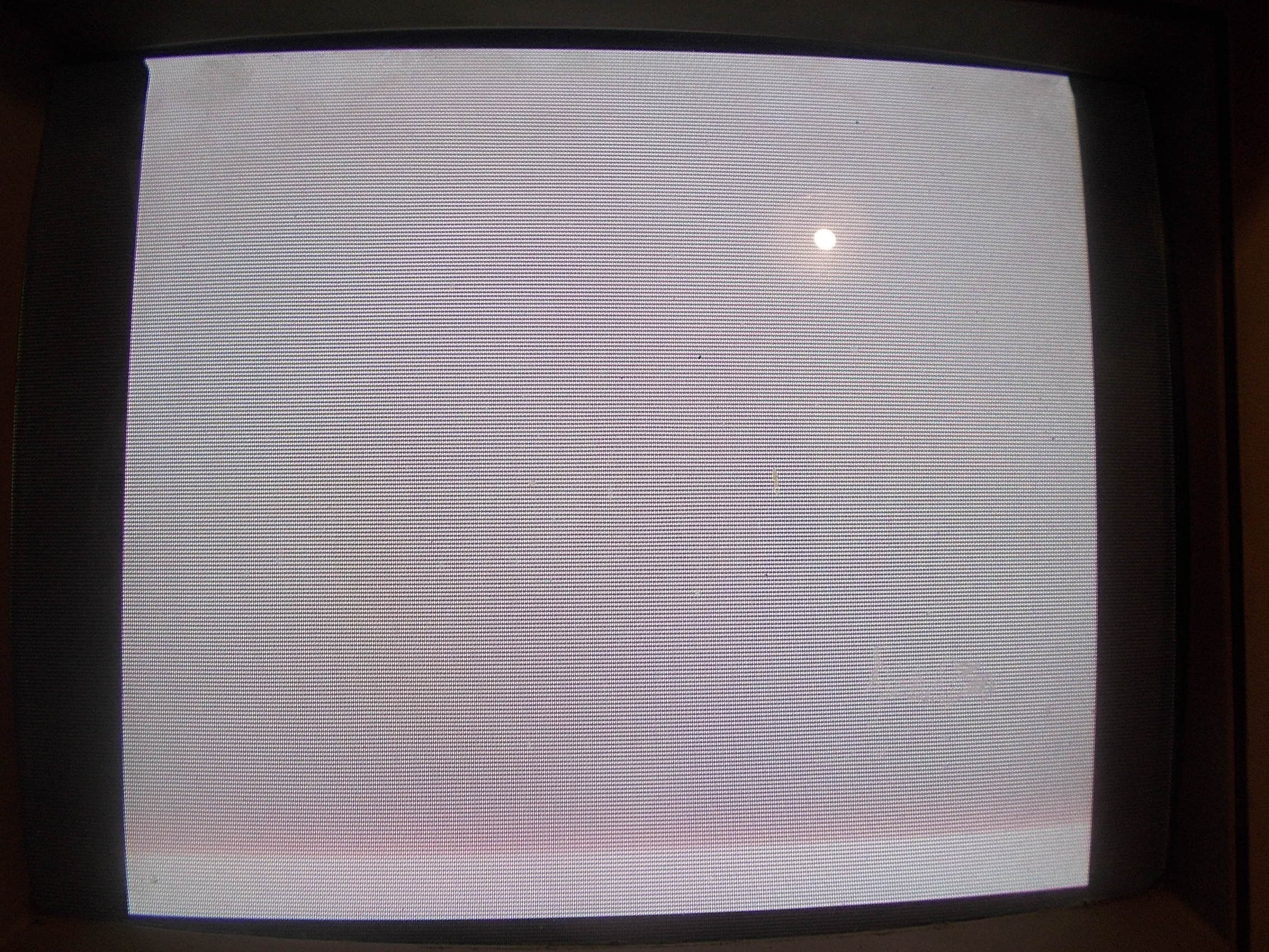
I didn’t know the status of the board since I never looked at it.Quite confident I powered it up but I was immediately disappointed, a solid static blank screen was all I got:
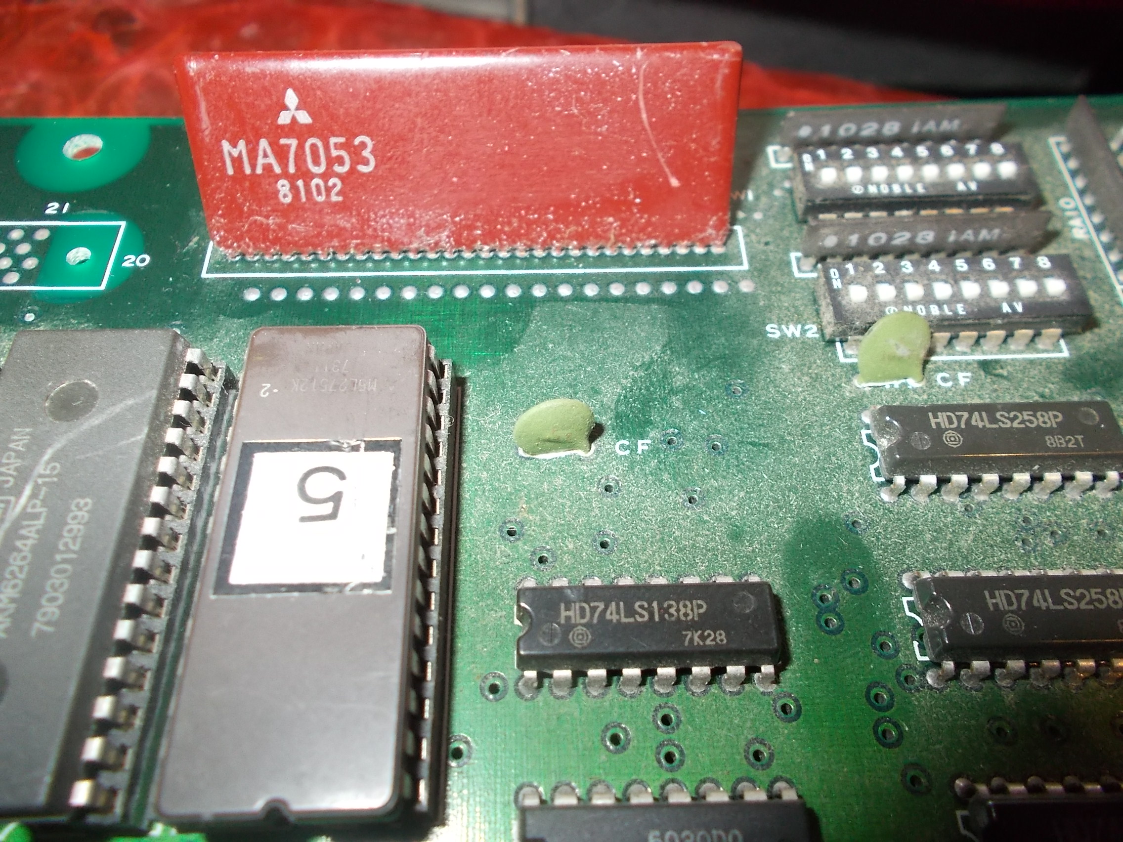
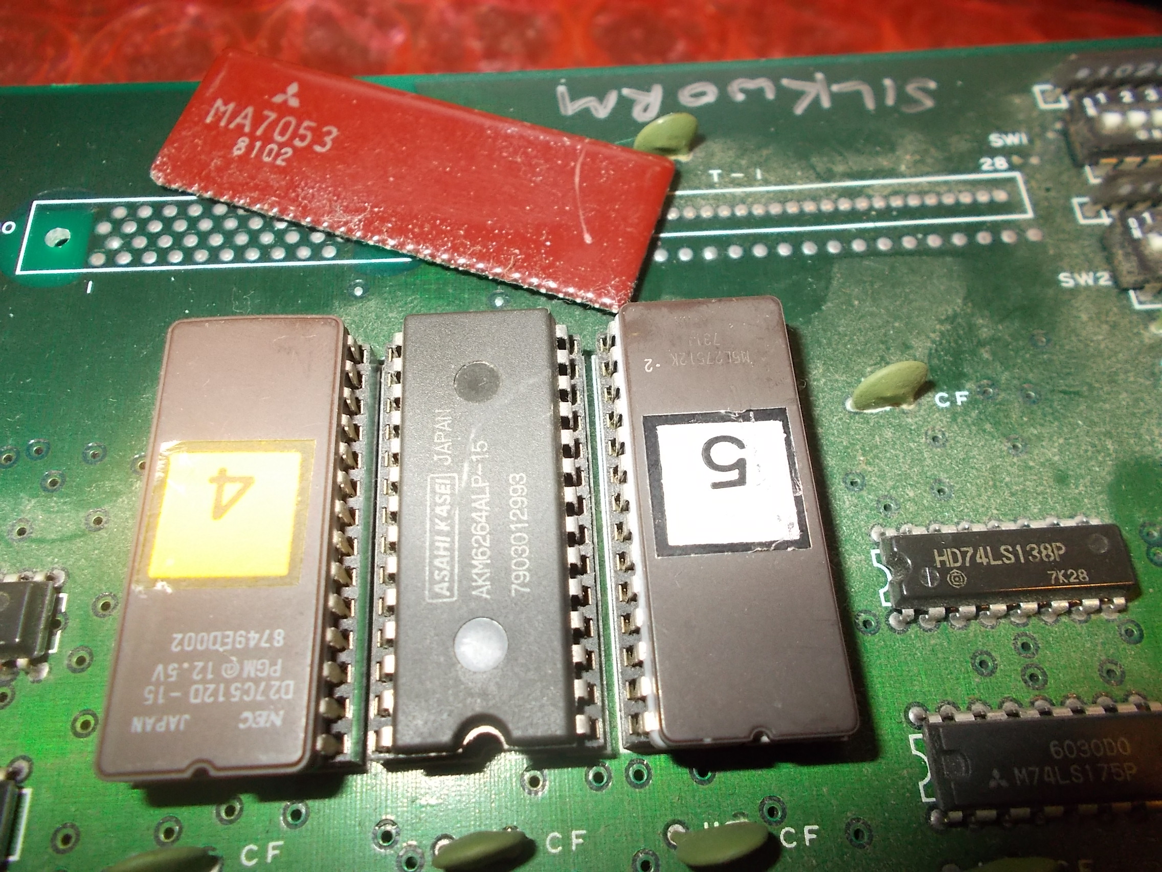
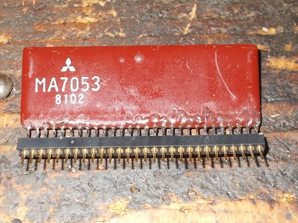
While I was visually inspecting the board I noticed the 28 pin brown SIL hybrid module marked ‘MA7053’ was a bit wonky:
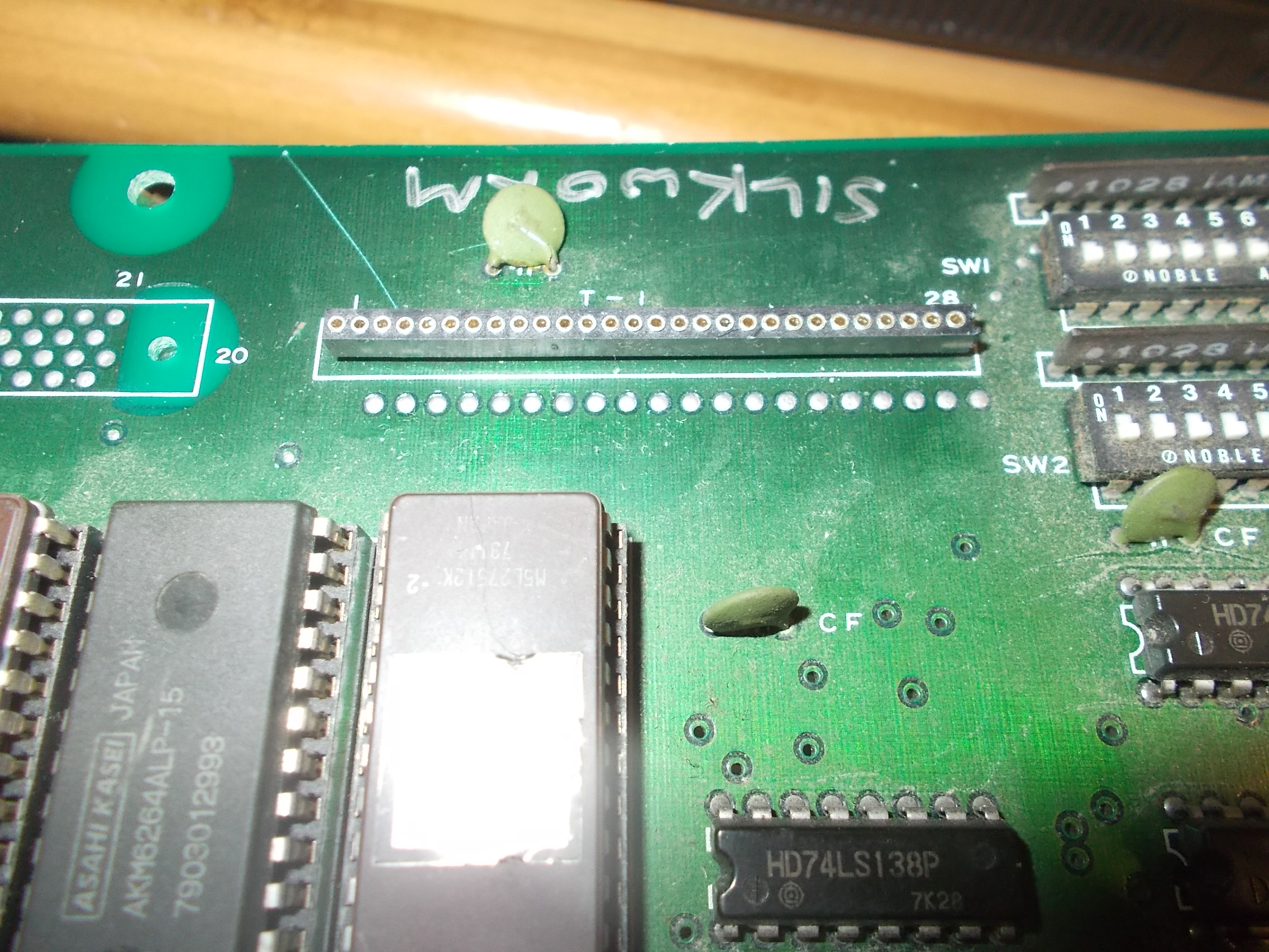
I slightly wiggled it and it fell off:
I installed some 1.778 female pin headers on the PCB:
and patiently soldered the component on a strip of correspondent male headers:
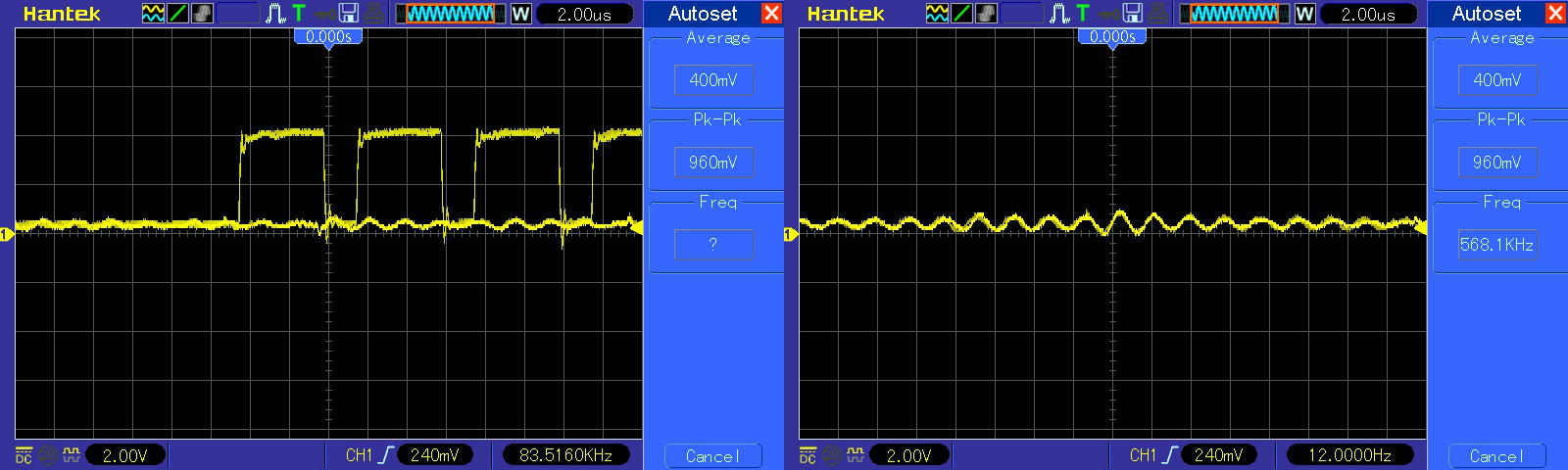
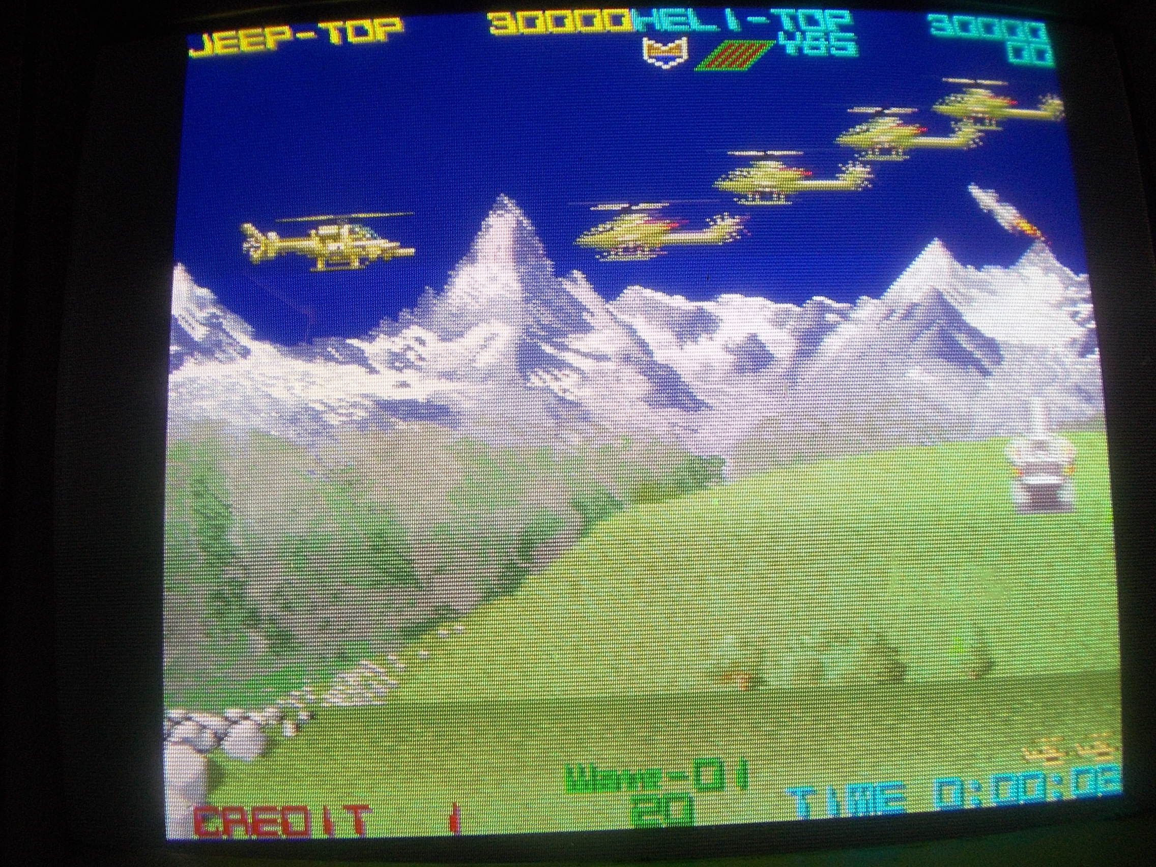
In this way I got the board booting but with severe graphic faults.Color were wrong, sprites flashing (it’s hard to capture this issue with a camera), vertical lines through screen :
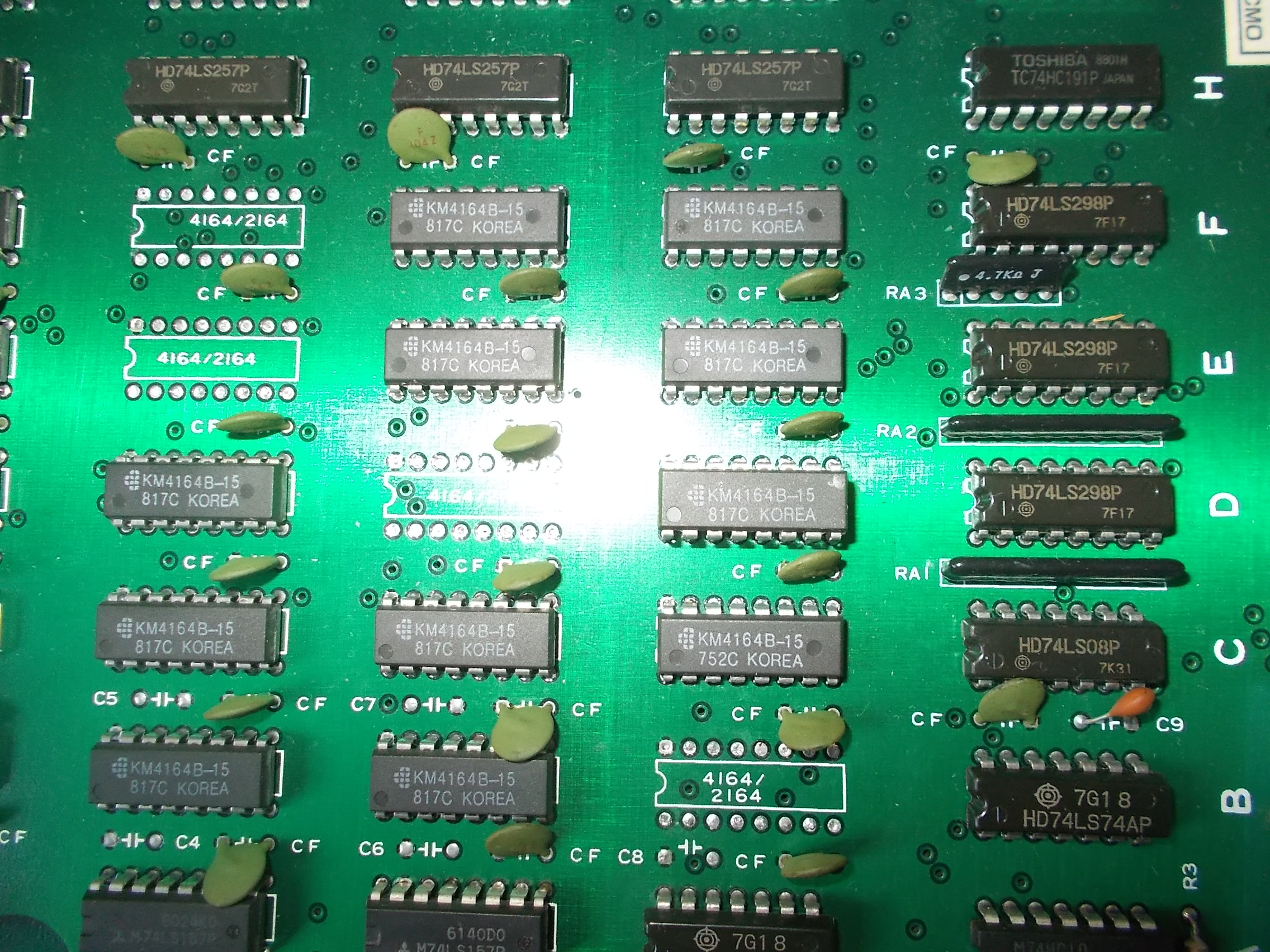
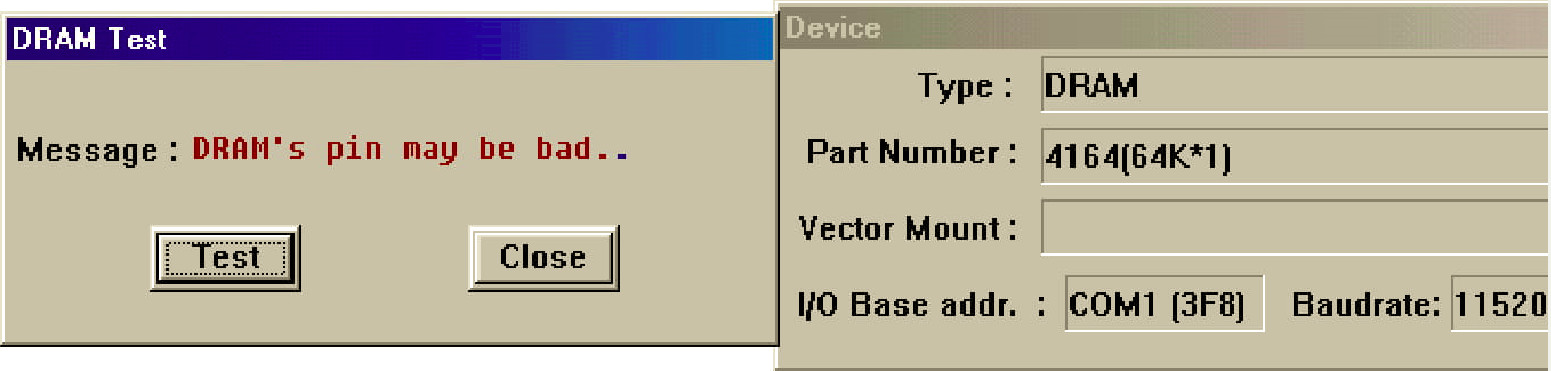
I decided to troubleshoot the sprites issue for first.Studying the hardware I figured out that the line buffer is made of twenty 4164 (64K x 1-bit) dynamic RAMs located on VIDEO board :
Some of them were extremely hot to touch and many showed stuck bit on output:
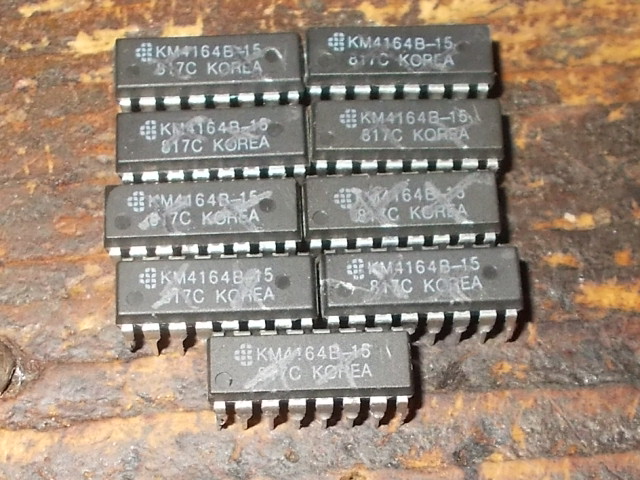
I pulled them all one by one:
Nine of them failed the out-of-circuit testing:
The graphics were correctly drawn now but the colors still wrong :
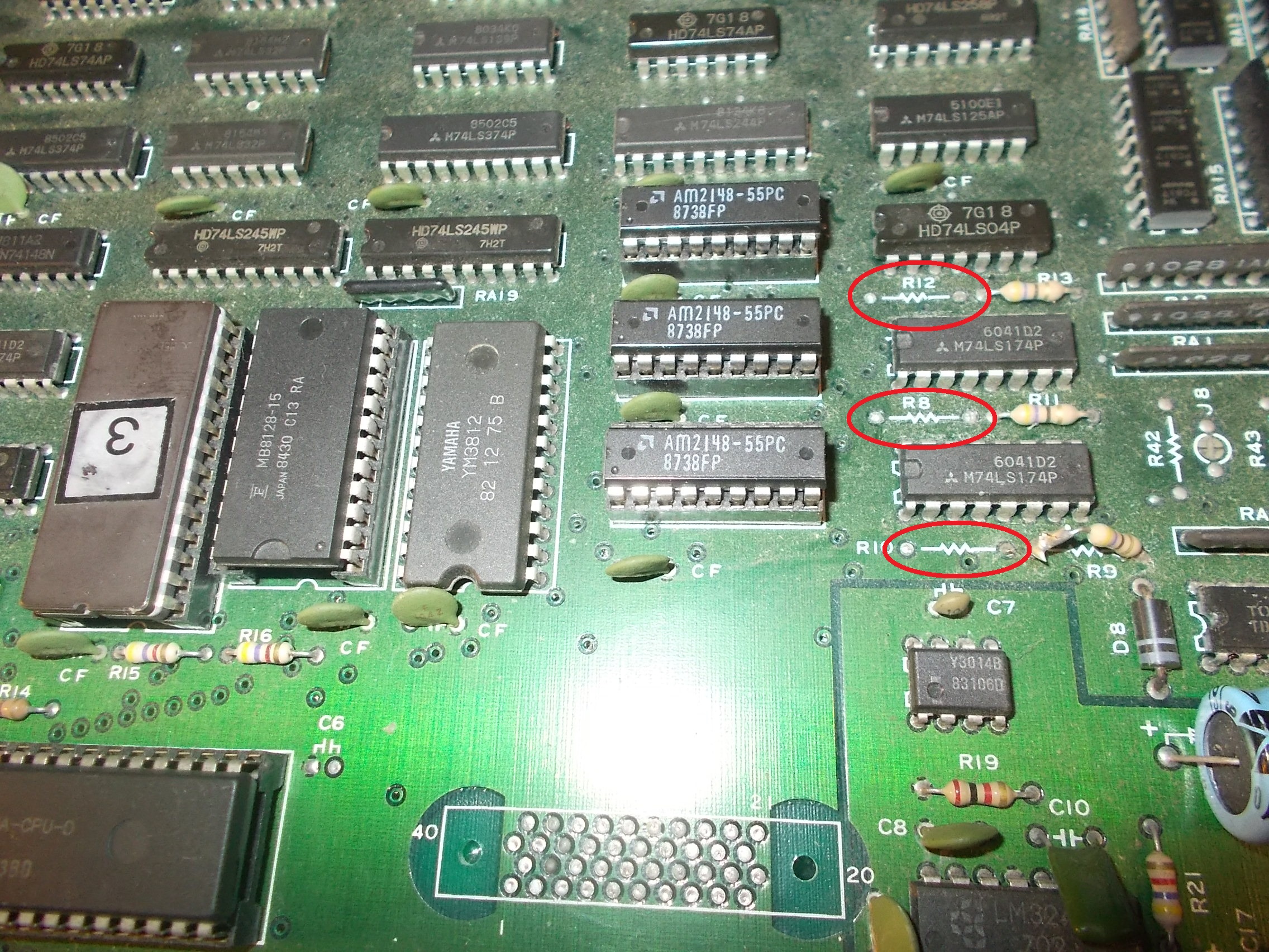
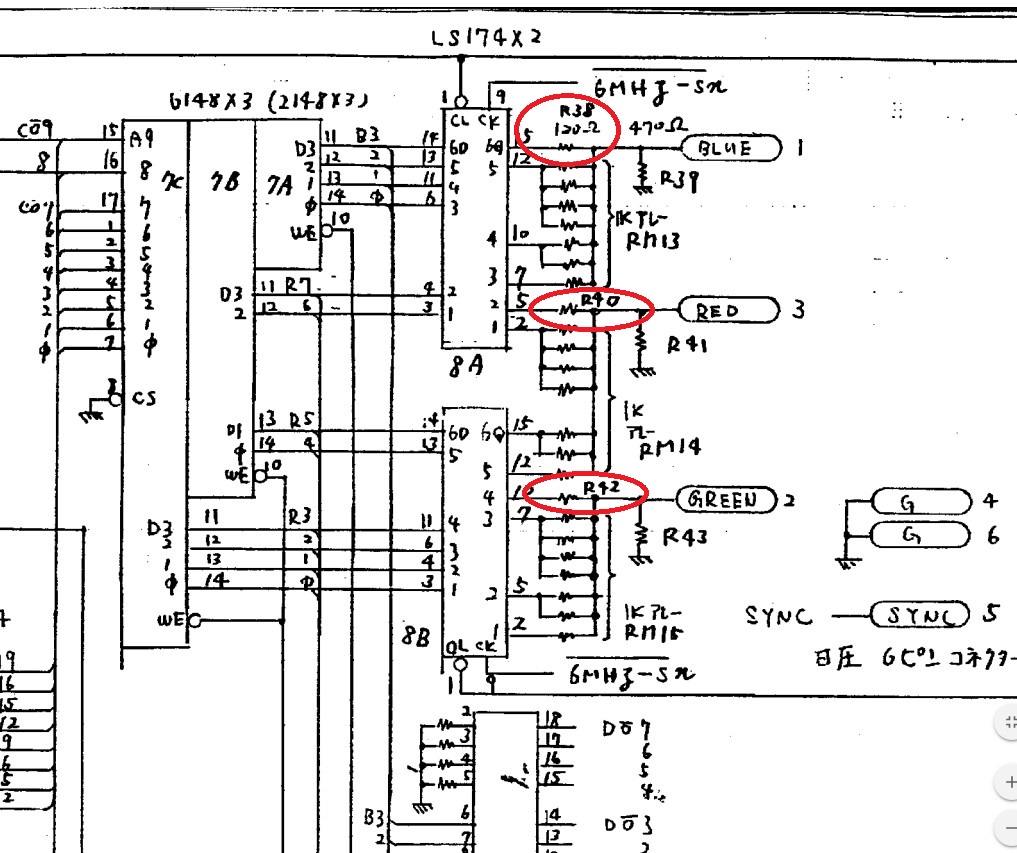
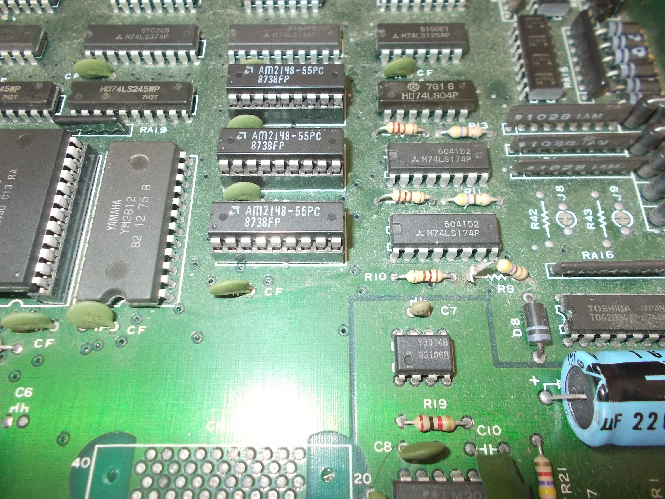
Tracing the three colors back from JAMMA connector I figured out the final part of the RGB DAC circuit where I noticed the lack of three resistors @R10-R8-R12 :
I compared my PCB with some pictures online and I had confirm that the three resistors were really missing on my board:
I didn’t know the correct value of these resistors and schematics were not available so I looked at Rygar ones which runs on similar hardware, they were 120 Ohm as part of the R-2R resistor ladder circuits used as RGB DAC:
I installed the resistors :
This fixed board completely:
Mitsubishi ‘MA7053’ reproduction
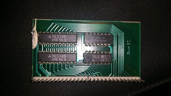
After repaired the PCB I thought this was a good chance to study a replacement of the ‘MA7053’ custom SIL.As often I do in my reproductions I looked at how possibly the custom was re-engineered.I could find two replacement daughterboards.One used on a bootleg PCB :
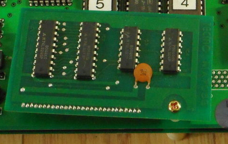
The other one was from an original Tecmo board (pictures kindly provided by ‘monsterlair’, thanks again to him)
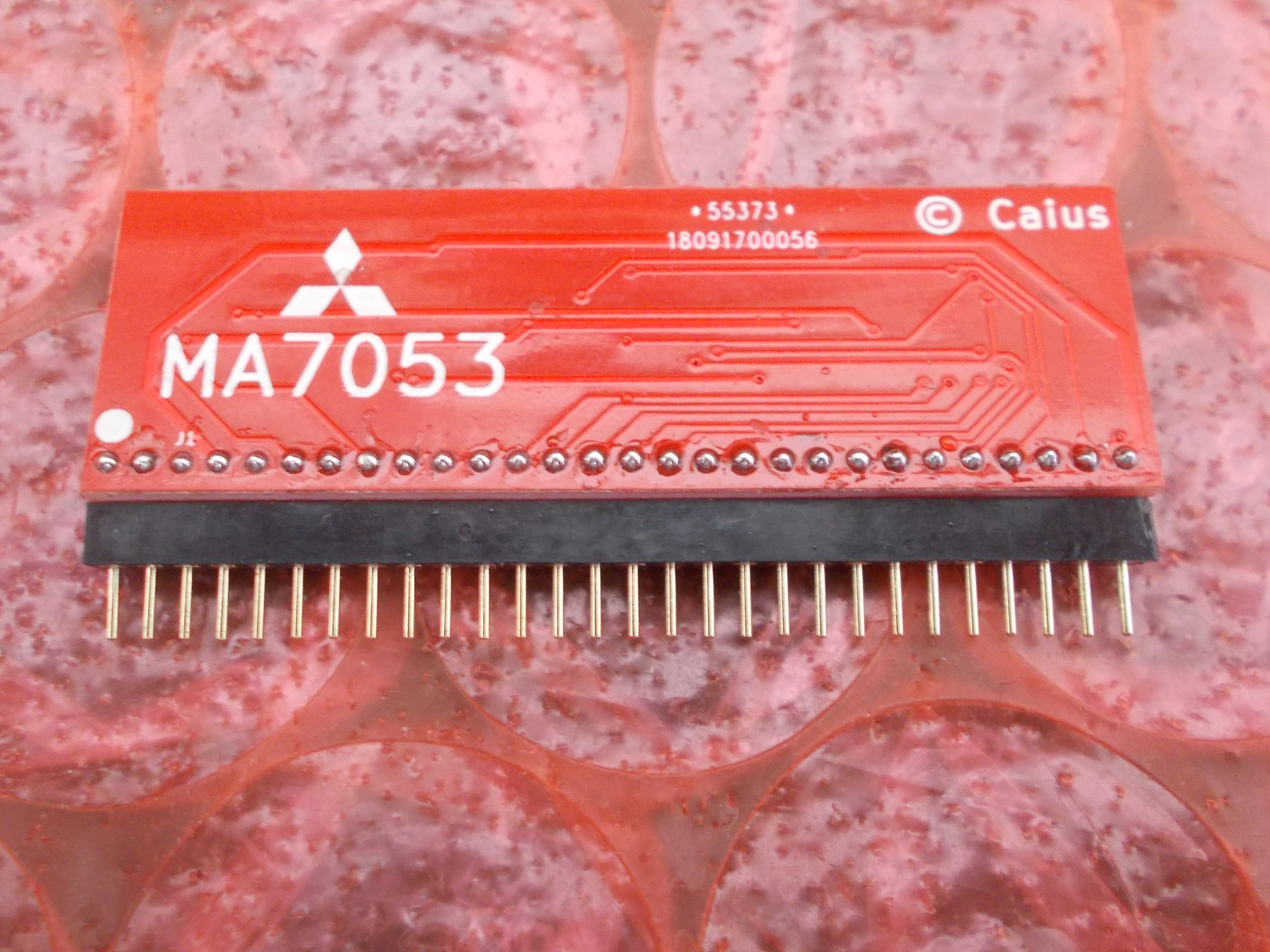
Design were slightly different but they both have same functionality.Technically speaking the ‘M7053’ provides interface between the Z80 main CPU data bus and video memory latching data too.After figured out schematics of the two daughterboards I re-engineered them with surface mounted devices ending up with this result :
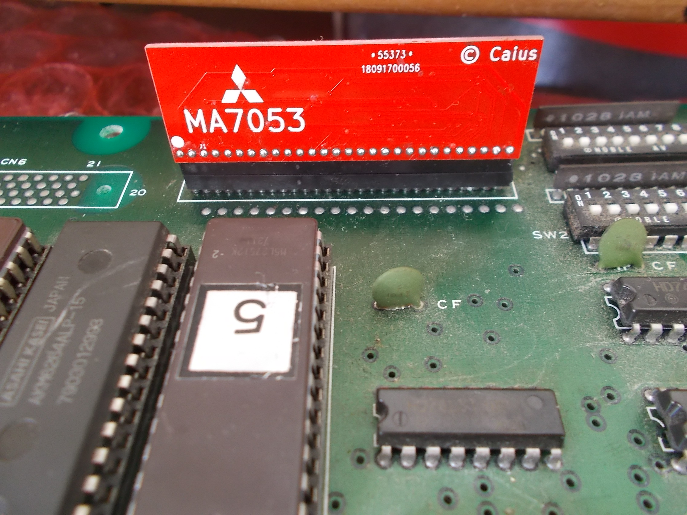
Installed on PCB for testing:
Both designs perfectly works on my newly repaired Silkworm :
The ‘MA7053’ is used for sure on these PCBs:
Gemini Wing
Rygar
Silkworm/ Back Fire
But it could be present also on other Tehkan/Tecmo boards so any addition is welcome from all of you arcade collectors/enthusiasts.