Sunset Riders repair log #4

 PCB Repair Logs, Repair Logs  Comments Off on Sunset Riders repair log #4
Jun 182016
 

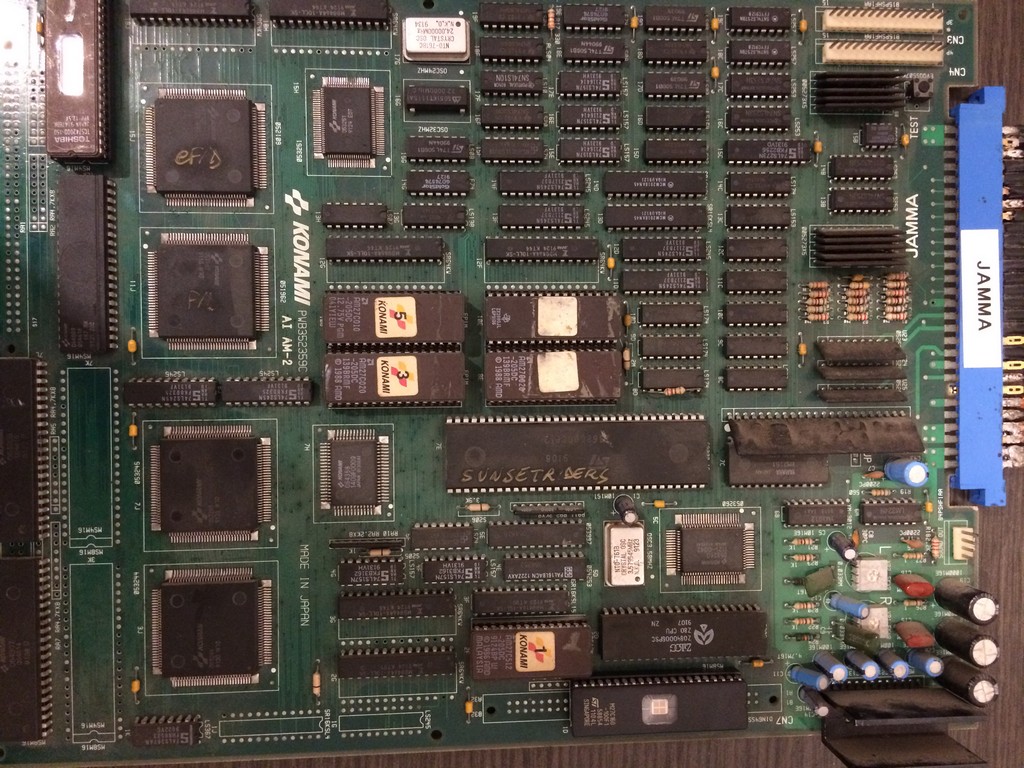
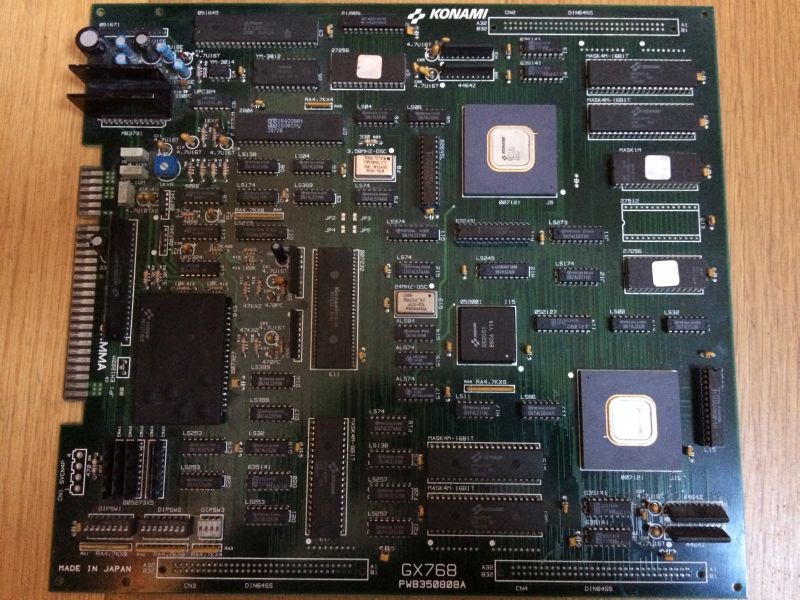
I got this pcb for a repair.

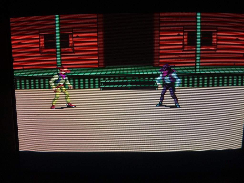
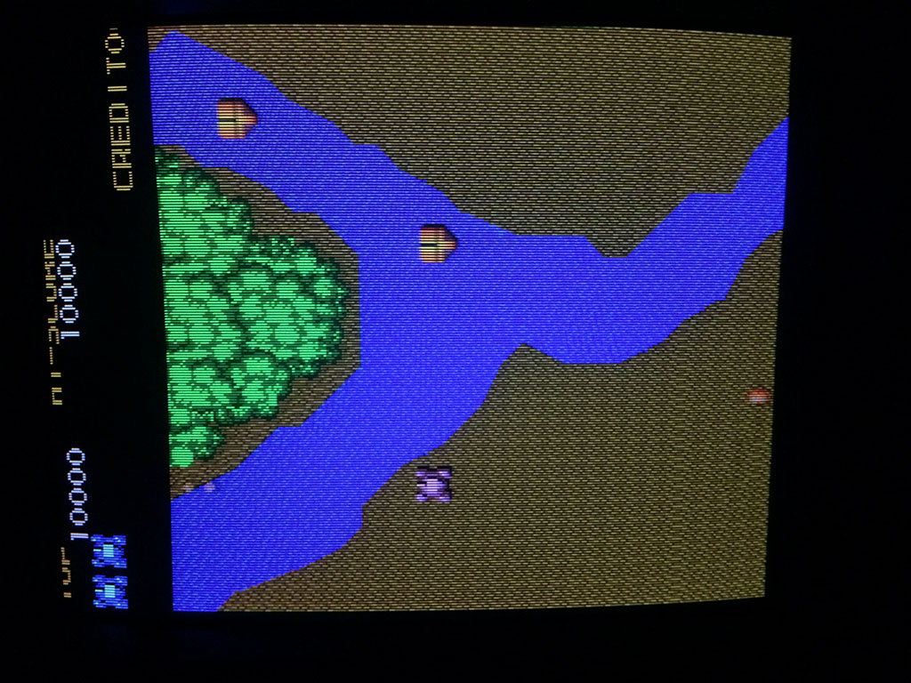
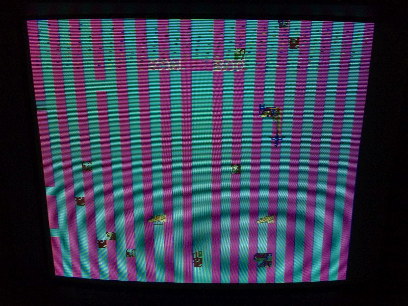
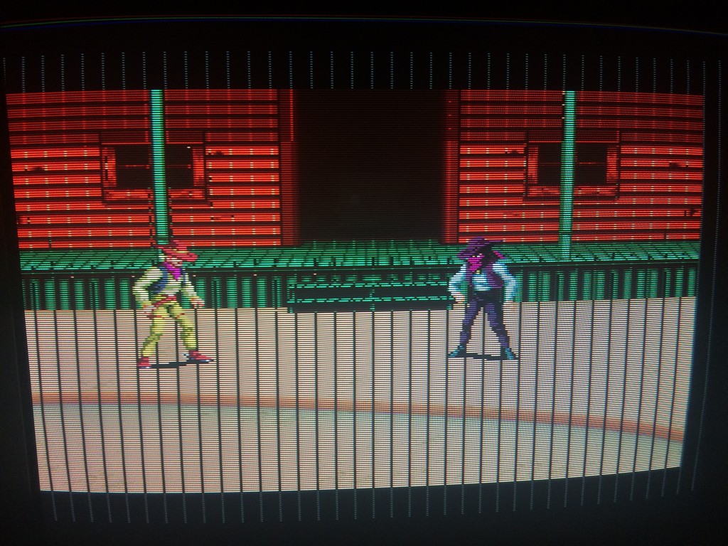
Gameplay was fine but graphics had black lines and music had a lot of white noise.

ssrider


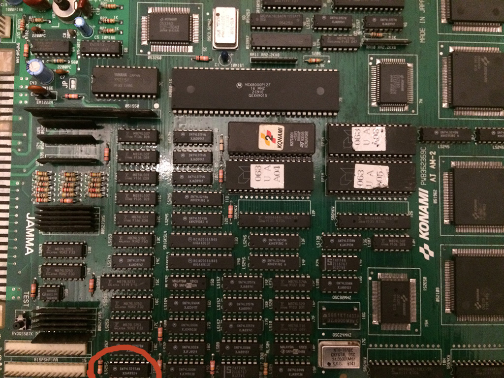
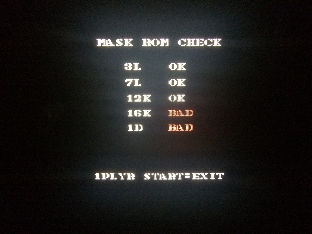
I ran the maskrom check and it reported two roms as bad, one of which was infact the rom with the sound data.


ssrider2


It doesn’t mean necessarily that the maskroms are bad, can be also that the custom chips have some pins not soldered correctly or the chips themselves being faulty.

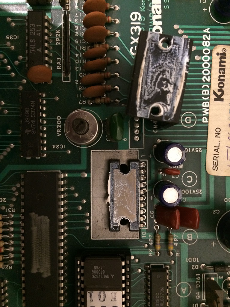
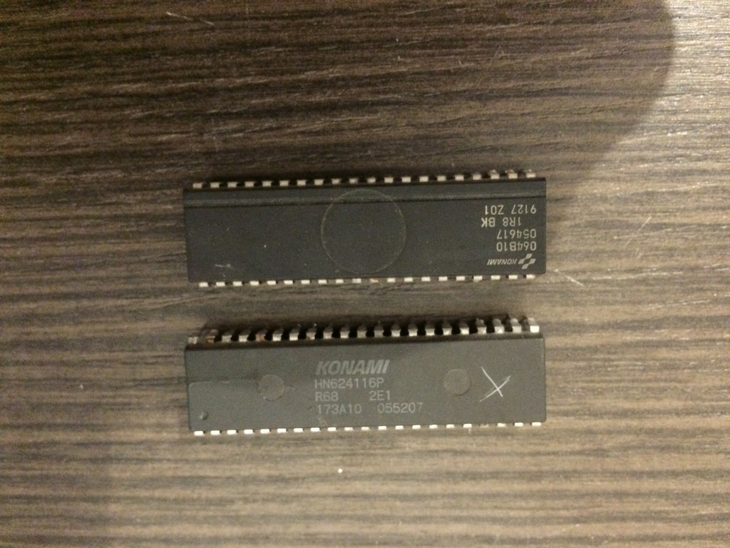
The only way is to desolder the maskroms and check on a programmer if it reports pins not connected which means that the chip internally is broken.

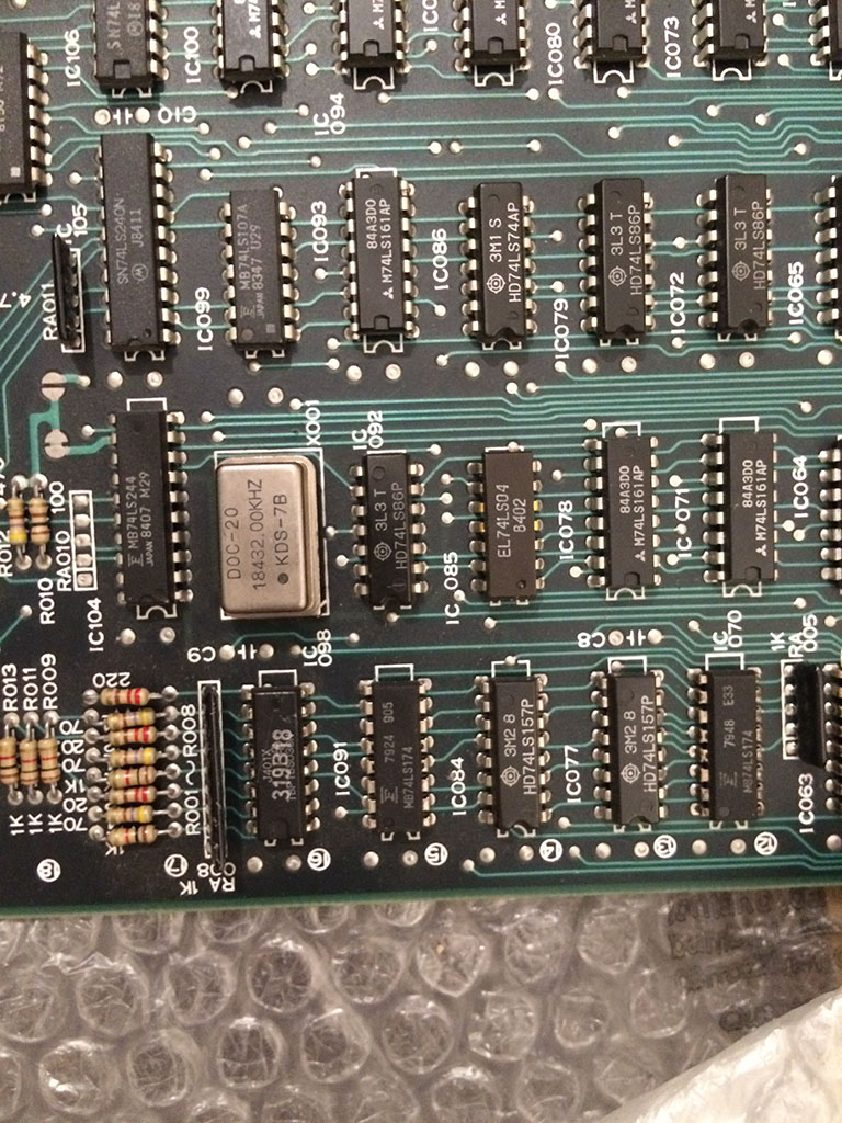
After a check with the romset, I decided to dump rom 16k as 27c400 (4mbit eprom with maskrom pinout) and rom 1d as a 27c800 (8mbit 16bit eprom).

Both were reported as having pins non connected properly.

ssrider3

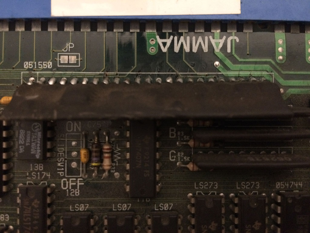
So I replaced maskrom 16k with a 27c400 and the markrom at 1d with a 27c160 eprom (16mbit 16bit eprom) after having doubled the original file in order to prevent the game to access the empty space in case the additional addrr line is not connected to GND or 5V.

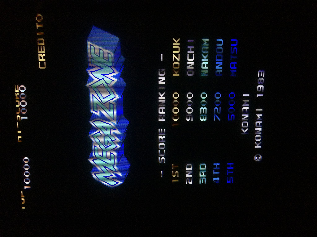
This fixed 100% the game

ssrider4

ssrider5

Mar 292016
 

Got a very clean Megazone pcb for a repair.  The board was in near mint conditions but it didn’t boot and also the Sync was missing.

Looking at the schematics available online, I noticed that the quartz responsibile for the CPU clock and sync was the one placed on the bottom board.

Tested with my frequency meter and it was dead.

It is a very rare 18.432mhz OSC which to my knowledge is used only by early 80s Konami boards.

megazone


Luckily I had a Double Dribble which I used for spare parts which had the very same OSC.

After changing it, the game booted perfectly.

megazone3

megazone4

For you information, if you try to install the more common 20Mhz OSC, the colours are off and the scrolling is jumping often, so unfortunately it’s not a good replacement.

The board had no sound but I immediately noticed that there was no noise coming out of the speaker which is the evidence of a faulty amplifier.

The amplifier is infact the very unrielable LA4460N, so after confirming the the music could be hear on input pin 2 , I exchanging it and fixed completely the game.

megazone2


X-Men repair log #2

 PCB Repair Logs  Comments Off on X-Men repair log #2
Mar 242016
 

The board played completely blind.

With a logic probe I tested all the 74Ls07 which had fixed input and outputs as expected, therefore no activity at all.

Tested the clock (pin 11) on the 74LS273@9C and 10C and it was fixed high.

xmen-schems

Unfortunately the schematics of the game found in internet are not complete, so I had to trace back manually and found out that the output pin 14

of the 74LS04@17E was stuck, while the input was floating.

xmen


Replacing the chip with a good known one didn’t fix the problem!

So I looked on the back of the pcb and found that a pin of a chip was touching the line of the output it shorted it !

After lifting the pin, the pcb showed the game in colours but all the screen was blocky.

While searching for the source of the problems I shorted two pins of a custom chip by mistake and the pcb rebooted without any issues.

It was clear it was some kind of reset problem for the graphic chips.

The 68000 had it’s own circuit but the customs had a separate reset.

Looking back on the schematics, I found out that the system reset was given by the custom 051550 which I couldn’t find on the board….

Infact it was missing and I didn’t notice!

Soldered a new one from a scrap pcb and the game was fully restored!

xmen2


Teenage Mutant Ninja Turtles – Turtles in Time repair log #2

 PCB Repair Logs, Repair Logs  Comments Off on Teenage Mutant Ninja Turtles – Turtles in Time repair log #2
Mar 122016
 

Easy job: the game soon after POST coined up immediately.

Ran the I/O test and the coin button didn’t work (but it showed a 0 instead of 1).

Testing pin 16 of Jamma connector (coin input) showed that it was stuck low all the time.

Tracing back with the multimeter I found out that the responsible for coin inputs was a 74ls257 TTL @19C which I replaced.

That fixed the problem.


TMNT

Haunted Castle repair log #2

 PCB Repair Logs, Repair Logs  Comments Off on Haunted Castle repair log #2
Dec 282015
 

Got this pcb from a friend of mine for a repair

haunted

The pcb had already all the sram chips repaired and some flying wires underneath because of broken traces.

Upon boot up, it constantly reset with this message:

haunted1

First thing was to test the socketed sram chip 6264 near the 2 big customs but as expected they were good.

Tried to flex the pcb and it booted with wrong palette sometimes

haunted2

Surprisingly once it booted it could be played with wrong palette all the time until the next boot.

So the code did only a check at the beginning.

After pressing and flexing everywere I found out that the game booted only when I pressed the Hybrid module 007327

I discovered looking underneath that the module has some small srams and looking at the schematics this is confirmed.

haunted_007327

I turned out that one pin had a subtle loose contact. I reflown brutally everything to make it more resistant against shocks.

haunted3

Booted the game and I was welcomed to a perfectly working game

haunted4


haunted5