Operation Wolf repair log #3

 PCB Repair Logs, Repair Logs  Comments Off on Operation Wolf repair log #3
Apr 102020
 

Another few Operation Wolf boards in at the moment. This one is from Unit504.

There is a nice little tag on this telling me the faults which really helps me keep all these boards together and where to start looking.

First job was to look into the gun shot register issue.
I did a quick test and could see the screen flash when the trigger was pulled so I knew that wasnt the fault
Following the circuit I come to the 74F74 IC which is used to latch the gun co-ordinates.

I normally wouldn’t start looking at this part but it was already socketed so decided to pull the chip and test it. It failed an out of circuit test.

I replaced this with a 74ALS74 and it seems to be be fine.
Now all the gun shots register as expected.

Next onto the sound.
None of the sounds were working at all and I didnt believe that all the seperate circuits for making sounds would be dead so looked a bit closer at the CPU side of things.
First off I checked the ROM and it dumped out fine.
Next the RAM. An inspection of the RAM showed signs of corrosion

I removed and tested it and thankfully it failed

Looks like that corroded pin has broken contact somewhere. Anyway, replacing the RAM brought all the sound back to life and completed this repair.

Lightning Fighters repair log #4

 PCB Repair Logs, Repair Logs  Comments Off on Lightning Fighters repair log #4
Mar 242020
 

I got a Lightning Fighters PCB with GFX problems. As you can see, major colors and layers issues:

1) Probing the Konami 053251 custom chip revealed some weak signals on a few pins. This chip is a priority encoder, it deals with colors and layers and seems to be prone to failure in more and more boards of that generation. Unfortunately, you have to find a donor board of the same era to get a working one (good thing anyway is that it is used in a pretty good amount of Konami games).

Here is the result after swapping it with a good one:

2 & 3) Colors and layers are now fixed but we have some jailbars on sprites. This looks to be a sprite’s data issue. Probing the mask ROMs revealed missing signals on a few data lines for 939A05 and 939A06 ROMs. I replaced them with two burnt 27C400 EPROMs. Board is now fixed:

Here is an overview of the chips I had to replace on the board:

Feb 122016
 

Here is a picture showing a recently repaired Rastan PCB with the replaced chips highlighted in red.

rastan2-5

I will explain every step of the repair process here:

1) When powered up, the game was starting but was constantly rebooting after about 5 seconds. I checked the reset pin on the CPU but it was constantly high so that seemed not related to that. I checked the signals on the 2 CPU RAMs @ IC10 and IC22 (2x TMM2063 – 64kb) but nothing seemed suspicious. Anyway, piggybacking the one @ IC10 made the game not rebooting after 5 seconds but after a longer time. That was sufficient to let me think it may be faulty so I desoldered the RAM and it was tested bad on my programmer. Replacing it by a new one made the game working and not rebooting again and again. Good.

2) Well, the game was now playable but there was no FM sound (so no music at all), only voices were audible. Schematics are available online so I could see that the FM sound is generated by the YM2151 @ IC63 then it goes to an YM3012 DAC @ IC78 then it goes to a TL074 op amp @ IC100 to finally going to the MB3731 amplifier @ IC101. Outputs signals looked healthy at the outputs of the YM2151 and I had correct sound for the voices so the issue should be located before the mix between FM and voices signals, so before the amplifier: more probably within the DAC or the op amp. The TL074 is composed of 4 operational amplifiers:

rastan2-6

I noticed that every of the 4 output signals on the TL074 @ IC100 were looking weird with a negative voltage (between -1 and -2 V). There is another TL074 chip on the board that is related to the voices and every outputs showed a positive signal of approximately 2.5 V. That was suspicious so I desoldered the TL074 @ IC100 and replaced it by a new one and the FM sound was back ! (the signals on every 4 outputs were now showing a positive analogic signal of approximately 2.5 V).

3) and 4) Ok, so then the game was fully playable with perfect sound but there was some graphical glitches on a few items, as seen here in the attract mode:

rastan2-3

I have a previously repaired Rastan PCB that had one of its gfx mask roms replaced by an hacked 27C010 EPROM so, due to the nature of the problem here (glitches on only a few particular items), I suspected one or multiple MASK ROMs to be faulty. I started replacing these ROMs with the ones from my working Rastan PCB and got the gfx working perfectly after replacing B04-07 @ IC14 and B07-08 @ IC27. As noticed in my previous Rastan repair log, the gfx ROMs on this board are 128kb fitted into 28 pins chips. Finding blank chips with these exact specs is hard nowadays so I used 128kb 32 pins 27C010/27C1001 EPROMs as replacement (I could use a 27C1000/27C301 EPROM to make the modification even easier but I didn’t have one remaining then). To fit them on the 28 pins sockets present on the Rastan board, you have to make the following modifications on every EPROM:

If you use a 27C301 or 27C1000 non-JEDEC EPROM (simplest way):

  • Connect pins #30, 31, 32 together and connect them to pin #1 with a small wire.
  • Connect pin #2 to pin #16 with a small wire.

If you use a 27C010 or 27C1001 JEDEC EPROM:

  • Connect pins #30, 31, 32 together and connect them to pin #1 with a small wire.
  • Gently bend pin #24 so it won’t plug into the socket and connect it to pin #16 with a small wire.
  • Solder a small wire on pin #2 that you will plug into pin #22 of the socket.

I did these connections on the underside of the chip. Here is how it looks on my 27C010:

rastan2-2

And this is how it looks after the 2 chips plugged in:

rastan2-1

Now the gfx are fully restored, as well as the rest:

rastan2-4

Oct 232015
 

I recently repaired a friend’s dead Ikari Warriors PCB.

It had a black screen on boot with no sound.

This game is a bit tough to diagnose as it is composed of 3 PCBs mounted on each other. Fortunately I had another working Ikari Warriors PCB so I could swap boards in order to track which board(s) were faulty. Top board and middle board were tested ok on my working Ikari so, fortunately, only the bottom board was faulty.

Here is a picture of the faulty bottom board with the faulty chips I replaced in red. I’ll explain every step below.

ikari1b

1. There was something that was avoiding the game to boot on that board. First, in order to reduce the field of investigation, I disconnected each of the 3 connectors on my working Ikari to see when the game was booting or not. It was booting only with the two bottom connectors on, the one above is only related to the sprites and doesn’t prevent the game to run. So I needed to focus on and around these two bottom connectors. I checked the signals on every pins to track a possible missing signal. After comparing the signals, I found one that was “floating” on my faulty board and was pulsing on my working board. This was connected to pin 9 of the 74LS367 (marked 1 on the PCB picture). Piggybacking a working chip on that one bring the game booting back again !

2. Well, the game worked but the characters had missing legs and were always looking down whatever movement you did, enemies had wrong visuals and background scrolling was jerky…

As previously seen, the sprites are related to the upper connector. I started to check the signals on the upper part of the board and quickly found a 74LS273 (marked 2 on the PCB picture) with a seemingly dead output (my working board confirmed this). Piggybacking the chip with a new one bring back the characters’ movements and visuals. I still had the jerky scrolling though…

3. This one took a bit longer as I had no real idea where to look on the board for the chip that was responsible of this jerky scrolling. After more than an hour, comparing signals between the working and faulty boards, I found a suspicious signal on a 74LS86 (marked 3 on the PCB picture). This was indeed a dead output (pin 6). Piggybacking a good chip on it bring back the smooth scrolling.

As an example, here is what the signal looked like on the pin 6 of that 74LS86 before and after replacement.

ikari4

Board is now fully fixed.

Sep 042015
 

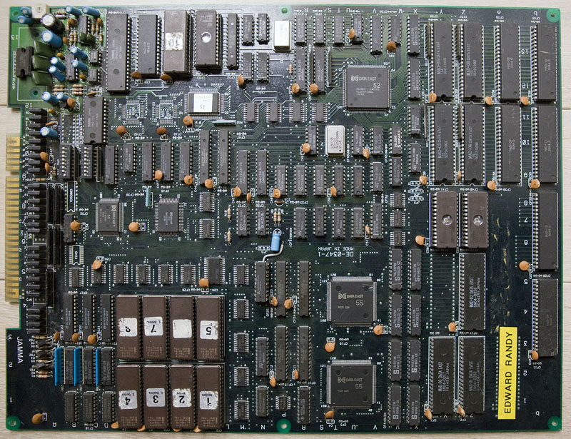
I got an Edward Randy with a black screen (but partial sound).

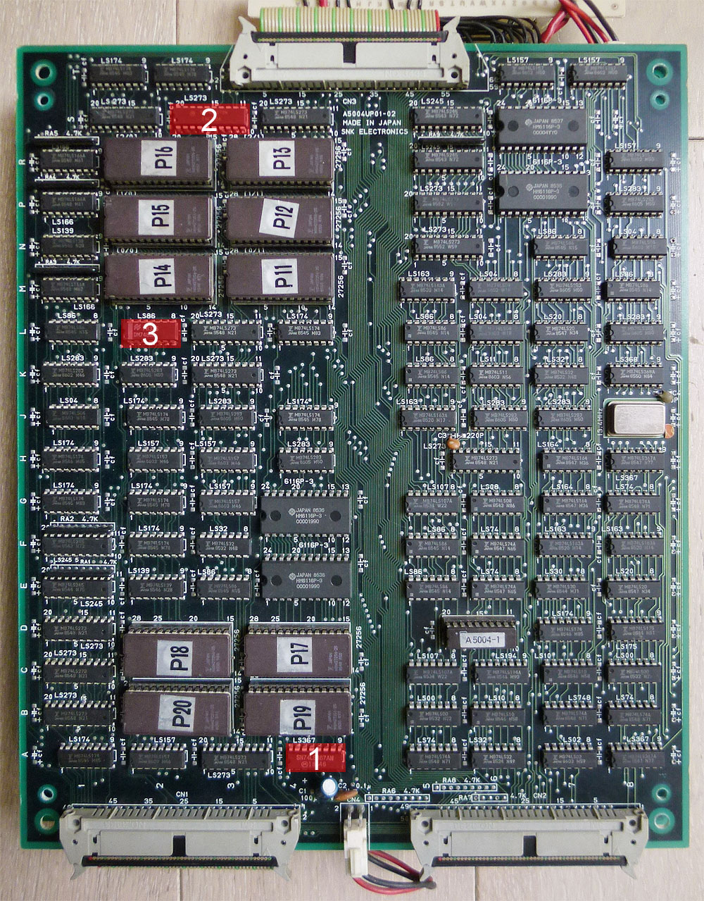
After a few checks with my scope, I quickly found a PAL @ location N5 with no signals on all of its outputs (BUT signals on its inputs).

edrandy1

As PALs from this game are not available yet online, I looked for other games that possibly shared the same hardware/system in order to try using a similar PAL.

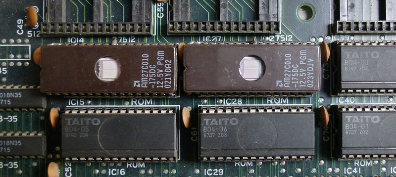
And yes, that system is listed as “Data East Caveman Ninja Hardware” in MAME and some of these games got their PALs dumped. It was the case of Caveman Ninja and Robocop 2 that shares an almost identical PCB layout than Edward Randy (there are only a few differences in the GFX ROMs part).

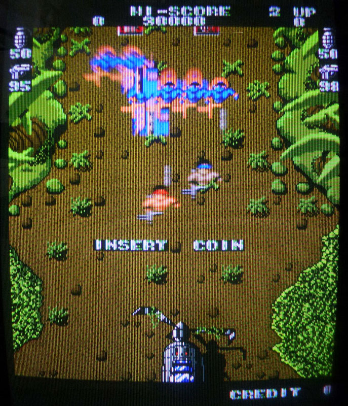
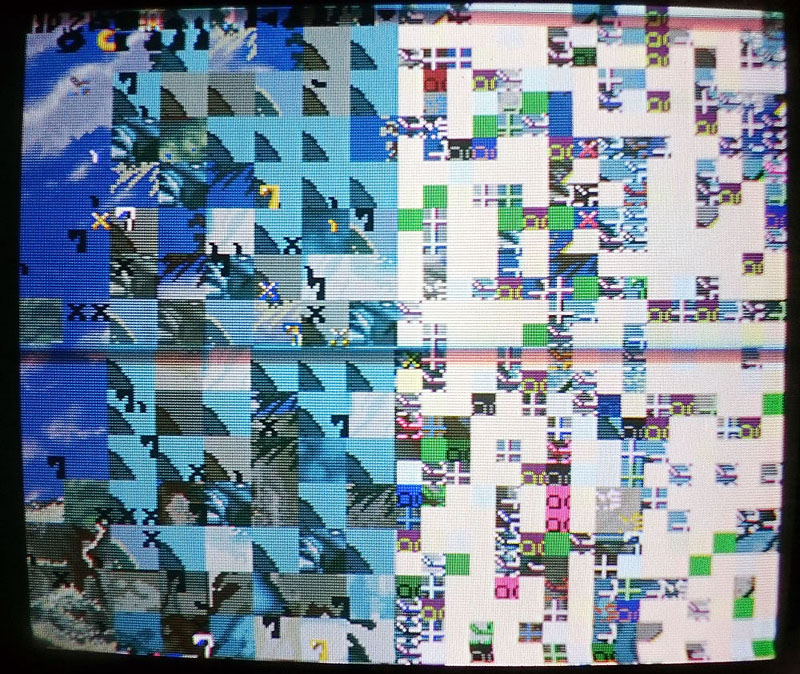
So I burned the PAL at location N5 from Robocop 2 and plugged it on my Ed Randy board and here is what I got:

edrandy4

Well, at that time I was thinking it was due to an incompatibility between Robocop 2 and Edward Randy PALs and I temporarily gave up, waiting to get a dump from a working Edward Randy to be sure…

Then Shoestring confirmed me Caveman Ninja and Robocop 2 PALs @ N5 were strictly identical. It leaded him to believe that perhaps they are all common to each other and maybe there is a different problem with my board, which pushed me to have a look back at my board for possible other faulty chips. And he did well…

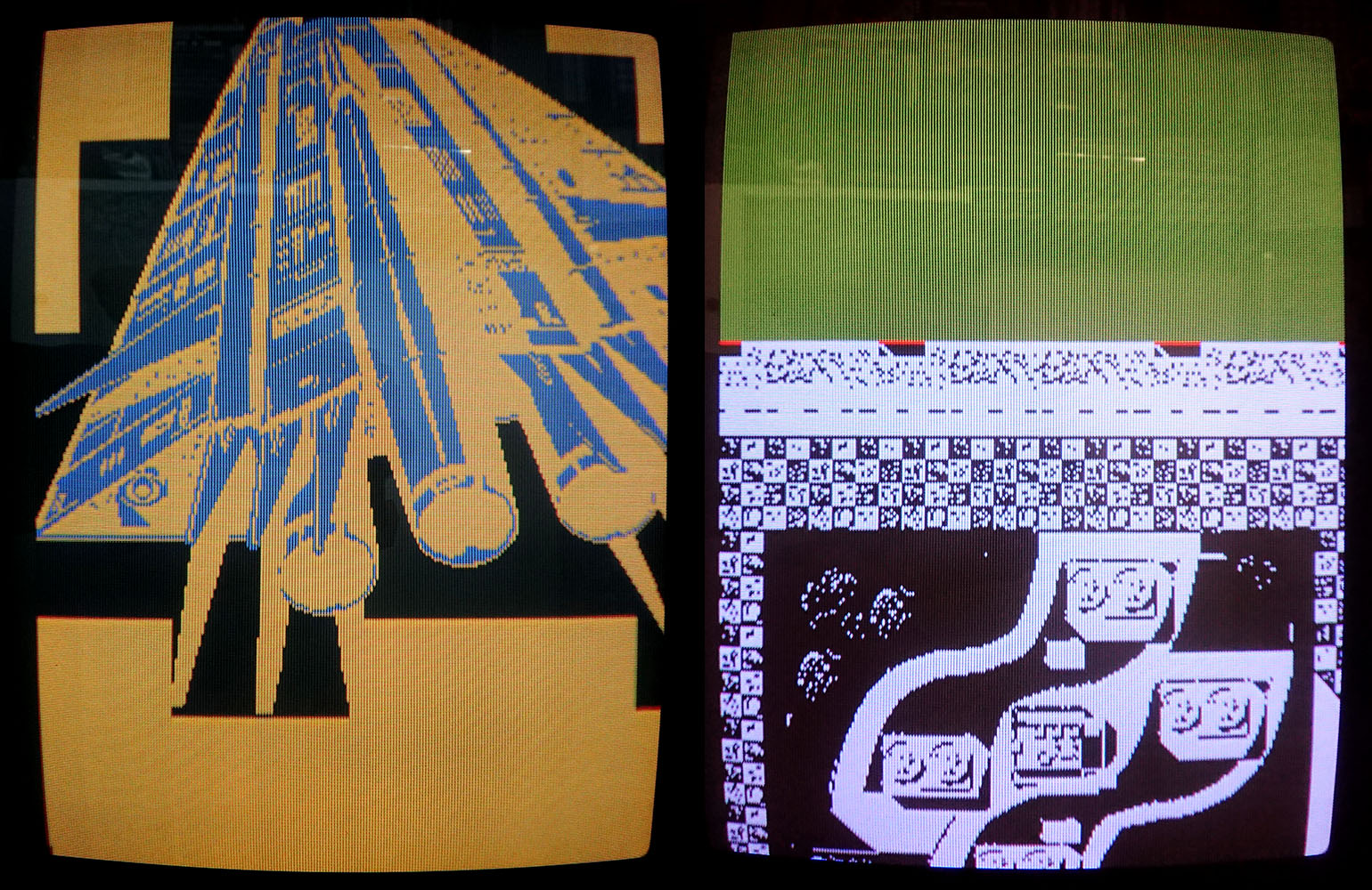
I started looking for other issues on the PCB and noticed that bending the board made the garbled graphics changing, even making them better looking at some point.
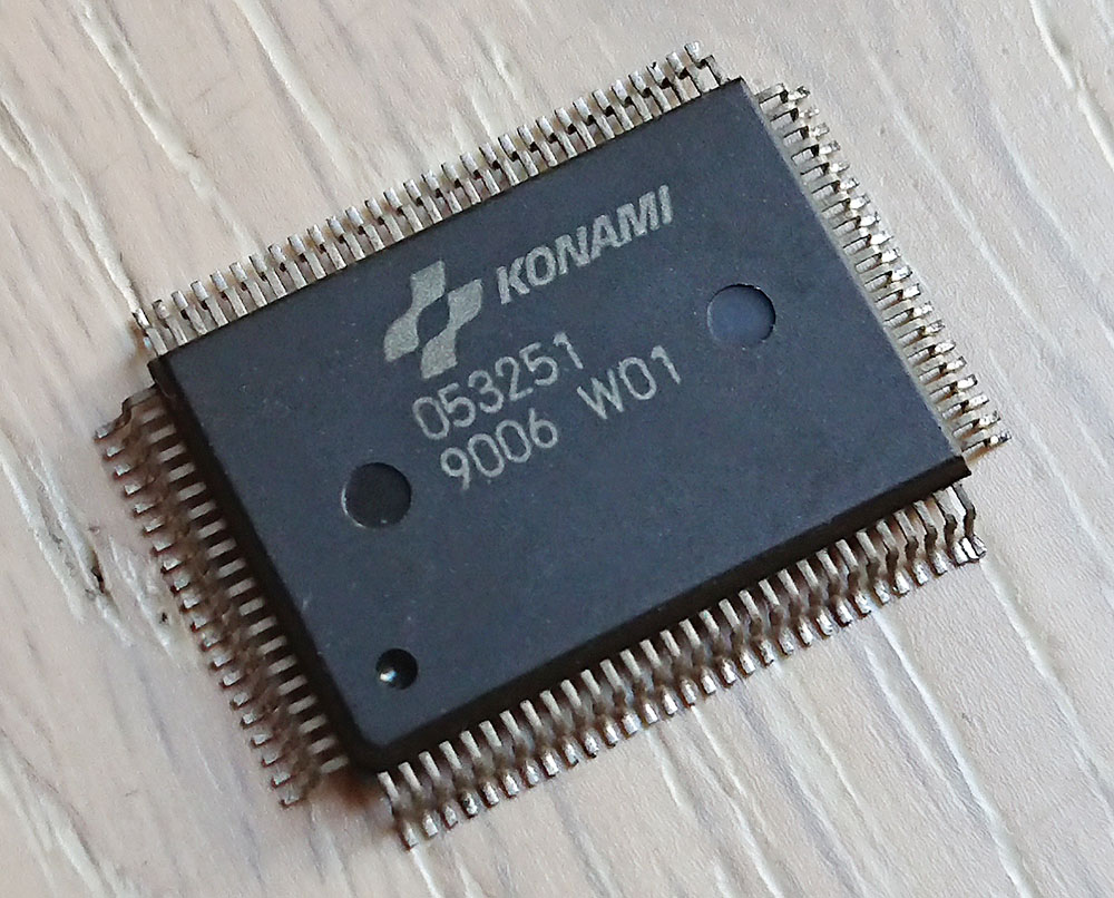
So I suspected the two SMC Data East customs labeled “55” having bad solder joints and reflowed the solder on them.

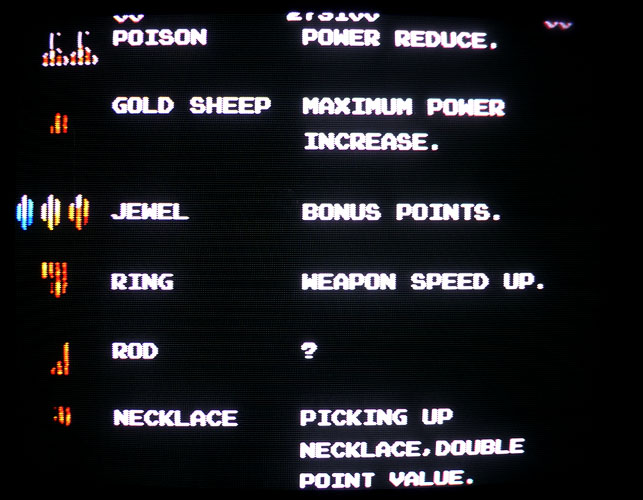
It then went way better. I had clean backgrounds in game, full intro with clean texts and pictures, title and Data East logo appearing (didn’t have all of that before) but no sprites in game. I noticed a square on the bottom-right corner that seemed containing garbled parts of sprites.

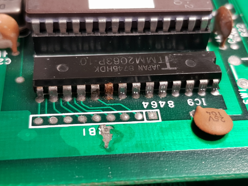
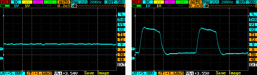
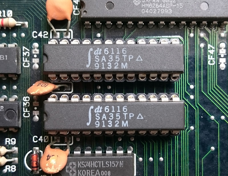
I then managed to find where the sprites part was located on the board and found two 6116 RAMs @ locations N9 and M9 that had suspicious signals on their data lines (pulsing but weakly and at low voltage). Piggybacking a known good working compatible RAM made parts of garbled sprites randomly appearing on screen.

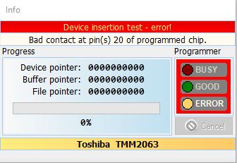
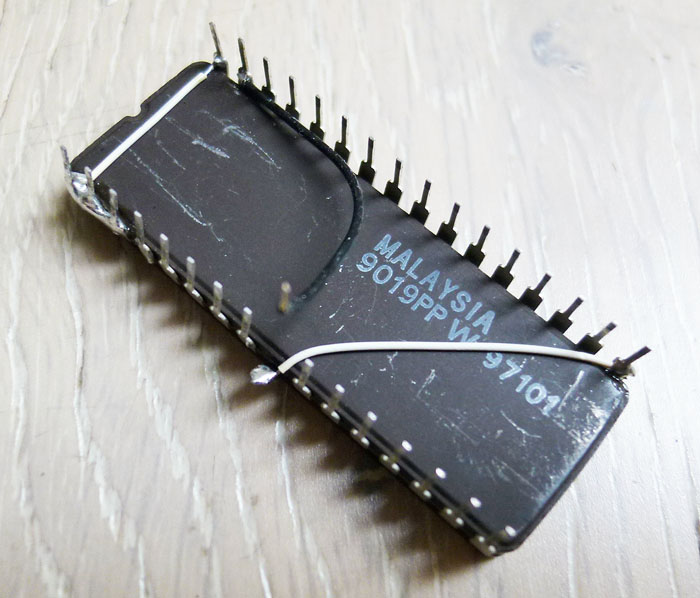
I then desoldered one of the two RAMs (at location N9). With no big surprise it was tested bad on my programmer. I soldered a socket and put a new RAM in place. There was still no sprites but the garbled square on the bottom-right corner was not there anymore. Data lines on the new RAM were looking pretty much better though with strong pulses at 5V. The RAM located at M9 still showed weak outputs so I replaced it with another good known RAM:

edrandy6

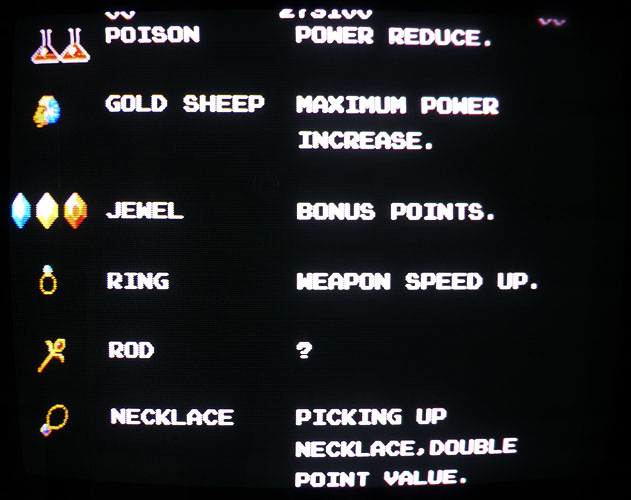
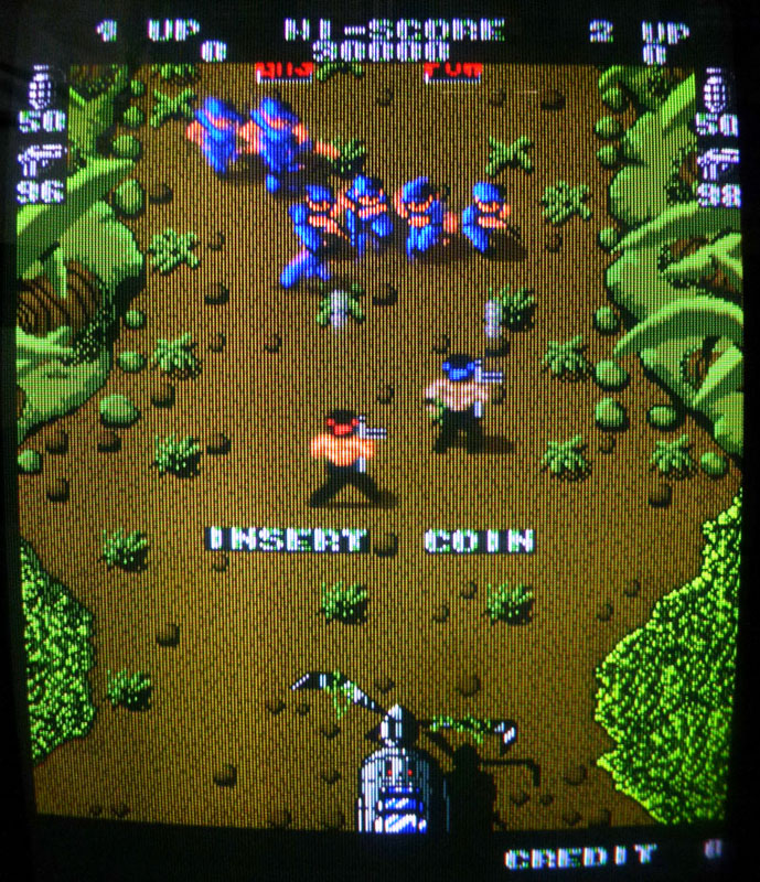
Then sprites magically appeared !

edrandy5

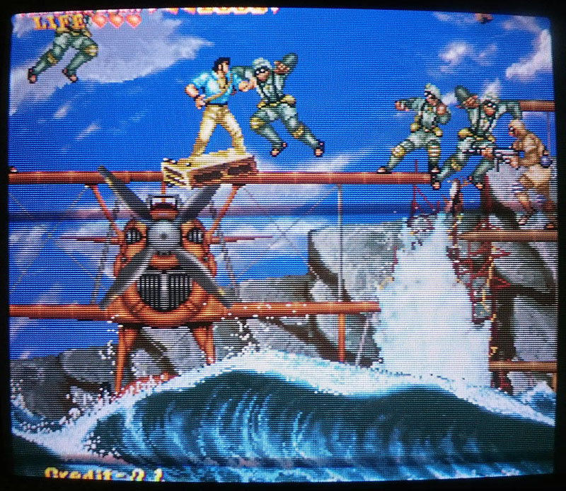
Only one thing was remaining: the voice generating chips (2x OKI M6295) were missing so I replaced them and got the sound fully working.

I played the game several times since that and it is working perfectly.