
Got this Vigilante PCB (by Irem) in a trade some years ago:

Board was dead, stuck on a purple static screen:
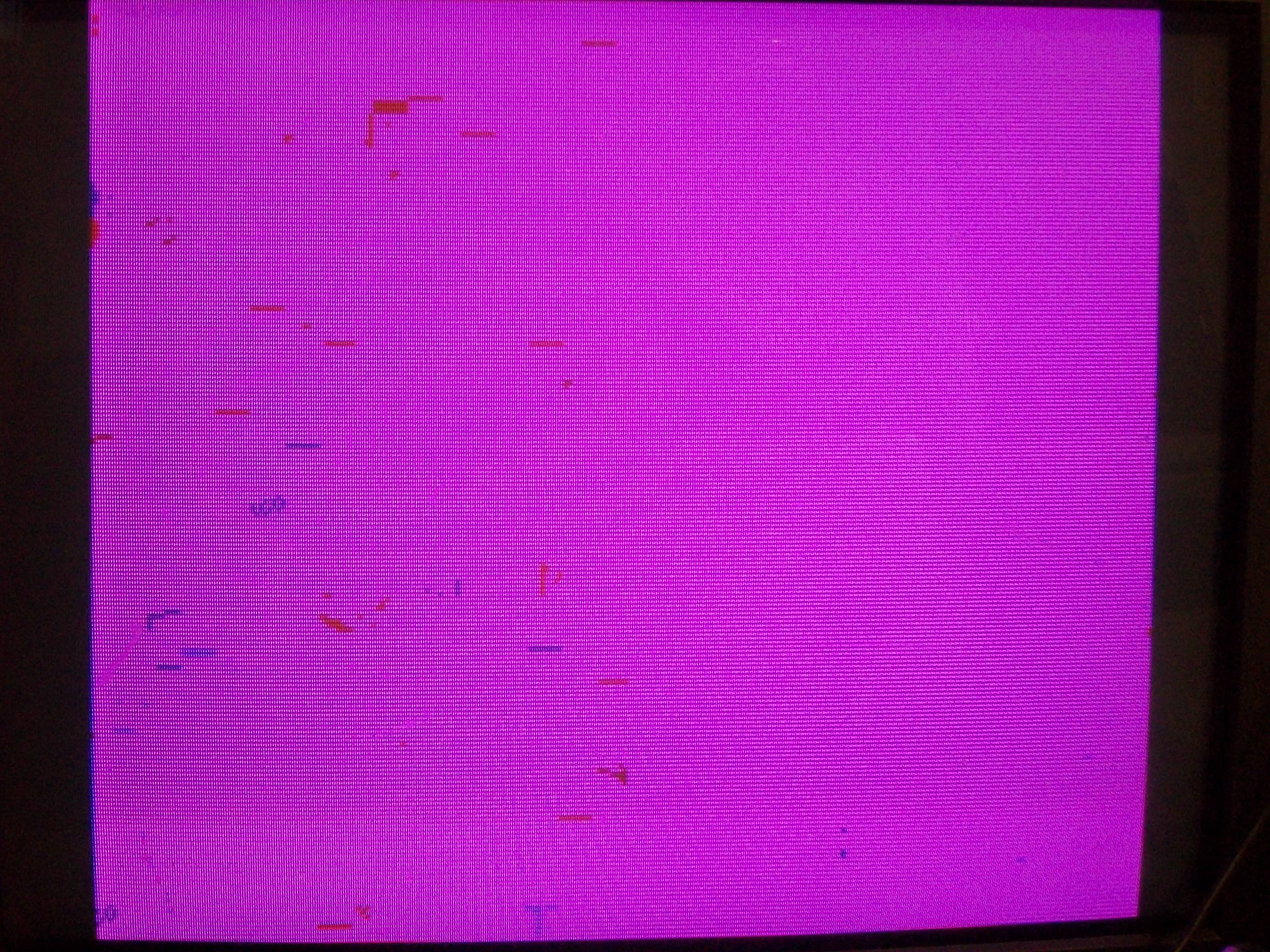
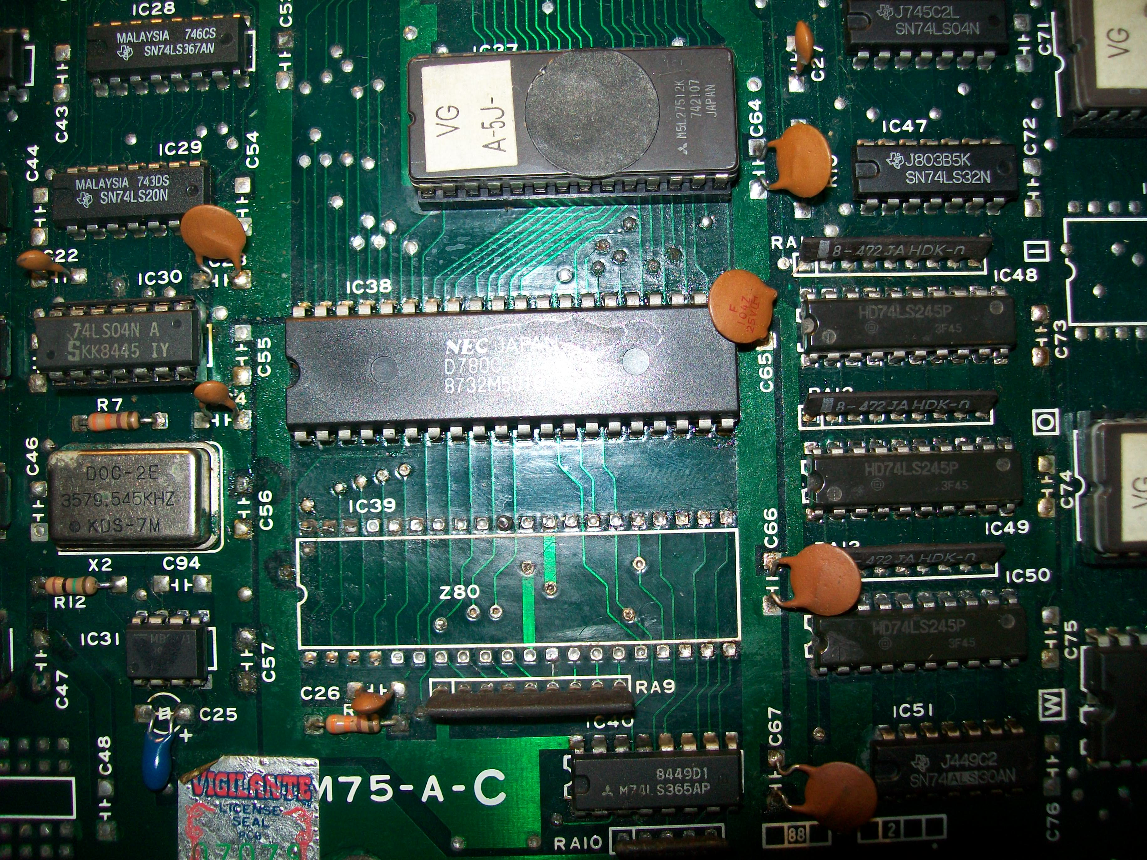
As usually I started my troubleshooting with a visual inspection and noticed severe corrosion in some areas, especially around the 3.579545 MHz oscillator:
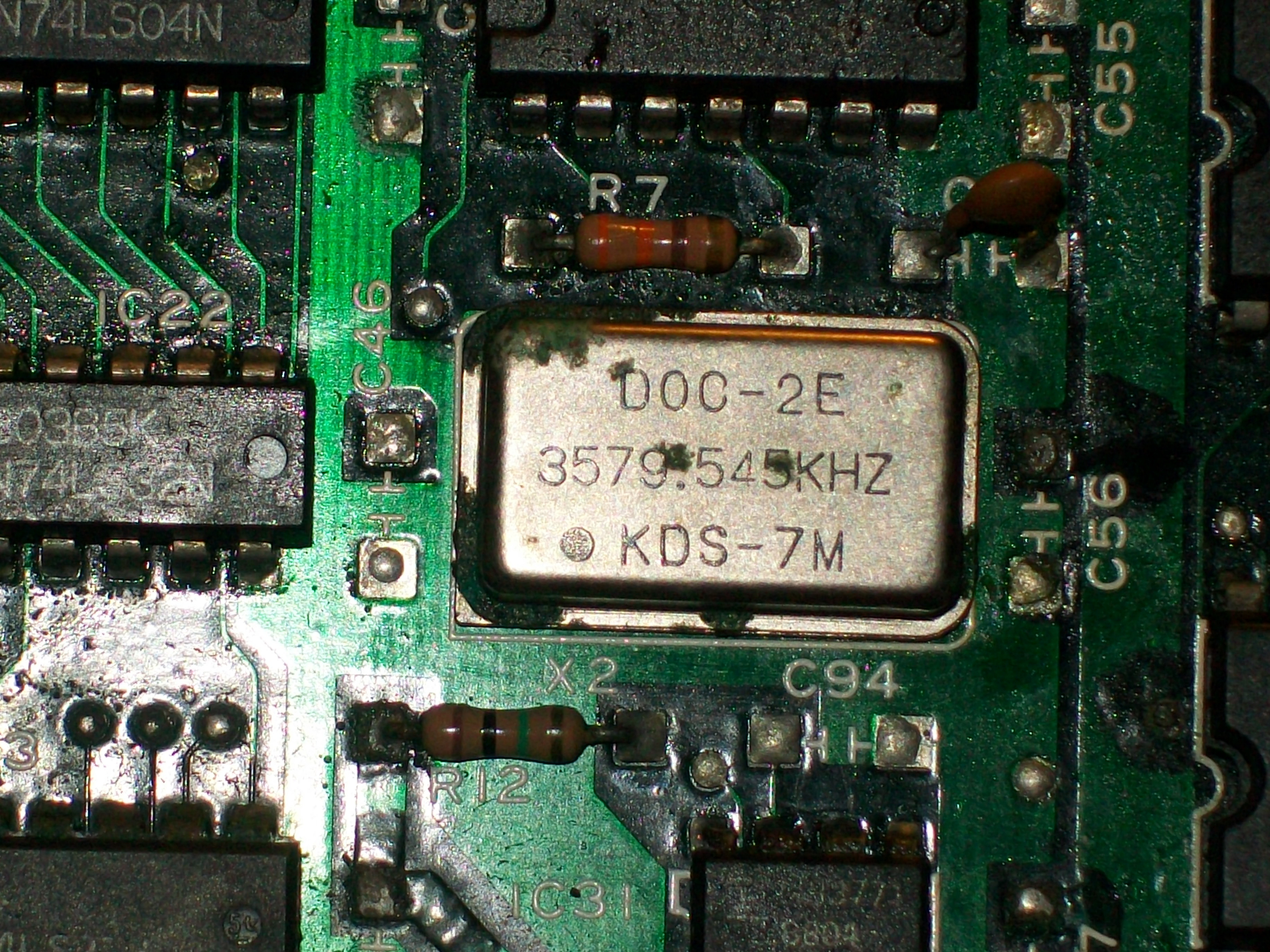
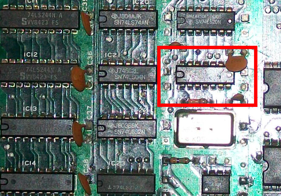
Analyzying the main Z80 CPU revealed no clock on pin 6.This signal was present on oscillator output but then was lost when routed to the inverter (a 74LS04 @IC30) :
Replacing the TTL restored clock on Z80 but board was still dead.Probing the /RESET pin 26 with an logic analyzer showed an unhealthy signal, there was no proper transition from LOW to HIGH but only some oscillations :

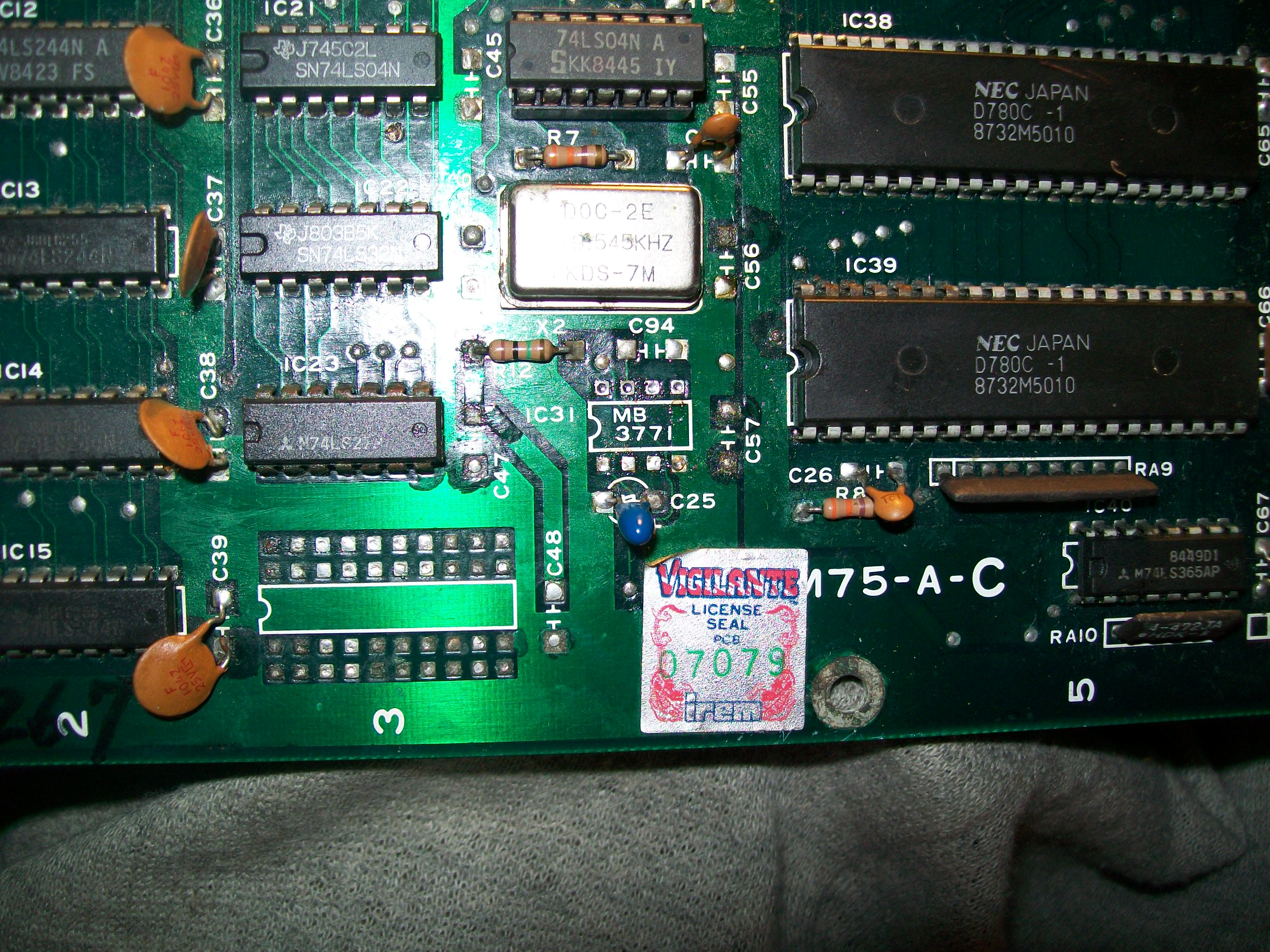
/RESET signal is generated by the MB3771 voltage monitor @IC31.I promptly replaced it:
In this way proper signal was restored:

But main Z80 was still inactive, data/address busses were silent as well as control lines.This lead me to think the CPU was faulty so I removed it:
Testing it in another board confirmed it was really bad.With a good CPU the board finally booted up but the sprites were mostly absent, I could see only some parts of them randomly flying over the screen:
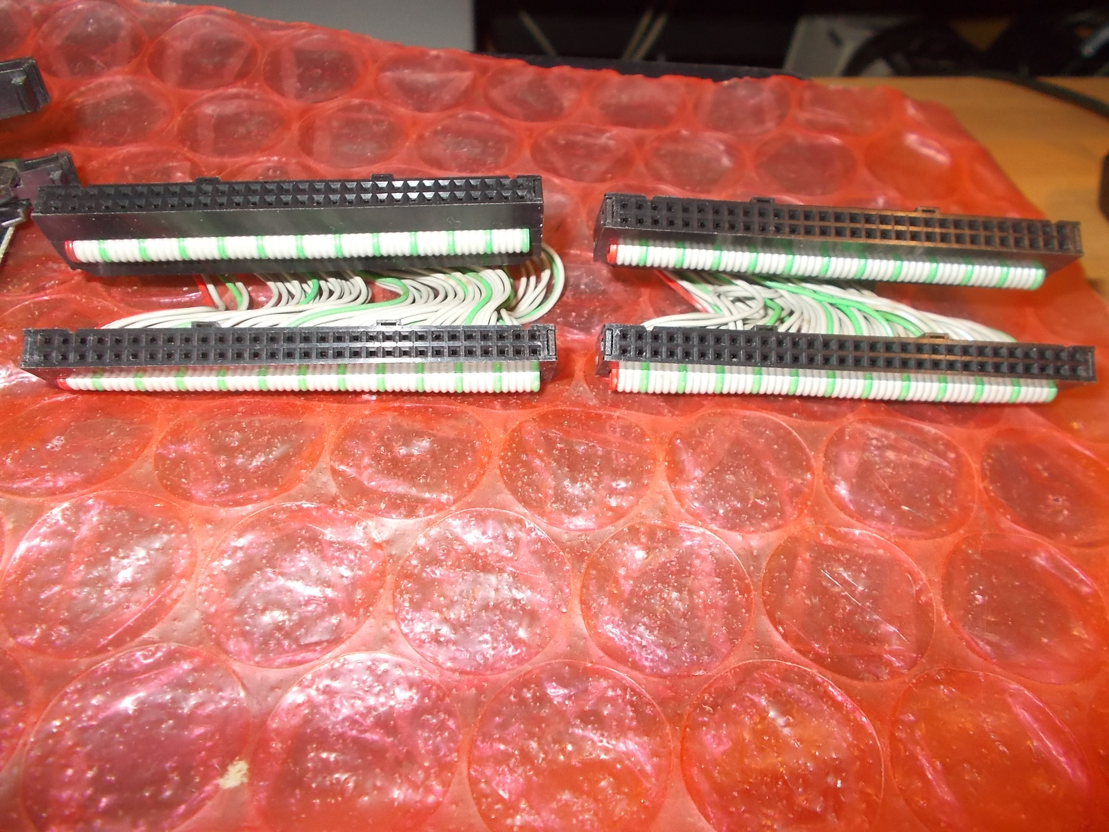
After some time spent to check different things I pinpointed the fault in a bad interconnect ribbon cable.For safety I replaced both of them:
Board fully working again and a quite enjoyable game added to my collection.
The repair was accomplished but, as always I do, I visually inspected the board looking for some candidate parts for a reproduction and I spotted two possible ones.The first is marked ‘8M472J221J’ (‘RGLD8M472J221J’ on manual parts list)
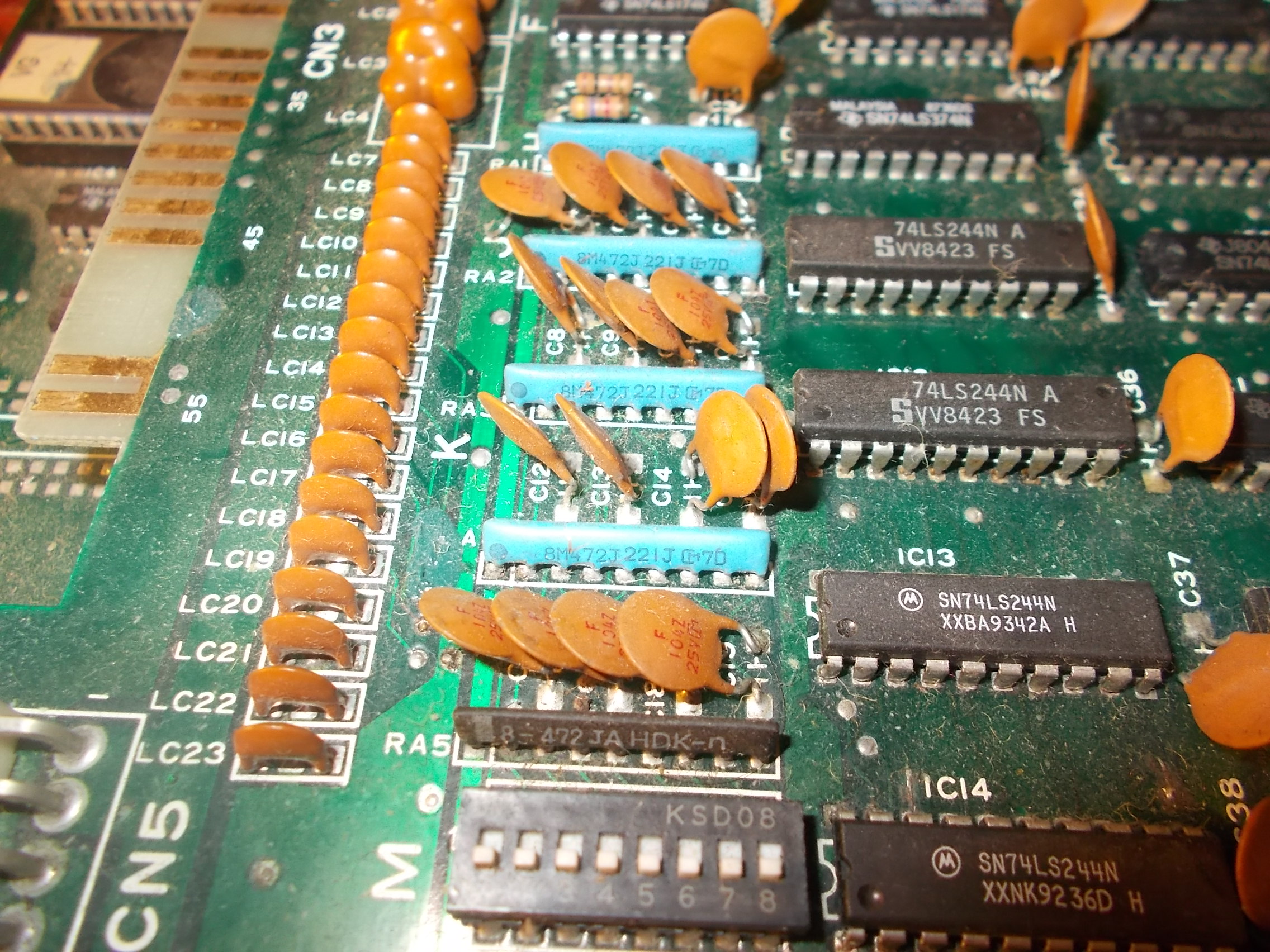
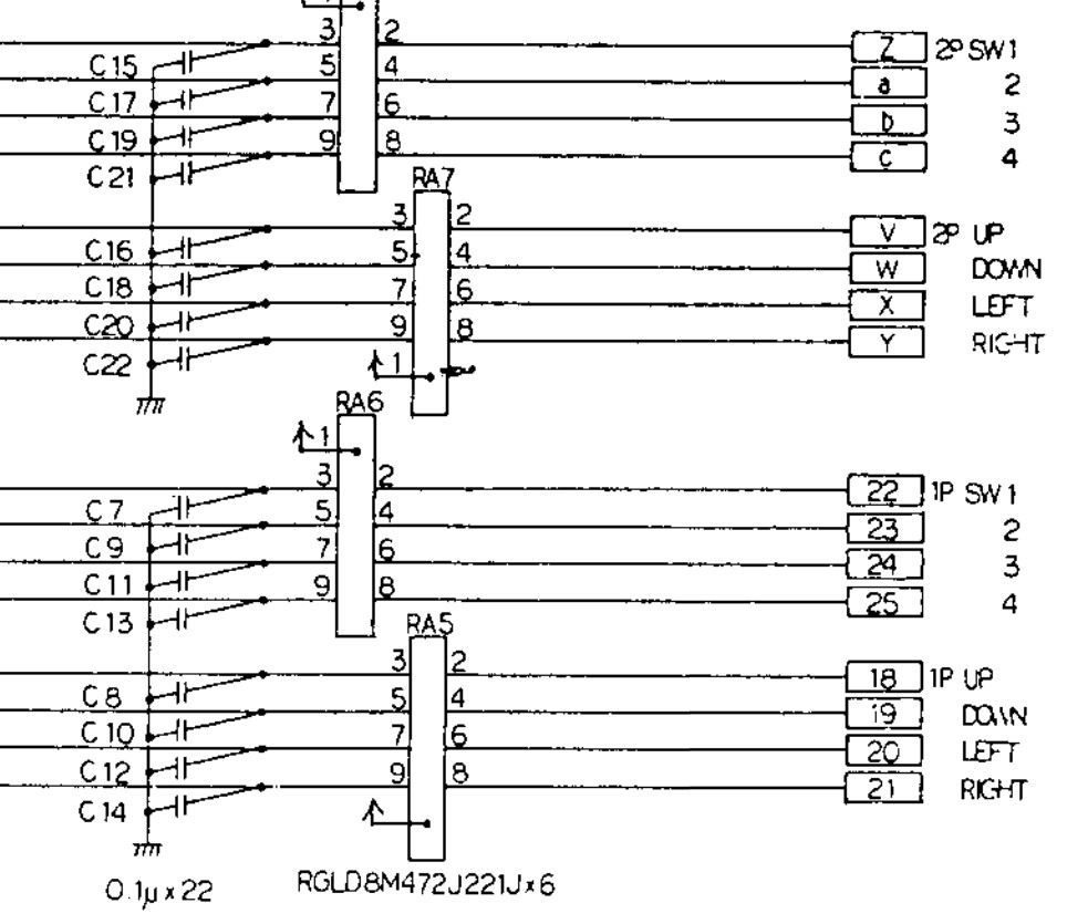
It’s nothing more than a custom resistor network used for inputs, you can find it also on other Irem hardware like M72, M92 and M107.Here’s snippet from R-Type schematics:
I reproduced it this way :

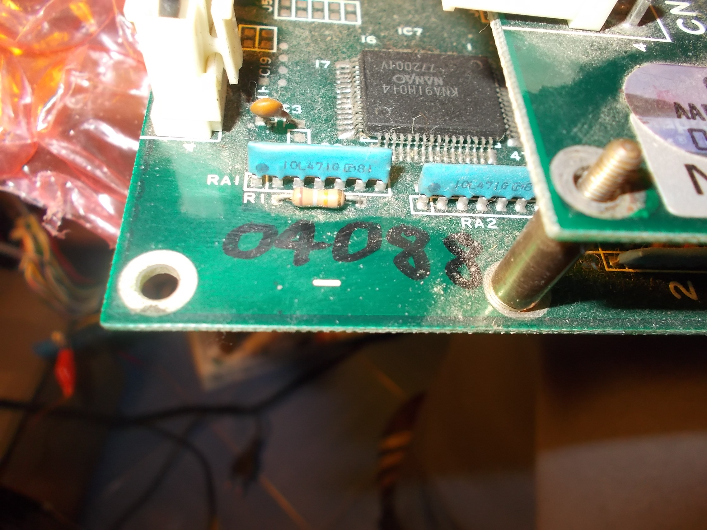
The latter, marked ’10L471G’ (‘RGSD10L471G’ on manual parts list) is interesting since it’s a R2R resistor ladder used to convert to analog the 5 palette digital bits outputted by the surface mounted ‘KNA91H014’ custom.You will find always three of them (one for each RGB color) coupled to one custom.
Its implementation on schematics:

From my experience and other references too the original part is not really reliable (it will crack or burn) so I reproduced it as well:
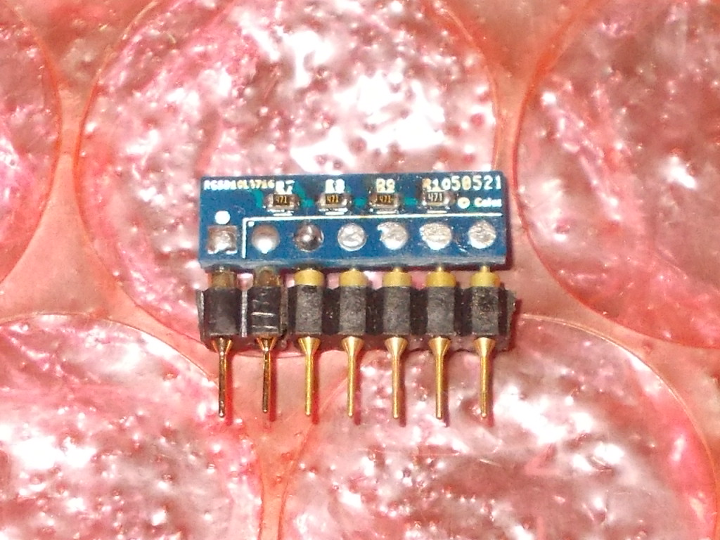
Testing both reproductions on the repaired Vigilante PCB:
Sorry, the comment form is closed at this time.