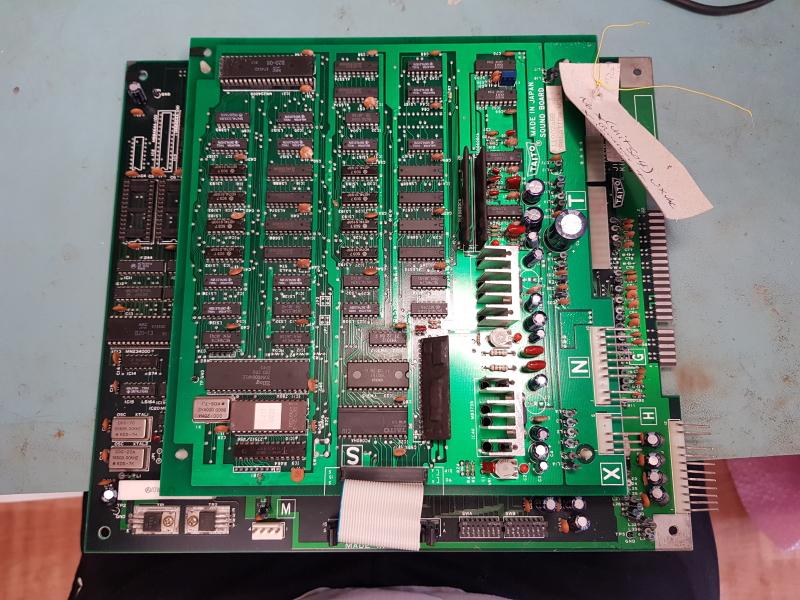
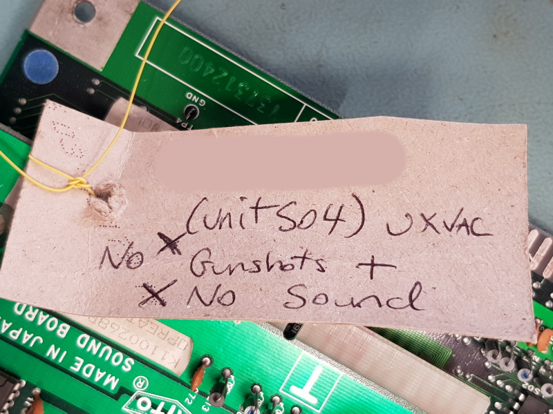
Another few Operation Wolf boards in at the moment. This one is from Unit504.
There is a nice little tag on this telling me the faults which really helps me keep all these boards together and where to start looking.
First job was to look into the gun shot register issue.
I did a quick test and could see the screen flash when the trigger was pulled so I knew that wasnt the fault
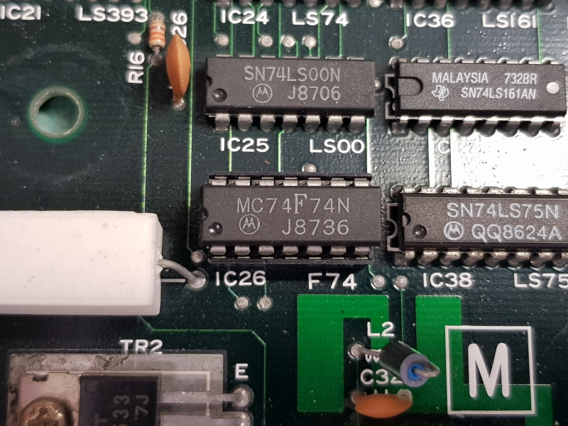
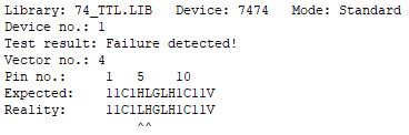
Following the circuit I come to the 74F74 IC which is used to latch the gun co-ordinates.
I normally wouldn’t start looking at this part but it was already socketed so decided to pull the chip and test it. It failed an out of circuit test.
I replaced this with a 74ALS74 and it seems to be be fine.
Now all the gun shots register as expected.
Next onto the sound.
None of the sounds were working at all and I didnt believe that all the seperate circuits for making sounds would be dead so looked a bit closer at the CPU side of things.
First off I checked the ROM and it dumped out fine.
Next the RAM. An inspection of the RAM showed signs of corrosion
I removed and tested it and thankfully it failed
Looks like that corroded pin has broken contact somewhere. Anyway, replacing the RAM brought all the sound back to life and completed this repair.
Got this board set from Paulcan69 to have a look at.
The faults reported were gun shots do not register & there was no sound.
I was told before hand that the gun issue seems to be a very common problem so I focused my attention on that first.
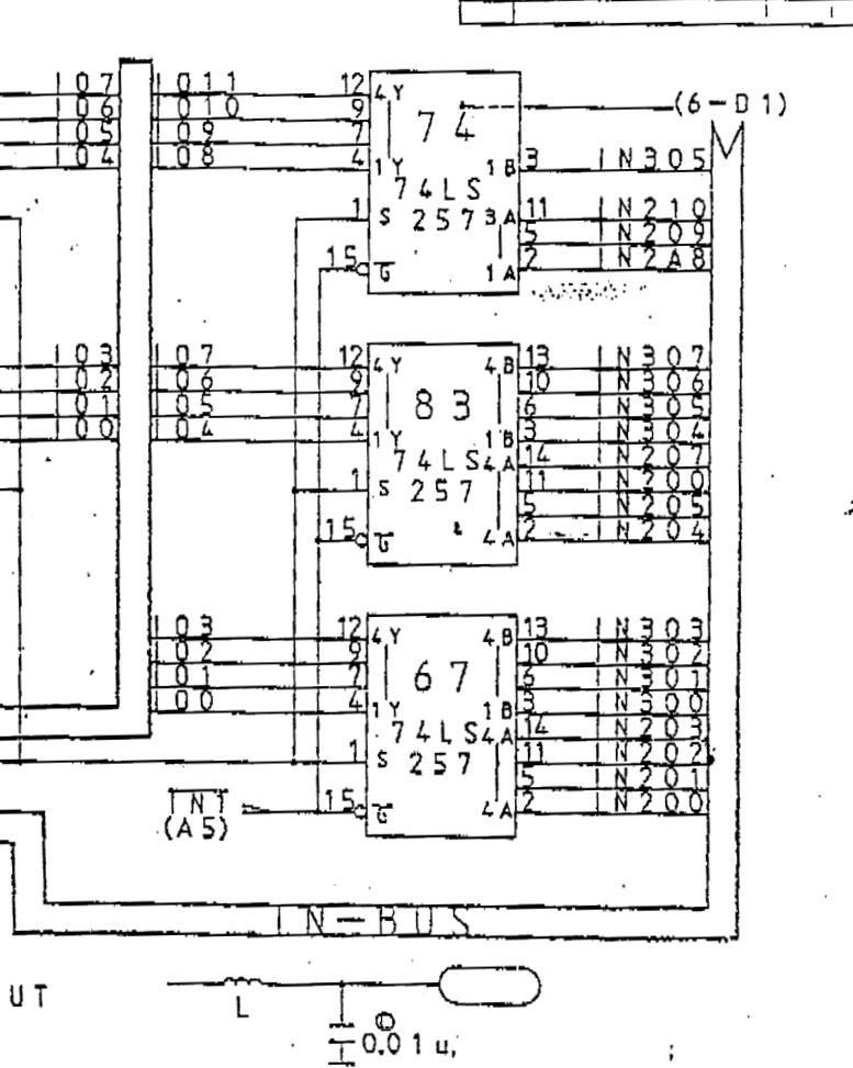
The input from the gun comes in from the sound PCB and passed straight down to the main PCB.
First I checked the signal from the gun was actually reaching where it should do
I confirmed that on a trigger press in game that the signal reaches pin 3 of the 74F74 at IC26 and also that pin 5 output latched.
Using the scope I could also confirm the operation of the 74LS75 at IC38.
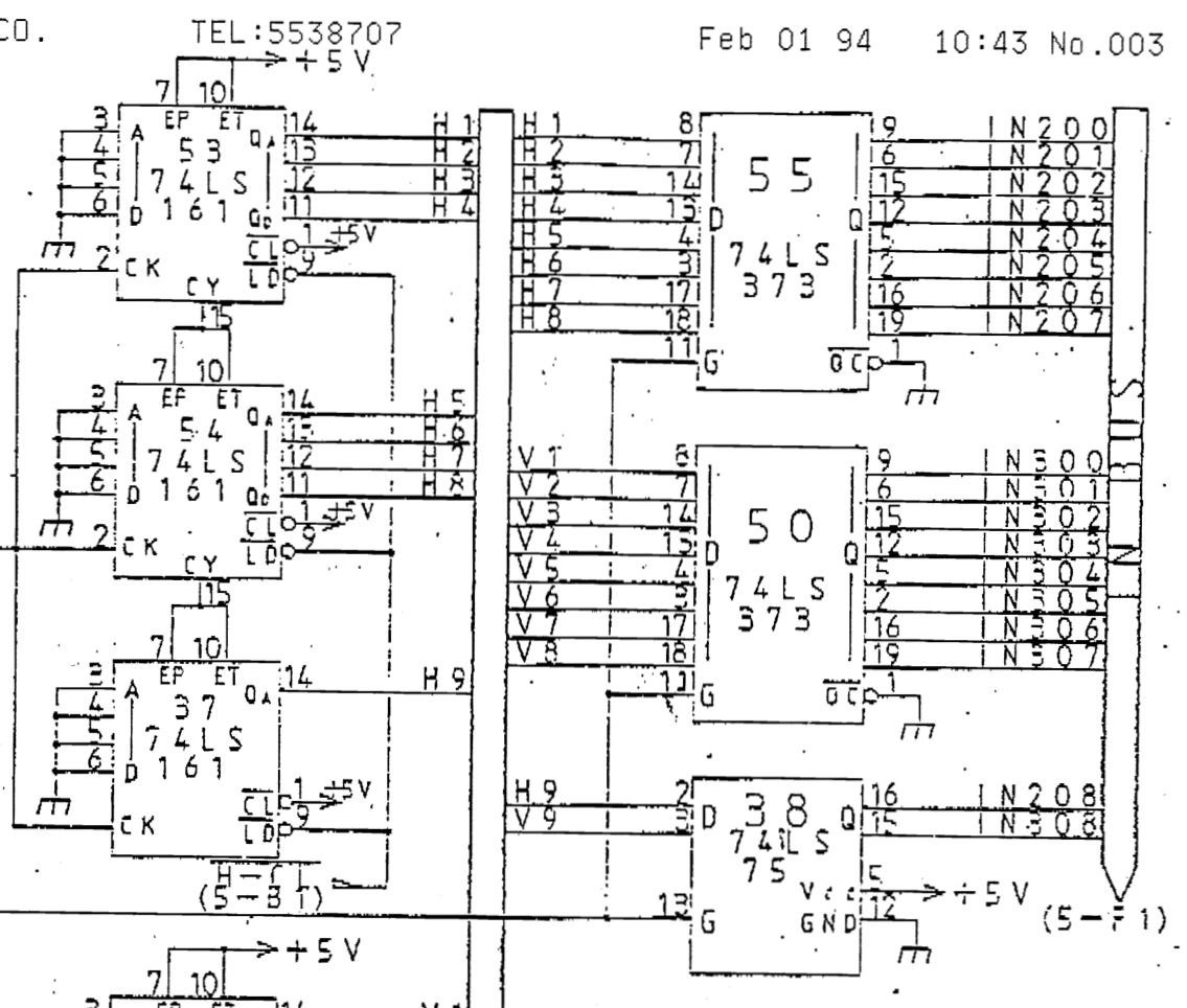
The current XY screen draw position is tracked by a set of 74LS161 counters and fed into 74LS373 transparent latches.
When the trigger is pressed the the 74LS373’s are latched and the current XY values are sent to 3 x 74LS257 data selectors.
These selectors are read by the main CPU from address $3A0000 – $3A0001.
Using the scope syncing on pin 15 of the 74LS257’s I confirmed that some of the outputs on these were always logic HIGH.
I ended up replacing IC67 & IC83 which fixed the gun problem.
Next was the sound issue.
This one had no sound at all.
All the signals looked OK from the CPU side but nothing was ever being asked to play a sound.
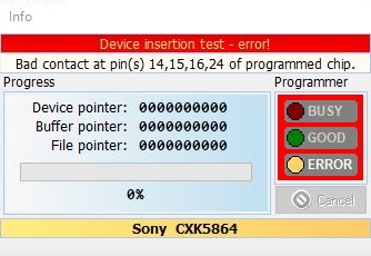
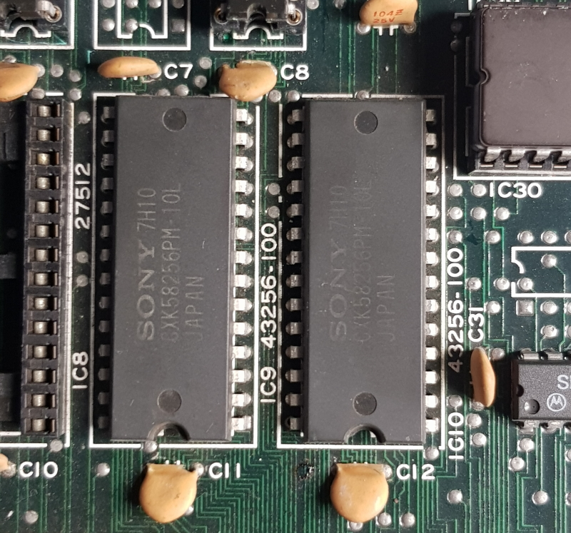
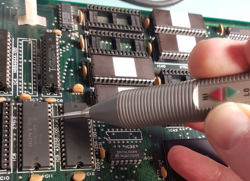
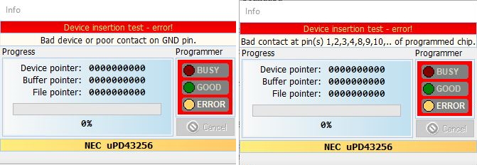
Given the fact that the board uses the Sony brand RAM I just went right ahead and removed it as they have been very unreliable in recent times.
It failed in an out of circuit test using my programmer
Now the music was back but the samples did not.
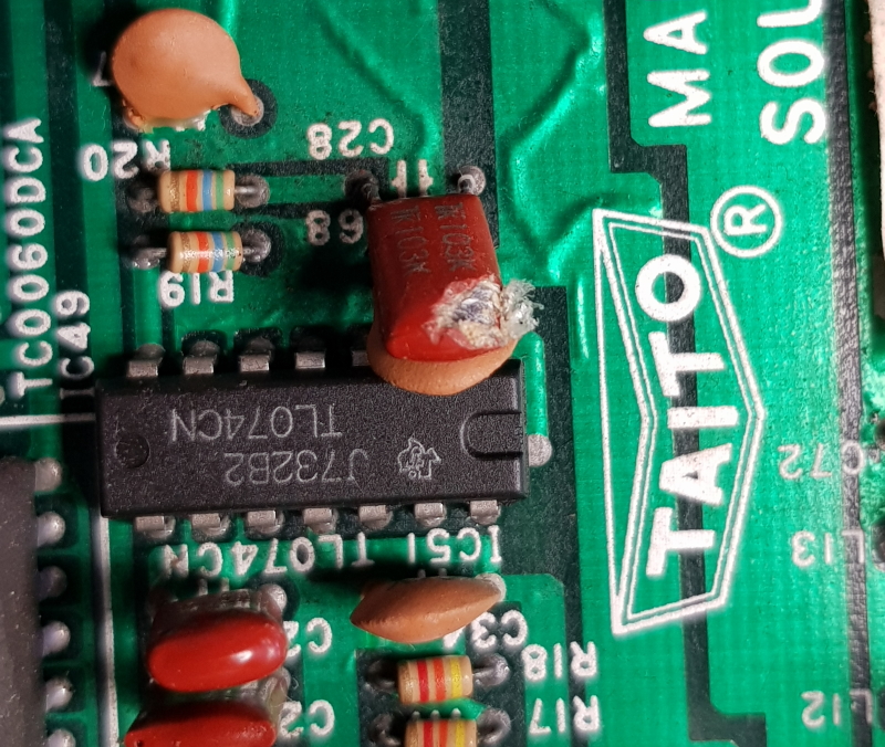
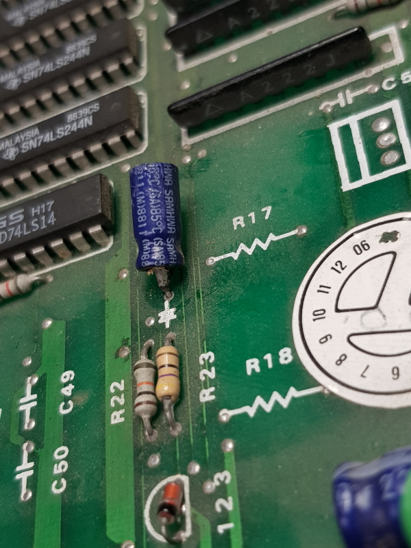
I already had a pretty good grasp on how the sound worked from my previous repair so started checking the same areas as before but didn’t really find anything but then I spotted this
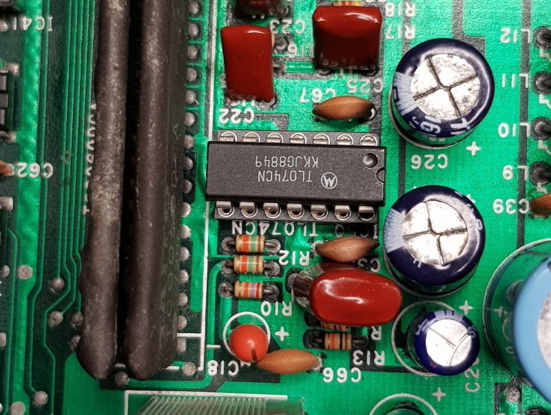
This is part of the feedback circuit for the op-amp. Replacing this gave me some samples back but they cut out before they finished playing and some didn’t play at all
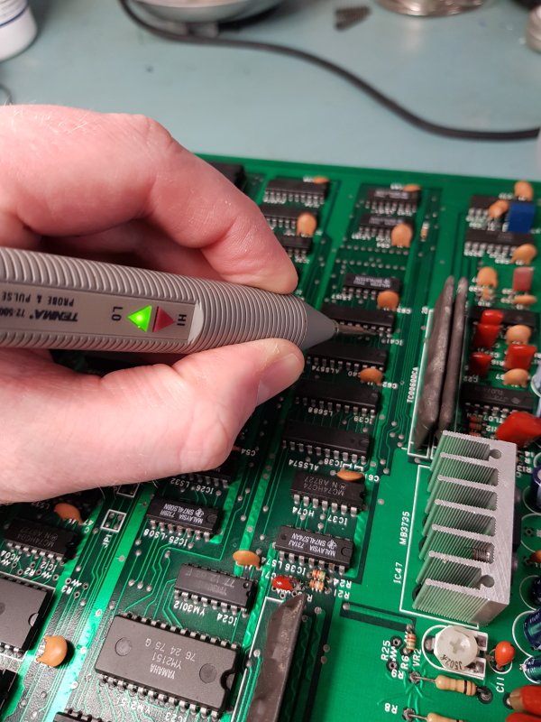
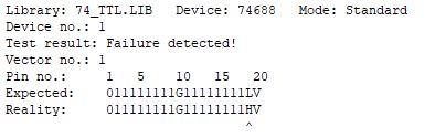
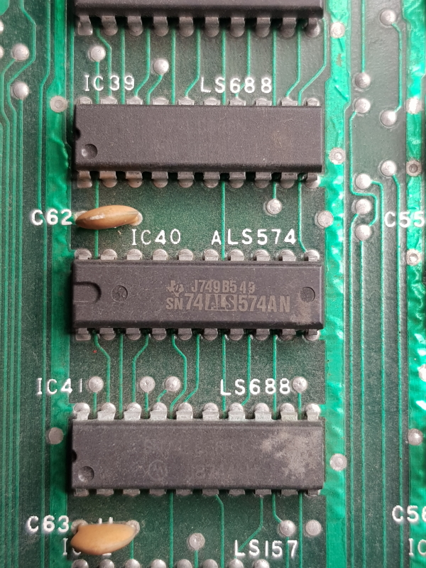
I knew exactly where to look for this and quickly found the 74LS688 at location IC41 with its output stuck LOW.
I removed and tested which obviously failed
I initially thought I would have to put this repair on hold as I needed to order some 74LS688’s but turned out I had to wait less than 24hrs for Farnell to deliver.
With the new chip fitted I had my sounds playing for the right duration but all the samples on the A channel were still missing altogether.
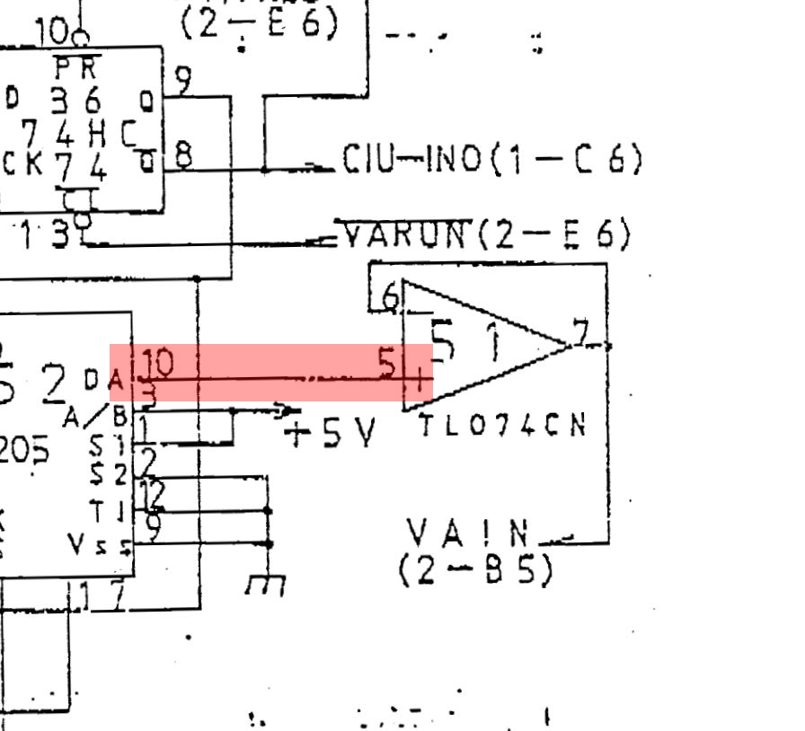
Using the scope I traced the sound to the output of the M5M5205 ADPCM Speech Synthesis LSI at IC50 (schematics incorrectly refer to it as IC51)
I could see the signal going into the op-amp but nothing was coming out so I replaced it.
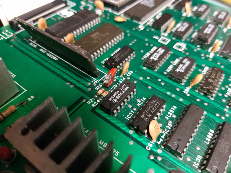
I now had an output from the op-amp but still no sound. Tracing this through on the PCB I came across another damaged capacitor (no idea how I missed this one as well)
Replacing this brought all the sound back and that’s another one complete.
I recently got two Operation Wolf boards from Muddymusic to fix.
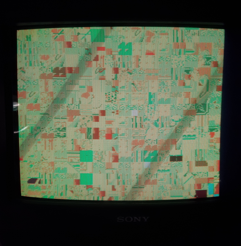
This board was not booting at all and I got a screen full of flickering garbage
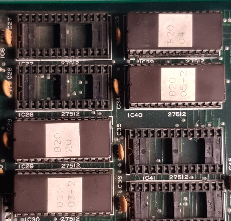
I removed all four of the 27C512 program EPROM’s and verified they were good. All of them matched the “World, Set 1” version in MAME.
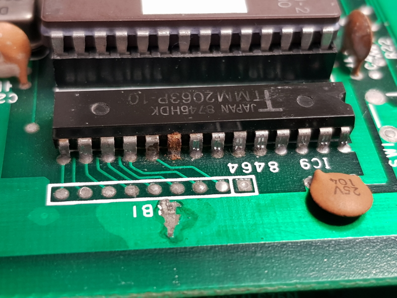
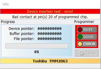
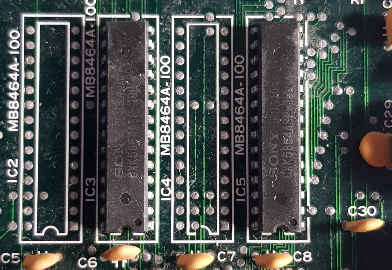
I confirmed continuity between all the address, data and control pins of both EPROM’s and RAM was present and correct and it was so I opted to remove the two TMM2063 work RAM chips and test those
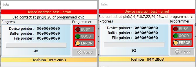
As you can see both failed. I replaced them and tested but there was no change.
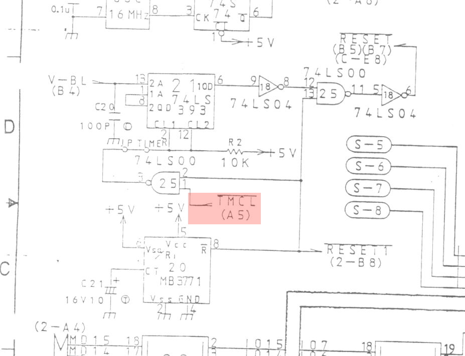
Next I started looking at the reset circuit.
Here is the main reset circuit taken from the schematics
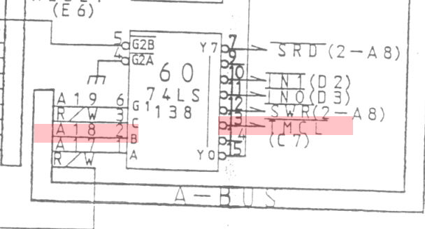
Using the logic probe I found that signal “/TMCL” (timer clear) was floating. Shifting focus to grid A5 on the schematics we see that this signal comes from pin 13 on the 74LS138 at location IC60.
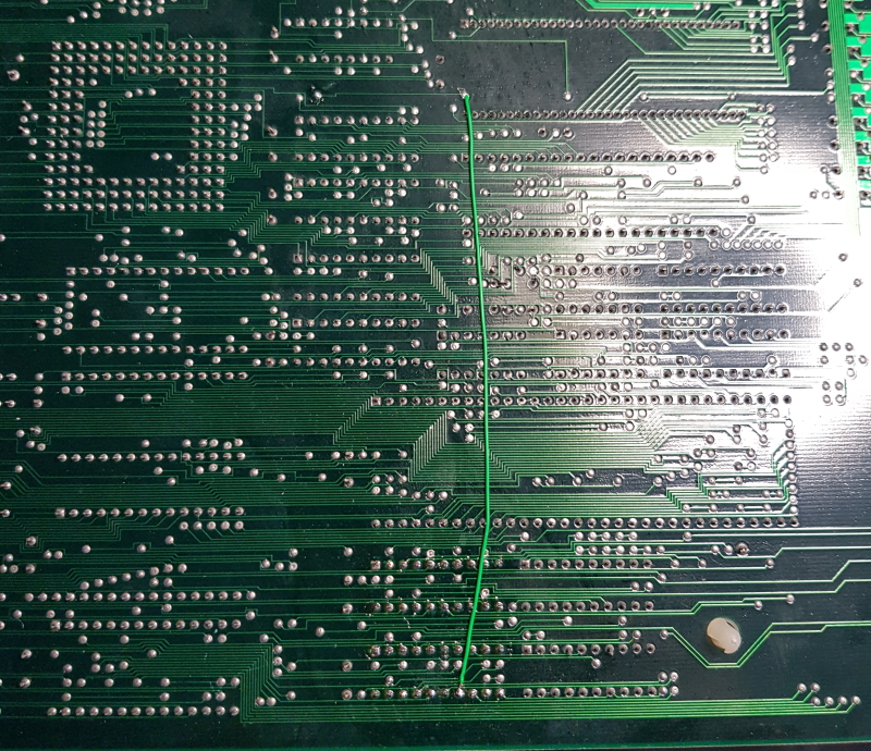
Further probing found that the A18 signal on pin 2 was also dead. This signal is the buffered MA18 (address bus pin 18) and comes from the 74LS244 at location 65. Checking the signal on the LS244 revealed that it was present so there was a break in the trace some where.
I couldn’t see anything obvious so I patched it with some Kynar wire
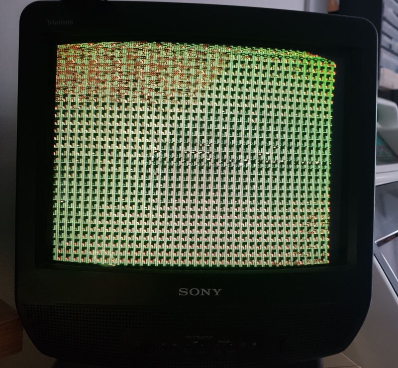
No on boot up I get no more resetting buyt the screen is full of garbage still
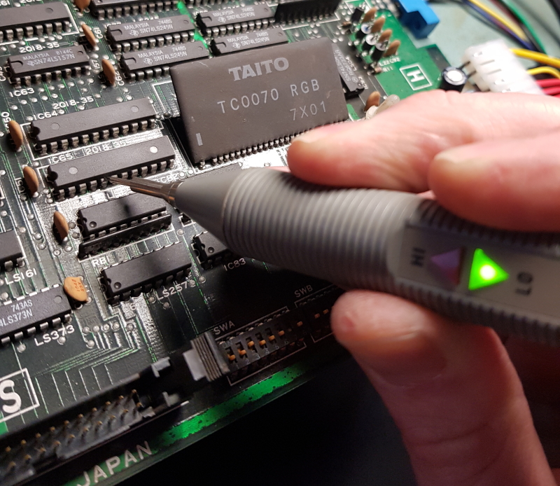
Next I started looking at the custom PC080 tilemap generators, more specifically the RAM connected to it
Checking both of these with the probe showed me there was no activity on most of these pins and some others were stuck high
I removed both of them and checked them, obviously both failed
Replacing both of these now gives me something to see.
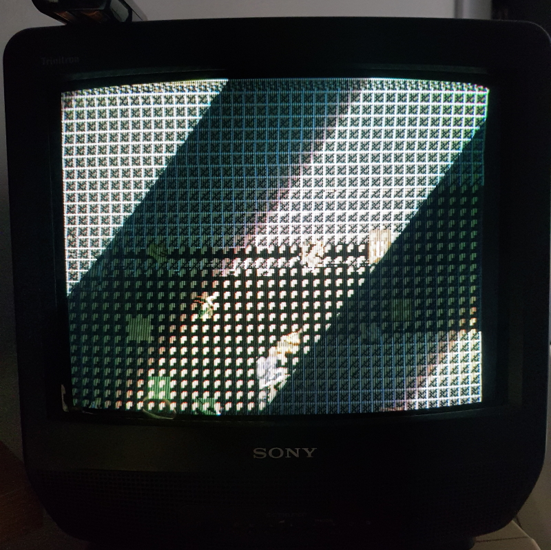
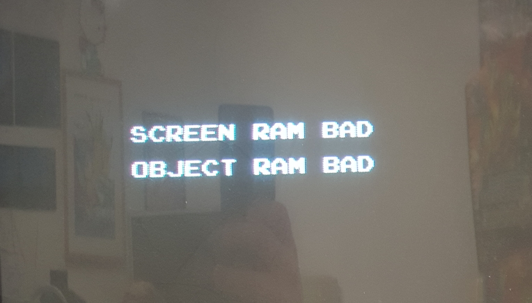
In test mode I get this
I looked into this fault for a good hour or so before I decided the RAM I fitted was too slow. Swapping for a faster RAM type fixed both of these issues.
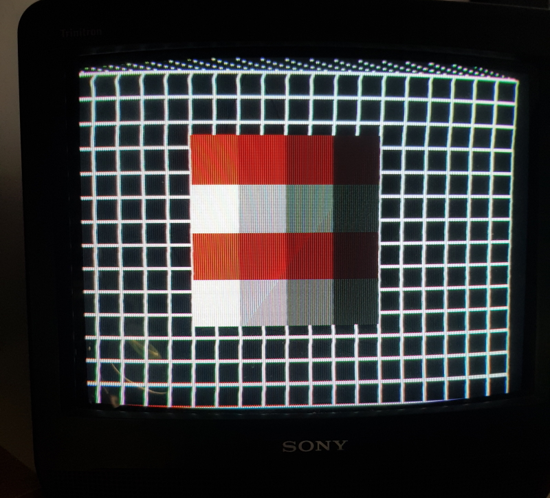
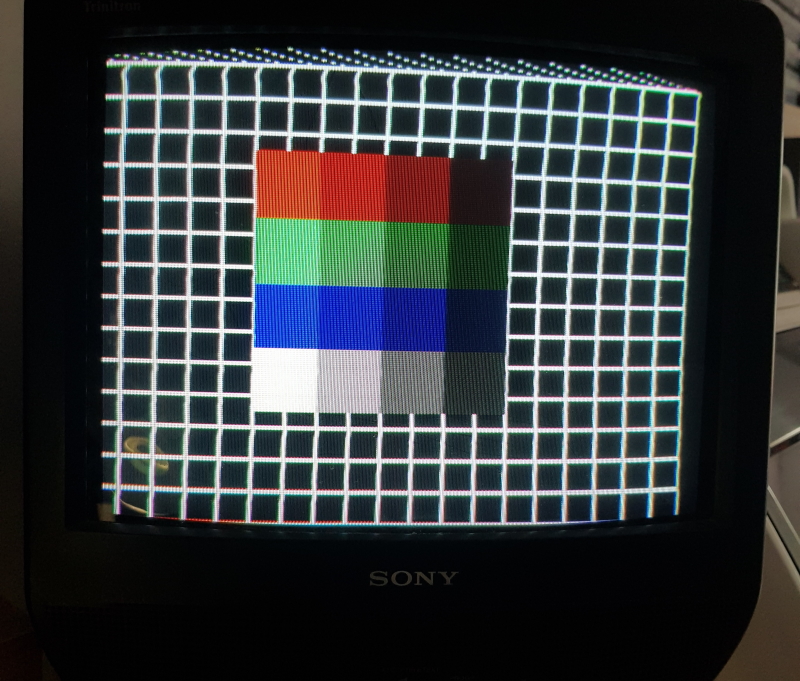
Now the board would successfully pass the self test in the test mode I could see that I had an issue with colours.
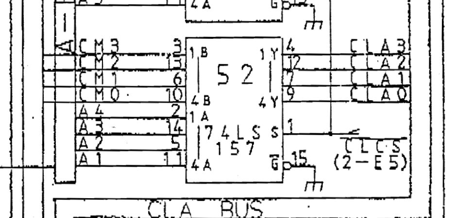
I started off probing the colour RAM at locations IC64 & IC65 and quickly found bit 4 of the address pins stuck low
Using the schematics I could easily trace this back to a 74LS157 at IC52
Replacing this gave me my colours back
Now onto the sound board.
The good news is all the music was present and correct. The bad new was all the voice samples were not.
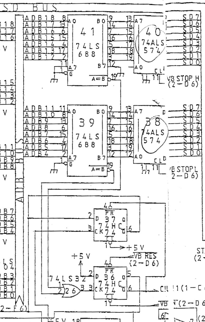
Again, using the schematics I see that ultimately the addressing for the Maskrom at IC21 gets set by a bunch of 4-bit counters at IC27-IC30.
Probing these I found that the UP counter wasn’t pulsing at all
Checking the 74LS04 at IC32 revealed this inverter was bad so I replaced it and sound was restored but the sounds just carried on playing one after the other (never got a video of this).
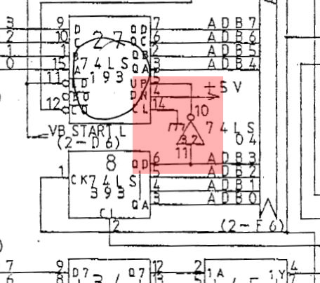
The Z80 sets the start and stop data by writing values to address $C002 & $C003 respectively which gets latched by a couple of 74ALS574’s and fed into the B side of a 74LS688 comparator
Using the MAME debugger I could see that the data being written to the 74LS574’s was correct but probing the /A=B output pin 19 of the comparators showed that these were either never matching or they weren’t working.
I couldnt find issues up stream of these so I desoldered them and replaced them with pulls from another board as I don’t have any spares.
I now have working sounds and fully working board set ready to return.
A few updates.
*Small bug fix when loading larger files so they now load.
*Removed a couple of the more obscure routines as I wasn’t happy with them.
*Now, if the loaded file is an uneven size it will offer to pad the file for you. Minimum size for this is 0x400.
*Fixed a bug with bit manipulation when saving/loading settings
PCB Repair LogsComments Off on Double Dragon II – The Revenge repair log #2
Jan252020
This board is a bootleg board but seems to follow the original fairly accurately.
On initial boot up this didn’t do a great deal but then other times it actually started up with various errors.
A fault like this always makes me look at the reset circuit.
This board uses a 6809 as the main CPU and a Z80 as a sub CPU.
The reset pin for the 6809 is pin 37 and using the scope I could see that most of the time it didn’t do what a reset should do.
Tracing it all back I came to this
The reset circuit on this is as simple as it gets really with a capacitor, resistor and diode.
I removed and replaced the capacitor and now the game boots up every time.
Now, although the game booted it appeared to crash when entering attract mode or starting a game with this fault
I remembered Bryan McPhail had the very same issue some time ago and he mentions that the sub CPU needed to be running.
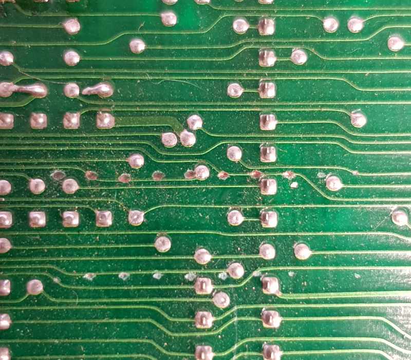
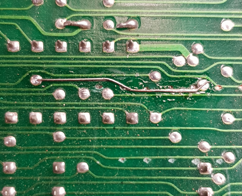
Checking the ROM for the sub CPU I found pin 1 (A15) was dead. Further inspection of the solder side of the PCB I found this
I patched this up as neat as I could and covered it using an overcoat pen
Now the issue was fixed
Last thing to do was deal with the sound.
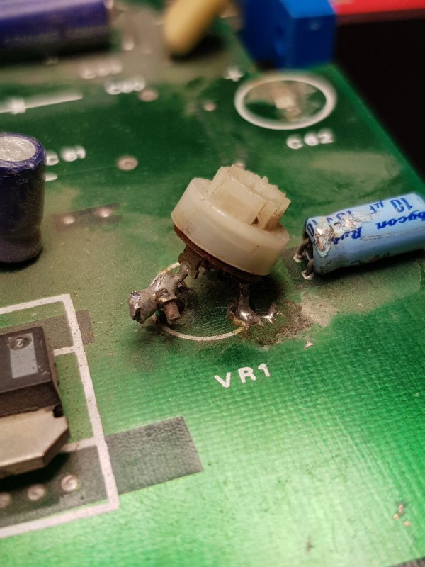
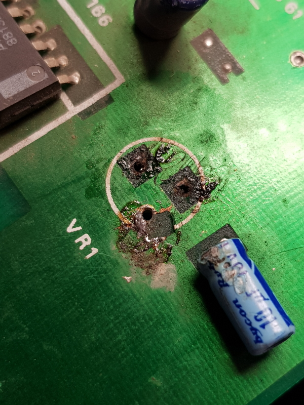
My initial inspection of the PCB showed the volume pot had been messed with
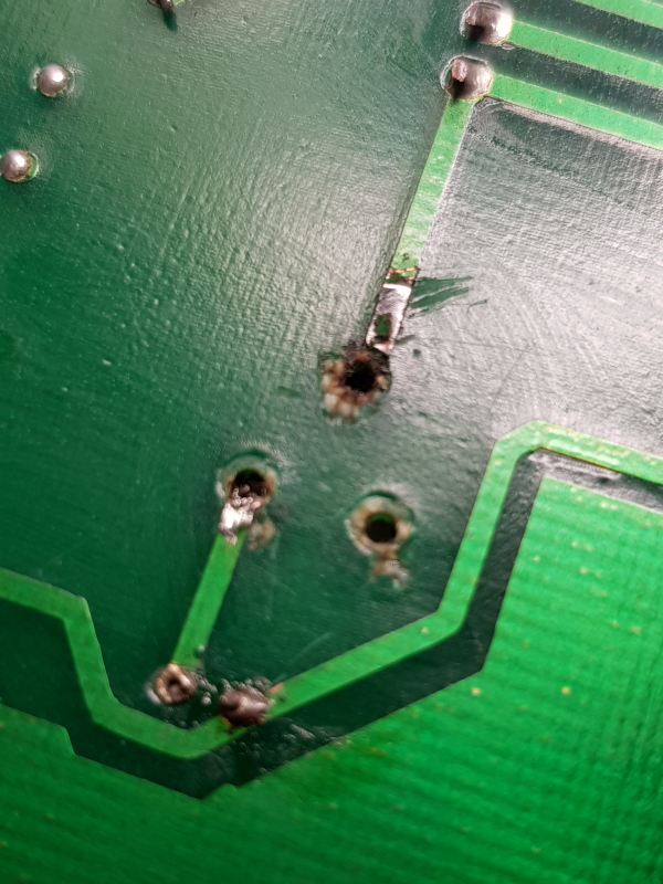
I removed it and found some bad track damage underneath and on top
I fitted a new pot and patched all this up nicely but I still had no sound.
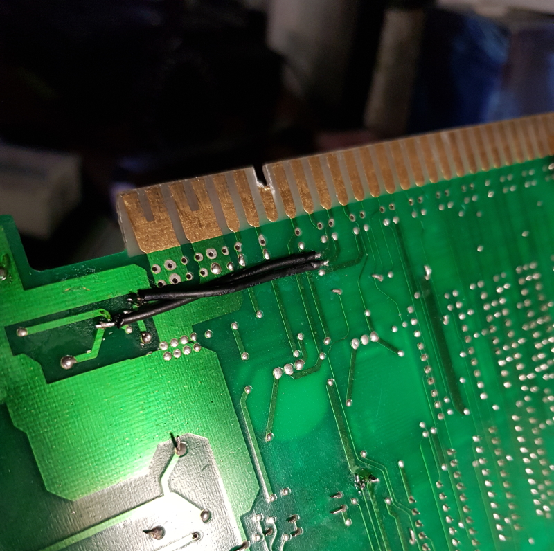
Tracing it out revealed that the bootleggers mixed up the two SPEAKER connections so SPEAKER+ was connected to SPEAKER- on the JAMMA edge and vice versa.
I spoke to Muddymusic to see what he wanted me to do. The option were hack the board to swap them or make an adapter. The prior option was chosen and I cut the two traces and ended up with this solution.