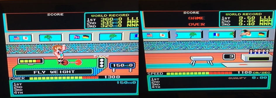
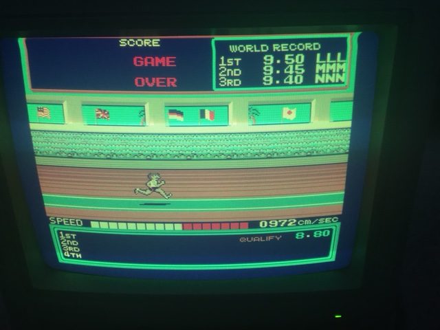
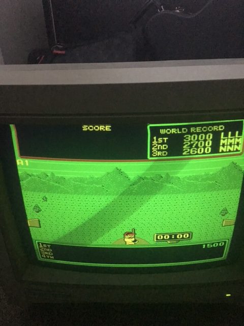
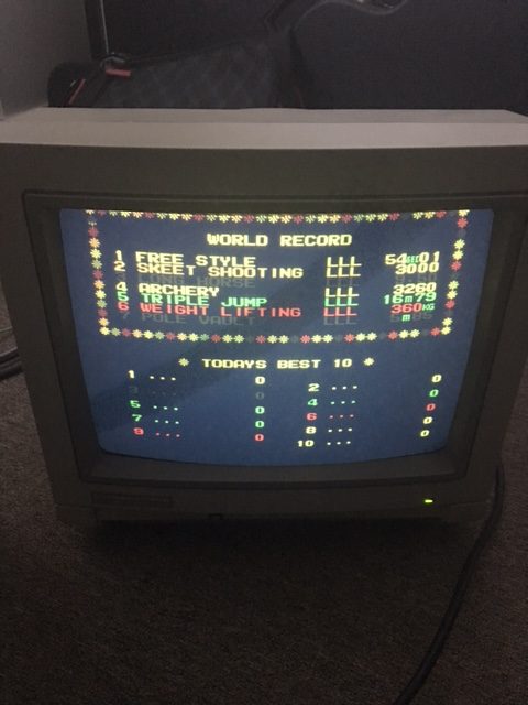
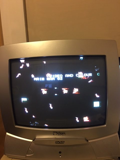
In this log I fix the sprite’s incorrect colors as discovered in part 1. To review the problem see the image below. Note that the colors for the weightlifter are incorrect, the runner also has red shadow instead of black and the colors for the area in between the flags on the right are also incorrect.
Initially, I thought the area between the flags were actually made up of background tiles. These are actually sprite objects used as background graphics. I used my test rom to confirm this.
The bipolar proms I ordered finally came but were all faulty! So that was a complete waste of time and money. The good news is after checking the palette prom [ several times over ] it appears to be good and I must have been reading it incorrectly with my TopMax in part 1 of the repair log.
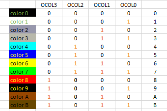
I thought about this for awhile and had an idea that would help me troubleshoot. Firstly, I looked at the color palette for Hypersports in MAME and took down some notes.
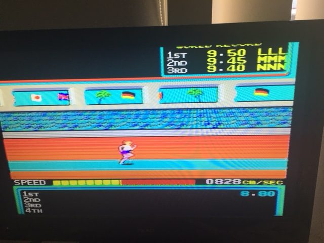
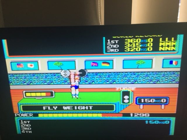
After comparing the colors of the sprites from images online [ google images was a good starting point ] with colors from the table above, my suspicions were that there was a stuck bit somewhere. Black [ color 0 ] is being displayed instead white [ color 1 ].
For black [ color 0 ] to be displayed instead of white, bit 0 would have to be stuck low. Color 2 is also being shown instead of color 3 and the only way this could happen is if bit 0 was stuck low. The athlete’s shadow is also being shown as red instead of black for the same reason which results in color 8 being shown instead of color 9.
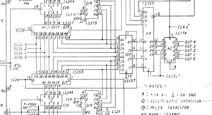
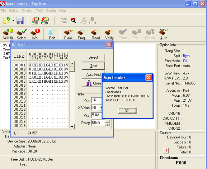
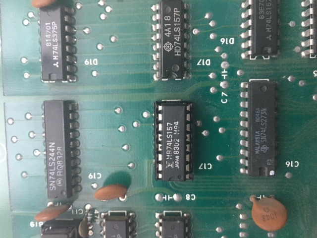
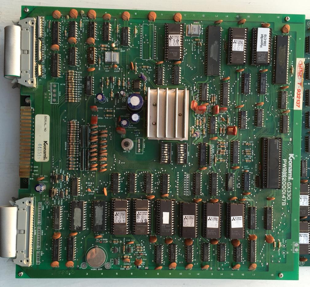
The backgrounds and sprite data appear to be combined at the LS157 at A4 which then form the signals OUT0-OUT4 at the LS174 A2. These 5 signals represent the color of a single pixel on the screen [ 32 possible colours ]. But I’m more interested in the signals OCOL0-OCOL3 [ object/sprite colors ] so I begin poking around at the inputs and outputs of the LS157 at C17 first. I generally choose the multiplexers to troubleshoot first whenever it’s relevant because these seem to get worked fairly hard [ especially in the video circuit ] and exhibit higher failure rates in these areas.
Pin 4 [ 1Y ] output of C17 appears to be stuck low, exactly what I was looking for. This was later confirmed after testing the chip out of circuit.
The Fujitsu in C17 is a temporary measure, I promise. It’s a working pull from my Gyruss and I didn’t have any other spares on hand.
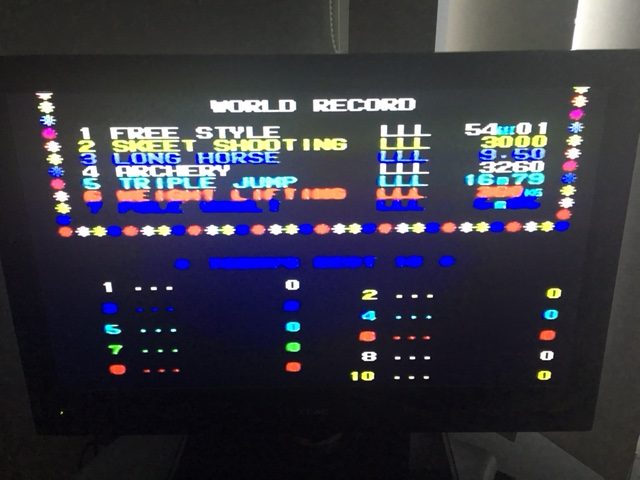
The colors seem right although I seem to be missing overall color from the CRT.
Changing it over to my LCD just to confirm that my 1084 probably needs an adjustment of some sort.
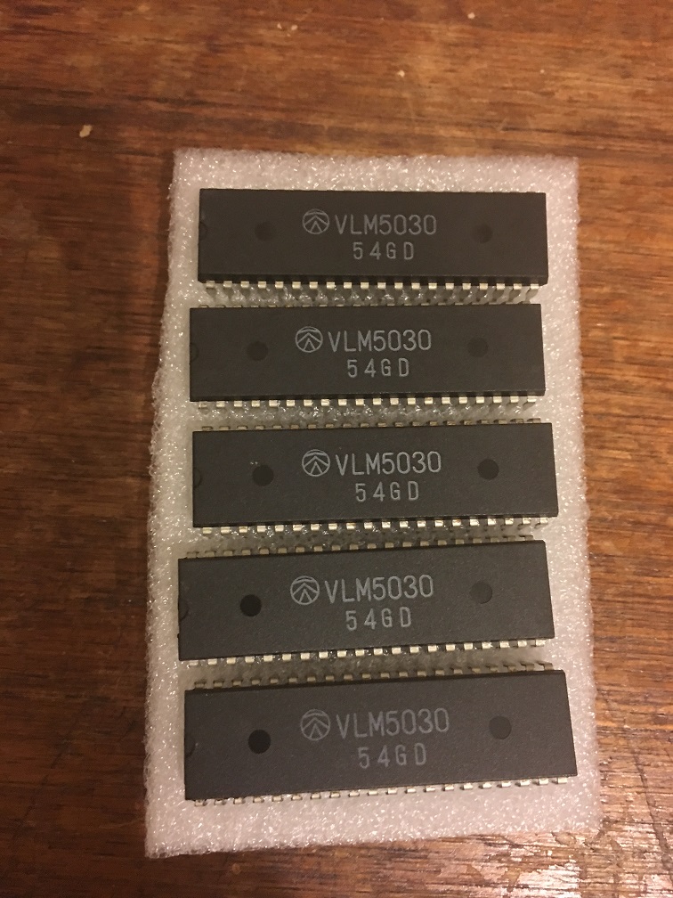
This is a very short update which covers the replacement of the VLM5030 Speech Synthesizer chip which Konami used in various games.
https://www.system16.com/hardware.php?id=556
Today my eBay order of 5 x VLM5030 Speech Synthesizer chips arrived in the mail. I only needed one but who knows when the other 4 will come in handy for future repairs.
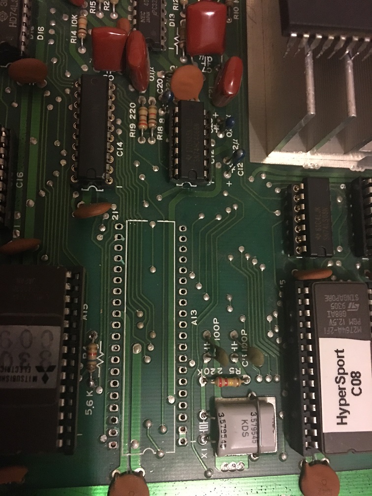
Removed the old IC. It’s probably not clear from the picture but this IC got very hot at some point. The marks left aren’t as obvious as what I discovered under the 2149s at A19 and B19, I might need to look at those later.
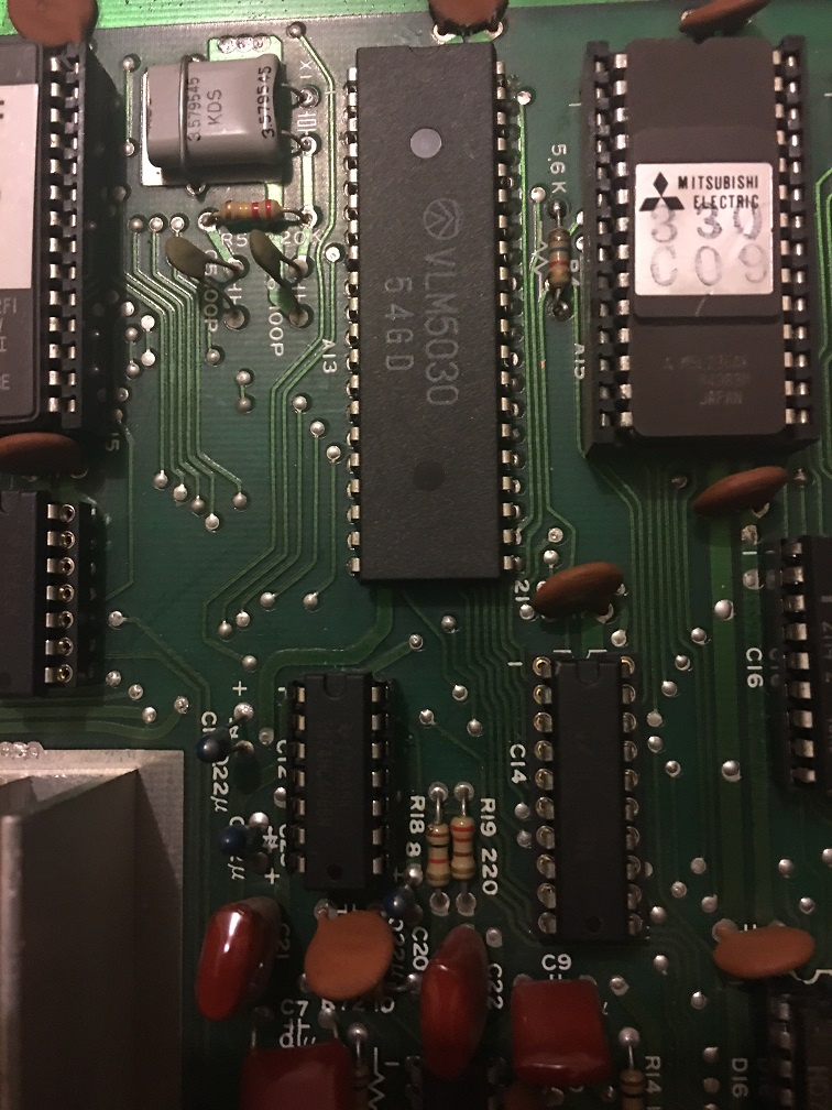
I didn’t have any 40 pin sockets available but I was really itching to try this out so I soldered the chip in anyway.
Cycling through the sounds and playing them in diagnostic mode verified the fix for this. I also ran the game to verify this as well.
This version has been tested on real hardware. Thanks to a KLOV member [ thanks PinballPatTN ] for loaning me his faulty board and allowing me to finally get the code fixed.
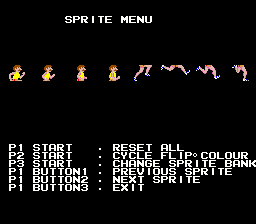
Sprite rams are banked at 0x1000-0x13ff and are enabled/disabled via IRQ.
Changes and improvements
Improved runner animation frames which were incorrect previously.
H8,H9 and J8,J9 object rams are now cleared and tested properly.
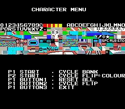
Enabling DIP 5 puts the game in diagnostic mode on power up.
Various fixes and improvements.
TODO:
Determine if the actual hardware supports flipy for the character display. Currently, flipping the character set in this direction results in a blue display [ blank set of tiles ]. This seems to work in MAME but not on real hardware.
23/08/2015
This is an initial test release. A BETA version will replace it and this post will be updated pending sufficient feedback.
This EPROM installs on the CPU board @ G15. This does not replace the original software in G15 but is only used as a means of testing the main-board, sound and video.
Diagnostic mode is accessible by holding down player 2 start whilst powering the game on.
In the normal mode ( power up tests ), nvram tests may be skipped to preserve high score data if so desired. This is done via DIP 3 of SW2. A ~10 second countdown is also included even if you desire to test your nvram, in this mode nvram tests may also be skipped by pressing the “player 1 button 1”.
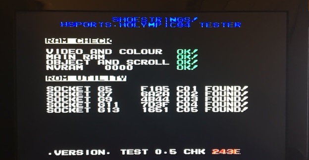
Power up tests also include a rom utility. This currently identifies Hypersports/Hyper Olympic84 software in any of the 5 available sockets ( G5 to G13 ). For example, a C06 ROM installed in any of the above available sockets will still be identified for its designated G15 socket.
I’ve decided to do this in two parts, the reason for this is that the faults to this board are so extensive. I am convinced that this board was hit by a bolt of lightning.
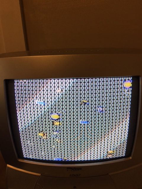
Symptoms – game booting to a screen full of zeros and watchdog barking. Z80s reset pin was also asserting but the sequence was incorrect ( just a hi flashing signal on the logic probe with no low ). There was also a perpetual low frequency sound with a higher pitched sound superimposed on top of that.
Did the usual troubleshooting. +5.15v voltage at the edge and 4.5v at the chips. Thought this was a little low. Something is dragging it down, I decide not to panic too much.
A previous repair was attempted so I decided to check all the socketed chips out of circuit first before proceeding with my own troubleshooting. Brand new components H16,E12,G17,G18 and the 74LS245 at H17 tested good. All EPROMs on the top board checked out fine with romident.
The owner of the board mentioned that the board was activating the coin meter on its own, then that eventually stopped. I take a stab at the 74LS08 at A2 which seems to drive COIN 2. My logic probe registers dead outputs on the chip and it tests bad out of circuit too. Of course changing it made no difference to how the game runs. I would soon discover that the 74ls08 seems to be a high failure Fujitsu component in this board.
Troubleshooting the z80 reset
I wanted to check out what was going on with the strange reset behavior of the Z80 reset line first.I remove D18 and test it out of circuit, sure enough it tests bad so I replace it. This fixes the reset signal and it’s now going from low to high as expected. Half the pins on the z80 are floating and the data lines aren’t toggling so I remove it and install a replacement from a parts board. The new z80 is alive although not for long before the CPU crashes and the data lines get stuck again.
At some point in the repair the Z80’s data lines stopped toggling again from an initial reset. I traced this to stuck enables on the LS138 at C18 which tested fine out of circuit but the 74LS08 at C9 feeding /G2A on C18 actually failed. Replacing C9 fixed it again. I still had stuck /OEs on both sound EPROMs but I would look at this issue later.
For some reason A16 on the bottom board caught my attention, of course this was a Fujitsu branded 74LS08 as well. I had a brand new one in my hand so I thought “what the hell” and piggy backed the new one on top of it. This seems to have cleared the screen with the initial junk. I also found another bad 74LS08 at H2 which changed nothing after replacing it.
I also found 4 additional bad chips @ F13, E15,C12 & C14 and replaced those with no obvious change.
Troubleshooting the Konami1 – watchdog / reset issue
With pin 19 barking furiously I decided to trace it’s origin thinking that perhaps there was a problem with the watchdog. Both /E and /Q clock frequencies were correct on the CPU ( 1.53Mhz ) .
I found a bad resistor at r43 ( measured 2kohms instead of 1kohm ) so I replaced it, no change.The reset signal actually originates from the bottom board .I traced and tested every chip in it’s path starting from the Konami1. ( top board [D18, B2 then the CR13 connector], bottom board [A1,G2,C4, 504 ]. G2 ( Another Fujitsu 74LS08 ) tested bad, replacing it didn’t change anything after testing. I was starting to lose confidence at this point.
I started to probe the /OE enables to the game EPROMs and saw that every single output was stuck high right from reset. Pins 4 and 5 ( /G2A and /G2B ) of the LS138 @ H16 were floating. For y0-y7 output to go active low, the two above mentioned inputs must be low. Since pins 4 & 5 are tied together I traced this back to pin 28 output of the Konami1. I replaced the CPU temporarily with mine from my Gyruss PCB and now I was getting a screen full of Hs, This meant that the CPU was actually executing code from ROM.
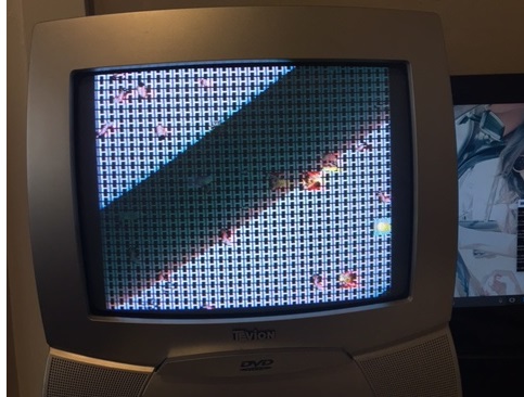
I installed the original CPU back into the PCB and measured around 1v on the inputs of pins 4 & 5 of the LS138. I would soon discover that the CPU was faulty on this line only. This CPU actually works fine in my Gyruss board [ Gyruss does not use the output of pin 28 of the Konami1 ]. So I added a 1kohm pull down resistor between pins 4,5 and ground on the LS138. This pulled the 1v down to more acceptable TTL levels and I finally got this CPU to boot to the screen full of Hs just as you see above with the good CPU. The sprite colours now seem to be showing incorrectly with red streaks compared with the last screenshot.
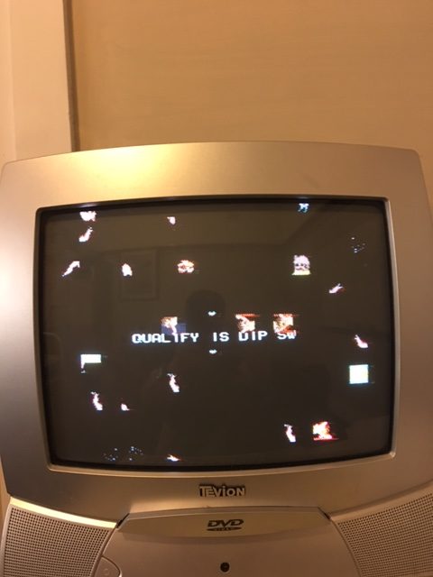
I installed my testrom into G15 which showed that the main RAM at G2 was bad.
I removed the RAM, socketed the board but the RAM tested good in my TopMax. I probed the RAM with my logic probe and saw no write enable active at all. That would do it! It seems there was a broken trace right near pin 8 of H11 when removing the chip, this was the write enable output to the main RAM. Reconnecting this line fixed the RAM error. The game was finally able to boot with the typical HS issues.
Revisiting the stuck /OE on the sound EPROMs
This ended up being bad 2114s on the top board ( C16 & C17 ). After replacing these I now had sound but unfortunately speech isn’t working. The data lines on the chip are all floating and there seems to be no clock at all. At this point it looks like a bad VLM5030 chip which I’ll have to look at later when I can get a spare.
Video issues
Replacing all four 2114s on the bottom board fixed the flickering but the colour issue still remained. I removed all bipolar PROMs and they all had the wrong checksums. So I’m going to order some and hope to fix the that also.
I’ve also decided to start using my LCD instead of the CRT which seems to have some issues displaying colours at the correct position near the edges of the screen.
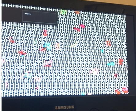
After replacing the 2114 rams the Hs look a little wonky and there are some still random sprites. I’m hoping this is normal though. I’m guessing it is since the game code hasn’t had the chance to clear the object and scroll ram so it probably takes on some random values causing the wonkyness and random sprites before proper initialization takes place.
Re-working the Hypersports testrom.
My Hypersports testrom has not been that useful at this point with the text wrapping around the screen and I should have never released it in the first place without testing it myself on real hardware. The 2114 rams on the bottom board are actually banked and occupy the same address by enabling and disabling hardware interrupts ( IRQ ). I had some trouble clearing the scroll and object RAM and it turns out I was only clearing H8 & H9. By enabling interrupts and modifying my code I was able to clear J8 & J9. I confirmed this after looking at the schematics [ the IRQ input to H2 and one of its outputs /OBJSEL ]
I wrote some code to test this and I was able to clear the screen correctly after setting up and enabling the IRQ, then writing 0s from 0x1000 – 0x13ff within the interrupt routine. The results are more than I could have hoped for.
Now all I have to do is implement the checks on J8 & J9 within my IRQ routine. Once that’s done and the necessary changes added then our runner should appear across the screen just like in T&F 🙂
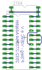
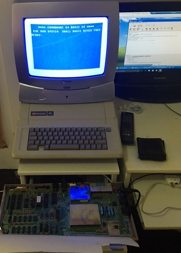
This is part two of my C64 repair which documents the replacement of the bad character generator rom using a standard 27c64 EPROM. My local electronics hobby store did not have anything else on hand; I was hoping for a 27c32 because that’s what most folks on the internet seem to be using to get this repair done. I didn’t want to wait, so I settled on the 27c64.
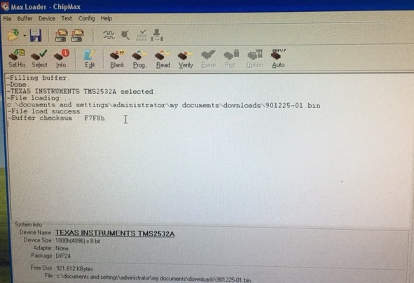
The first step was downloading a c64 character rom ( 901225-01 ) with a checksum of $F7F8 from the internet. There are plenty of sources for these.
After downloading the 4kb binary I ran the following command under Windows to fill up the entire 8kb of address space of the 27c64 ( upper and lower 4kb have the same data ). I couldn’t quite remember which half I needed to burn the contents to so this was a quick and fail safe solution.
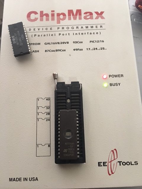
Once I finished wiring it was time to double check my work. I then select a 2532 device on Max Loader, load the original downloaded character generator rom into the buffer; this has a checksum of F7F8 which will be used for verification purposes.
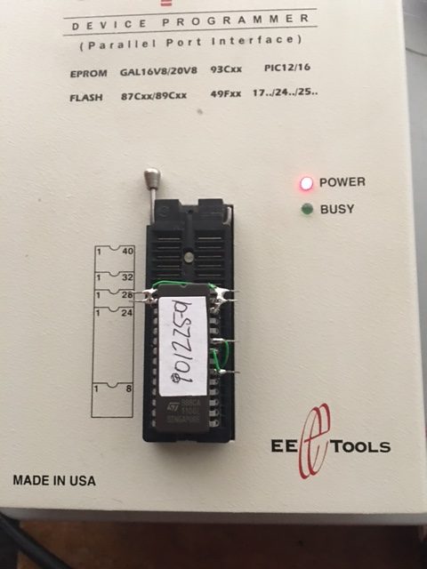
With the wiring complete I’m now ready to verify it’s contents. I will read the device as a 2532 EPROM and if all goes well it should report a checksum of F7F8
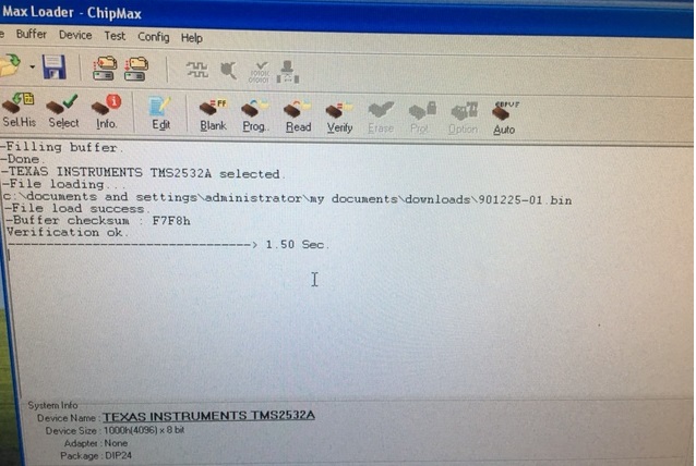
With the re-worked EPROM inserted into the ChipMax I hit verify. F7F8 was what I was after.
With that result I was so confident it was going to work that I trimmed the protruding pins and inserted the device into the C64 to produce the results I expected.