Yves M

Quartet repair log

 PCB Repair Logs, Repair Logs  Comments Off on Quartet repair log
Mar 042016
 

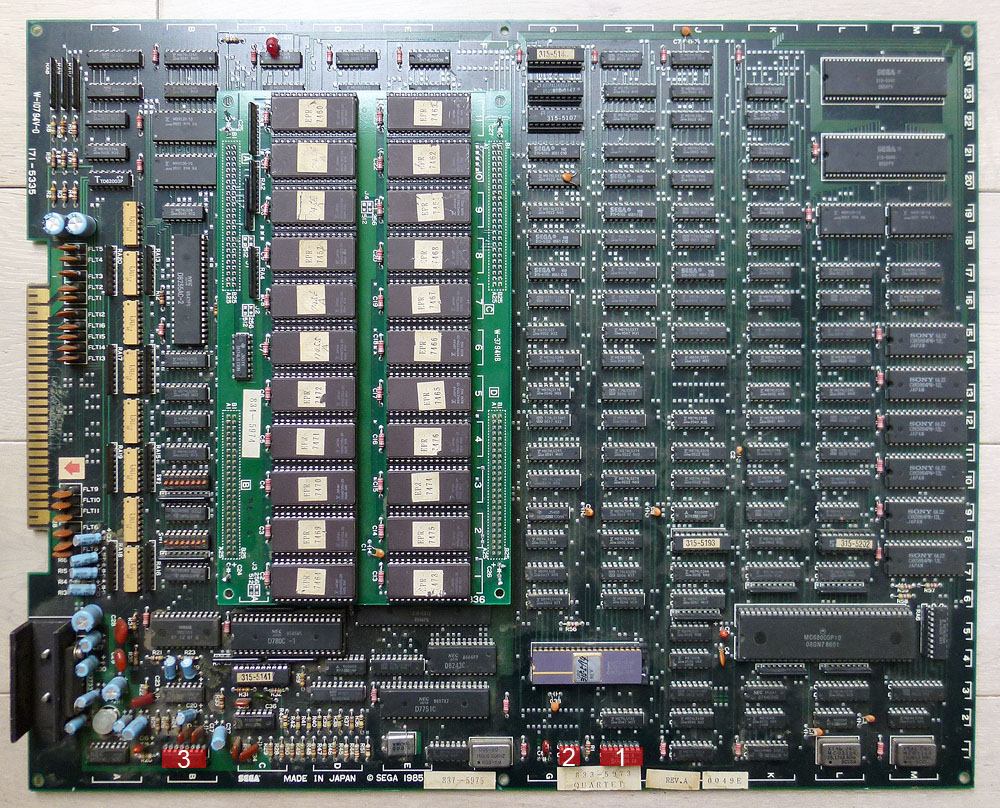
Here is a recently repaired Quartet running on Sega pre-system 16 hardware.

quartet1

The 3 replaced chips are highlighted in red. I will explain every step of the repair process below.

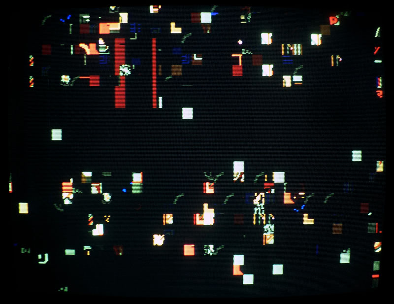
1) The game was booting to a garbled screen:

quartet2

The 74LS04 located at 1H (an inverter, manufactured by Fujitsu) had good clock signals on entry pins 11 and 13 but had floating signals on outputs pins 10 and 12. Replacing the chip changed the result on boot…

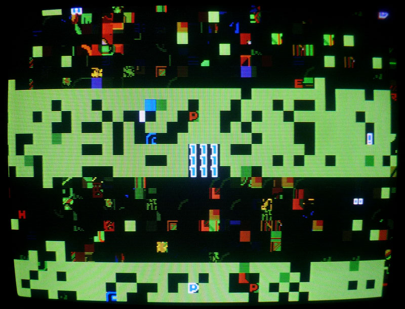
2) I then got a screen with garbled graphics but with a countdown appearing at the center.

quartet3

This is normal on pre-system 16 games. Normally, after reaching 0, the game is booting. Here, I got a black screen after the countdown.

I noticed that the reset pin on the 68000 had a square looking wave signal, which was pretty weird (it should be a linear signal at +5V). The chip that generates the reset signal is a MB3771 located at 1G (again, manufactured by Fujitsu). Probing its pins made the game sometimes booting. I replaced it by a new 3771 chip and the game was now starting normally.

quartet4

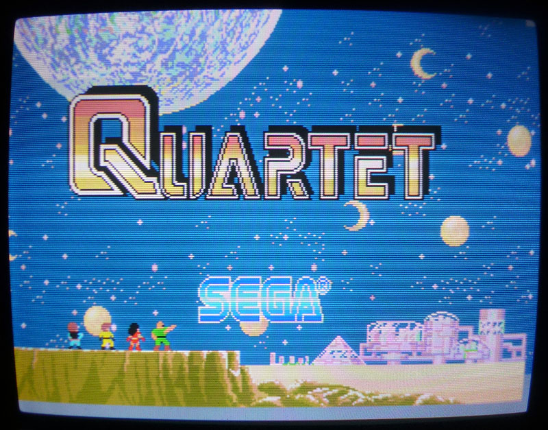
3) The game was working and playing fine except for the FM sound that was inoperative (only the voices could be hear). It was due to the YM3012 located at 1B (a DAC). It had good looking signals on its inputs but nothing seemed to get out of its outputs. After replacing it I got the FM sound back.

Now the game is fully working.

Feb 122016
 

Here is a picture showing a recently repaired Rastan PCB with the replaced chips highlighted in red.
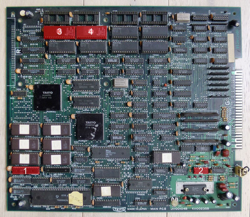
rastan2-5

I will explain every step of the repair process here:

1) When powered up, the game was starting but was constantly rebooting after about 5 seconds. I checked the reset pin on the CPU but it was constantly high so that seemed not related to that. I checked the signals on the 2 CPU RAMs @ IC10 and IC22 (2x TMM2063 – 64kb) but nothing seemed suspicious. Anyway, piggybacking the one @ IC10 made the game not rebooting after 5 seconds but after a longer time. That was sufficient to let me think it may be faulty so I desoldered the RAM and it was tested bad on my programmer. Replacing it by a new one made the game working and not rebooting again and again. Good.

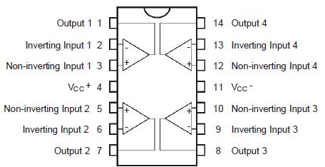
2) Well, the game was now playable but there was no FM sound (so no music at all), only voices were audible. Schematics are available online so I could see that the FM sound is generated by the YM2151 @ IC63 then it goes to an YM3012 DAC @ IC78 then it goes to a TL074 op amp @ IC100 to finally going to the MB3731 amplifier @ IC101. Outputs signals looked healthy at the outputs of the YM2151 and I had correct sound for the voices so the issue should be located before the mix between FM and voices signals, so before the amplifier: more probably within the DAC or the op amp. The TL074 is composed of 4 operational amplifiers:
rastan2-6

I noticed that every of the 4 output signals on the TL074 @ IC100 were looking weird with a negative voltage (between -1 and -2 V). There is another TL074 chip on the board that is related to the voices and every outputs showed a positive signal of approximately 2.5 V. That was suspicious so I desoldered the TL074 @ IC100 and replaced it by a new one and the FM sound was back ! (the signals on every 4 outputs were now showing a positive analogic signal of approximately 2.5 V).

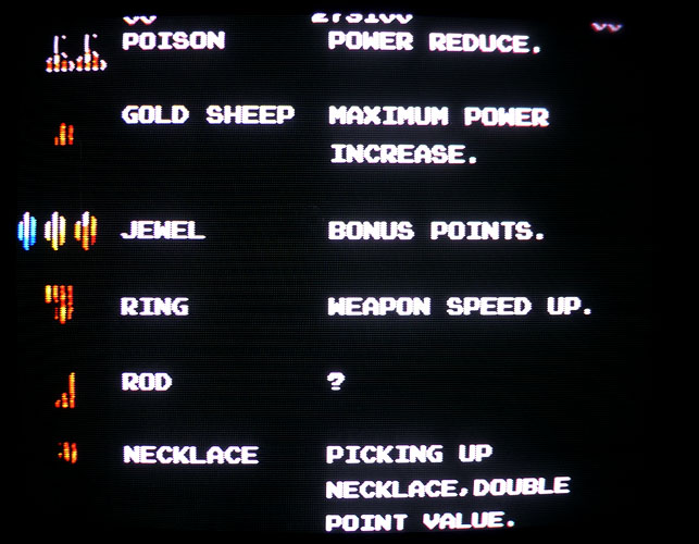
3) and 4) Ok, so then the game was fully playable with perfect sound but there was some graphical glitches on a few items, as seen here in the attract mode:
rastan2-3

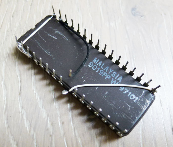
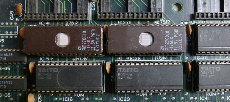
I have a previously repaired Rastan PCB that had one of its gfx mask roms replaced by an hacked 27C010 EPROM so, due to the nature of the problem here (glitches on only a few particular items), I suspected one or multiple MASK ROMs to be faulty. I started replacing these ROMs with the ones from my working Rastan PCB and got the gfx working perfectly after replacing B04-07 @ IC14 and B07-08 @ IC27. As noticed in my previous Rastan repair log, the gfx ROMs on this board are 128kb fitted into 28 pins chips. Finding blank chips with these exact specs is hard nowadays so I used 128kb 32 pins 27C010/27C1001 EPROMs as replacement (I could use a 27C1000/27C301 EPROM to make the modification even easier but I didn’t have one remaining then). To fit them on the 28 pins sockets present on the Rastan board, you have to make the following modifications on every EPROM:

If you use a 27C301 or 27C1000 non-JEDEC EPROM (simplest way):

  • Connect pins #30, 31, 32 together and connect them to pin #1 with a small wire.
  • Connect pin #2 to pin #16 with a small wire.

If you use a 27C010 or 27C1001 JEDEC EPROM:

  • Connect pins #30, 31, 32 together and connect them to pin #1 with a small wire.
  • Gently bend pin #24 so it won’t plug into the socket and connect it to pin #16 with a small wire.
  • Solder a small wire on pin #2 that you will plug into pin #22 of the socket.

I did these connections on the underside of the chip. Here is how it looks on my 27C010:
rastan2-2

And this is how it looks after the 2 chips plugged in:
rastan2-1

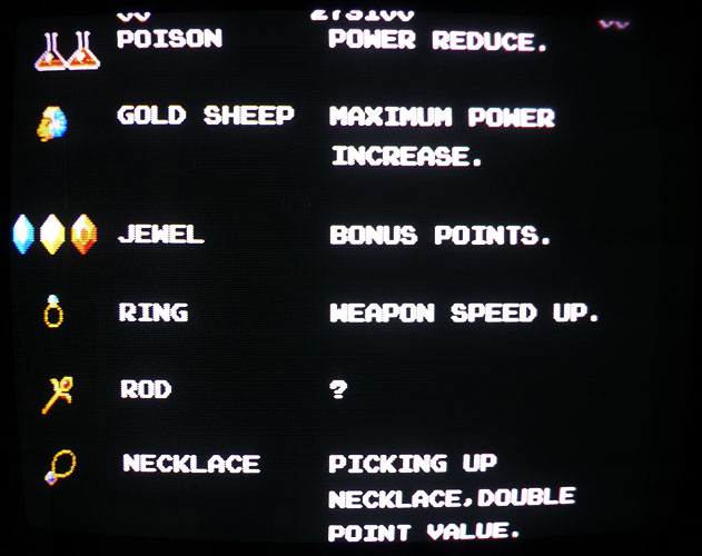
Now the gfx are fully restored, as well as the rest:
rastan2-4

Gryzor repair log #2

 PCB Repair Logs, Repair Logs  Comments Off on Gryzor repair log #2
Jan 232016
 

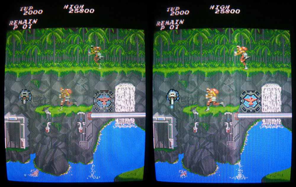
A friend got a Gryzor PCB working but with problems on some of the sprites (mostly enemies and items with half of the horizontal lines missing).

The 4 GFX MASK ROMs were tested ok on another Gryzor PCB. Looking with the scope on the RAMs revealed nothing really suspicious.

I then piggybacked the RAMs around the GFX part and quickly found the faulty one.
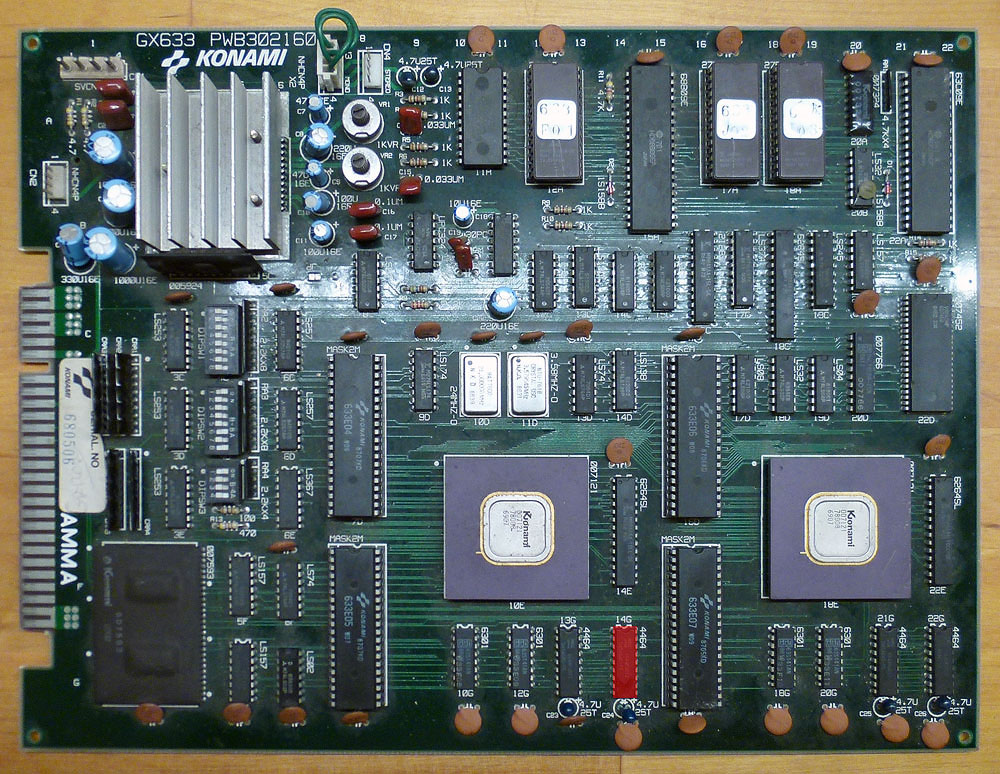
It was the NEC 8644FU12 at location 14G. This RAM is a 4464 (64k-word x 4-bit, same type than the ones I replaced on my recently repaired Final Star Force).
Here is a picture of the PCB with the faulty chip highlighted in red:

gryzor2-1

Piggybacking it with a compatible TMS 4464-12 restored all the sprites.
In fact, the problem was so small that it was impossible to see any suspicious signal on any of the pins of that RAM with the scope (every signal looked healthy). I replaced the chip and obviously got the PCB running perfectly.

Here is a before and after picture:

gryzor2-2

Jan 062016
 

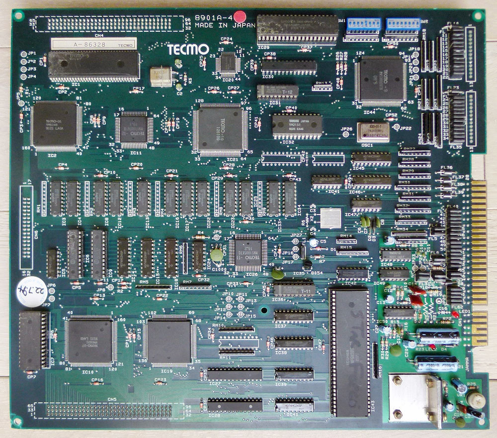
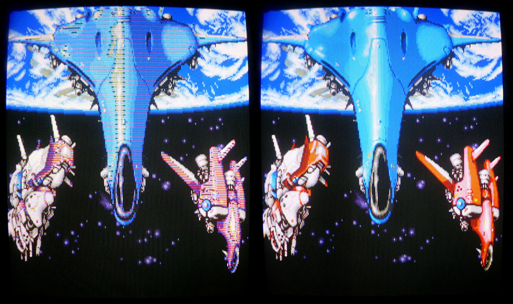
Recently got this Final Star Force PCB with graphical glitches on the sprites.

fstarforce1

This game uses a motherboard (pictured above) and has a romboard on the other side fitted with no other chips than the game’s ROMs.

All the ROMs were tested ok on my programmer and cleaning the connectors and looking at the signals, everything seemed fine with that romboard.
The motherboard has a rather simple layout with a lot of RAMs, some ASICs and a few TTLs. After a few hours looking for suspicious signals, I finally found the faulty ones.

There is a row of 12 Sanyo LM33464G RAMs (64k-word x 4-bit). Two of them were bad (the ones at IC22 and IC33). Piggybacking them with new ones partially brought back clean sprites, even if there were a few glitches remaining. These glitches totally disappeared after replacing the RAMs.
As these models of RAMs are a bit uncommon, I took compatible TMS4464 as replacement (highlighted in red):

fstarforce2

Here are before and after pictures:

fstarforce3 fstarforce4

Jan 032016
 

Contra / Gryzor shares almost the same hardware specs with Combat School / Boot Camp, Fast Lane, Flak Attack / MX5000, Haunted Castle / Akumajô Dracula and Trick Trap / Labyrinth Runner.

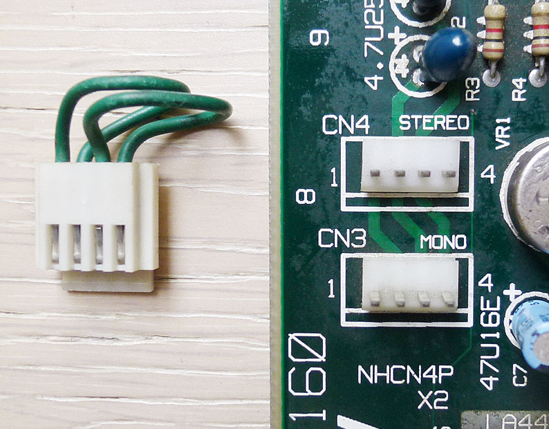
But among these titles, it is the only game that offers a stereo output thru a 4-pin connector on the board (labeled CN2).

First, you have to select stereo by plugging a connector on CN4 (and put switch 4 of DIPSW3 to off).

contra-sound

The thing is that all the boards I’ve seen still delivers mono sound when you plug this connector (originally brought by Konami and present on the board) on the stereo plug. Why ? Because it doesn’t have the good wiring…

As shown on the picture above, this connector originally comes with pin #1 wired to #2 and pin #3 wired to #4. In that way and plugged on the stereo connector (CN4), it mixes channel 1 and channel 2 from the YM3012 DAC to the LA4445 amp which results a mono output.

To separate the channels, you have to simply modify the connector by wiring pin #1 to #3 and pin #2 to #4.
Now plug it on CN4 and enjoy stereo sound out of CN2. 🙂

There are other Konami games that use the same connector to choose mono or stereo. I’m not sure about the wiring for every game. To my knowledge they are:

Salamander
– Jackal / Top Gunner
Devil World / Dark Adventure
– Gradius II / Vulcan Venture

– Ajax

Lightning Fighters / Trigon (stereo works without modification of the connector)
– Parodius
(stereo works without modification of the connector)
Surprise Attack (that game seems to have a mono sound design, despite the stereo connector present on the board)

ps. If anybody knows if the original wiring on these boards allows to deliver stereo sound or any other board that is using this connector, I would be glad to know and add it here.