Yves M

Gryzor repair log #1

 PCB Repair Logs, Repair Logs  Comments Off on Gryzor repair log #1
Dec 142015
 

First I would like to thank hezkezl and channelmanic on the KLOV forum for their help when I started diagnosing this Gryzor PCB last Year.

I finally got it repaired…

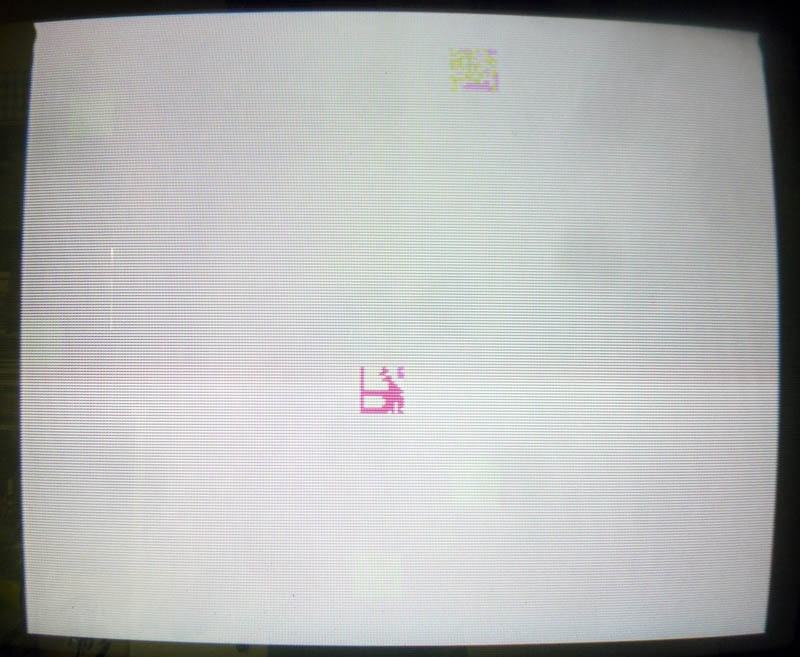
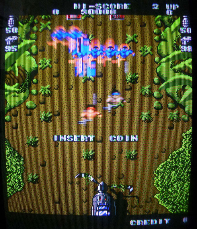
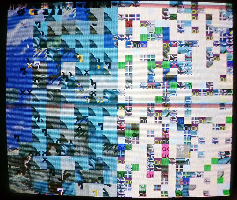
1) I got first stuck at this screen on boot:

gryzor0

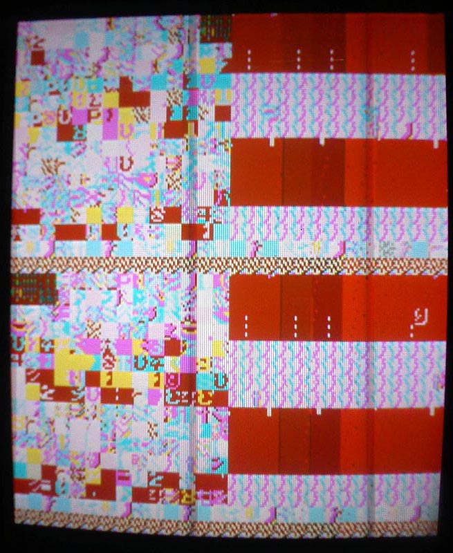
Dumping the program ROMs at 17A and 18A and comparing them with the ones from MAME revealed the checksum for the one labeled 633J2 at 17A was bad so I burned the rom from MAME on a 27C512 EPROM and put it in place but no changes.

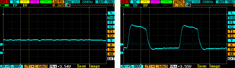
While checking the PCB with a scope, I traced a suspiciously weak signal from a couple of TTLs (which seemed ok) to a Fujitsu MB8464A RAM. Pins #7, 8 and 9 on this RAM were not pulsing (signal was stuck at 1,7 V).

These pins are address lines. They are connected to:
– Pins 7, 8, 9 on 18A and 17A (program ROMS)
– Pins 9, 10, 11 on 22A (63C09 CPU)
– Pins 114, 115, 57 on 10E (custom chip)
– Pins 114, 115, 57 on 18E (custom chip)
– Pins 1, 2, 3 on 14D (LS138 – Address decoder for I/O ports)

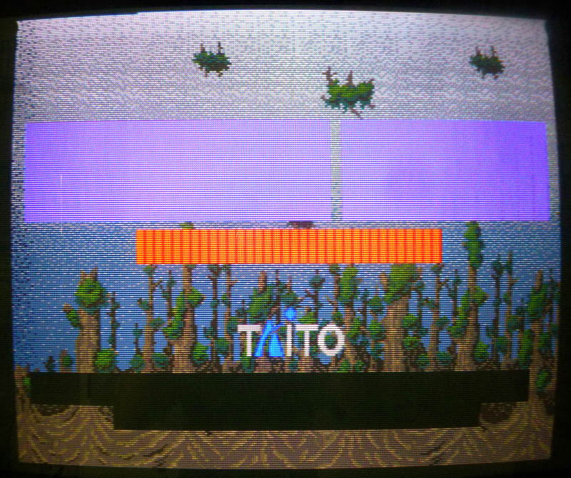
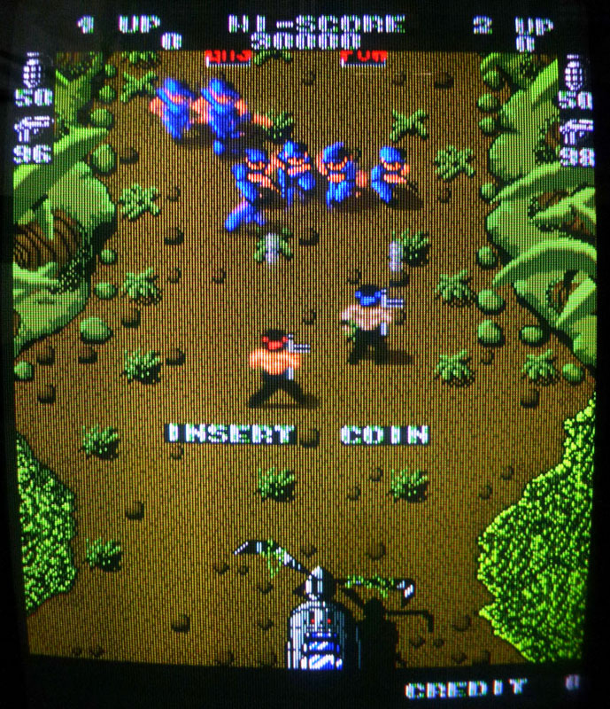
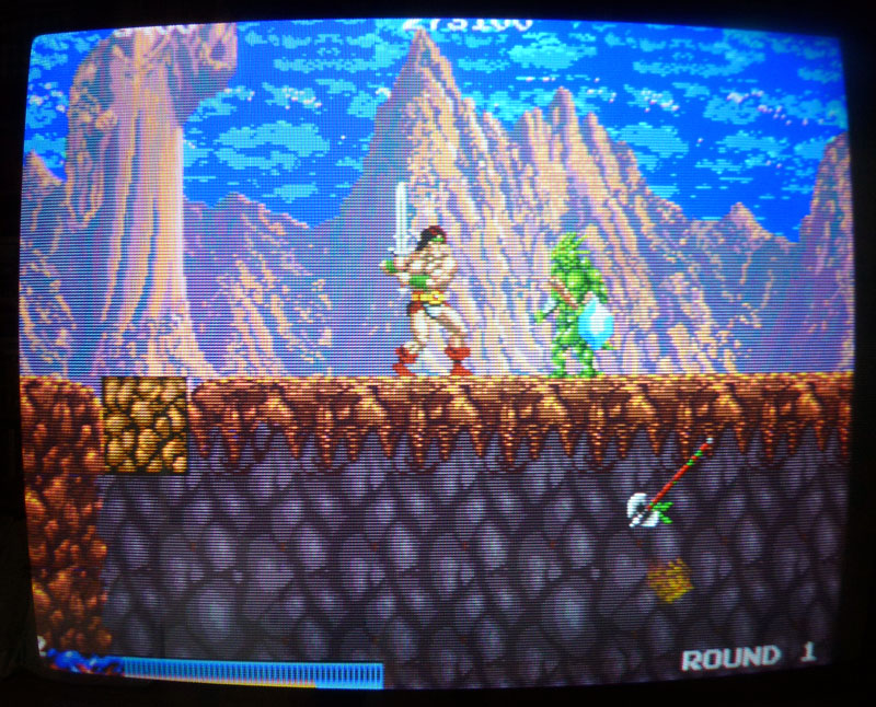
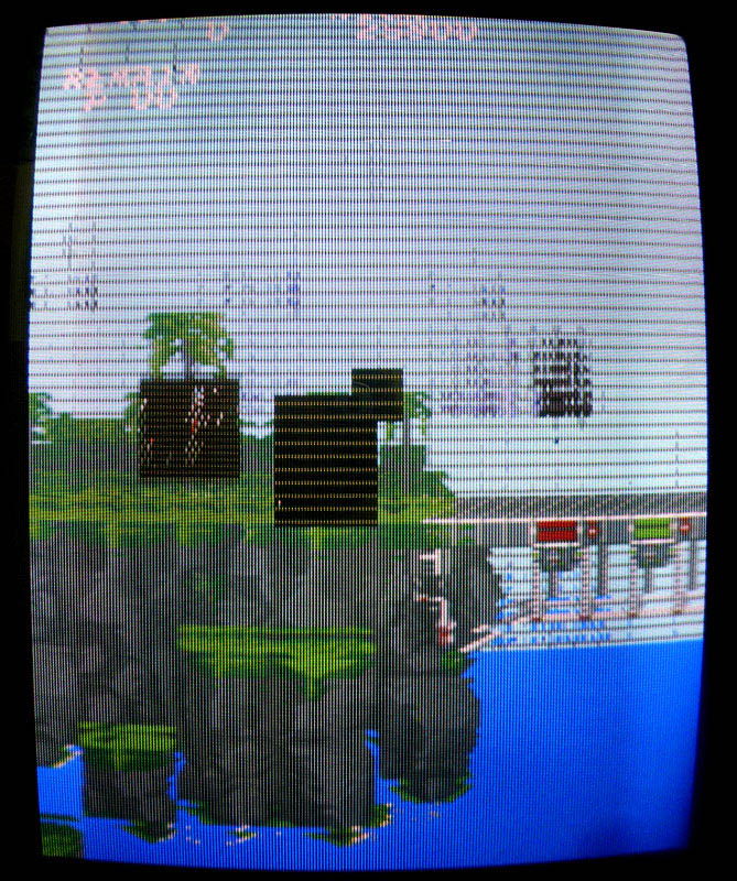
Replacing the LS138 at 14D didn’t change anything, not really surprising as it was related to I/O (but I didn’t really know that back in the time when I did it) so next I decided to replace the 63C09 CPU at 22A… And the game booted ! …with big graphical issues and no sound:

gryzor2

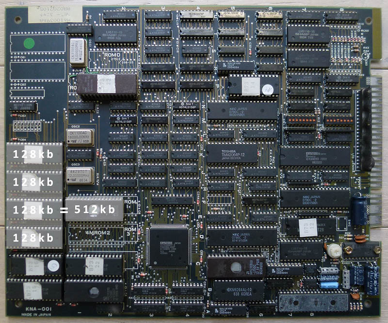
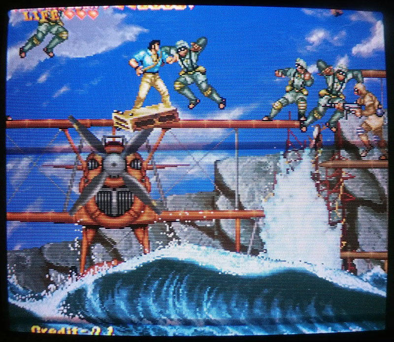
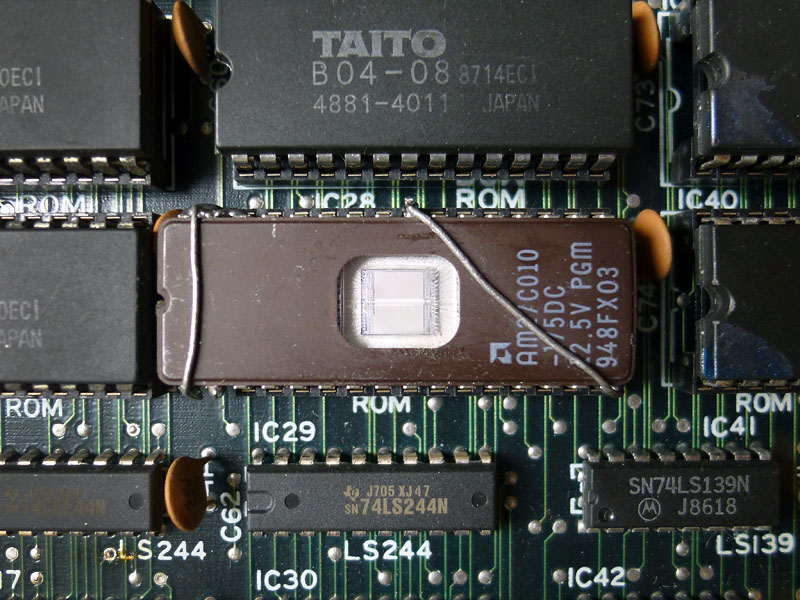
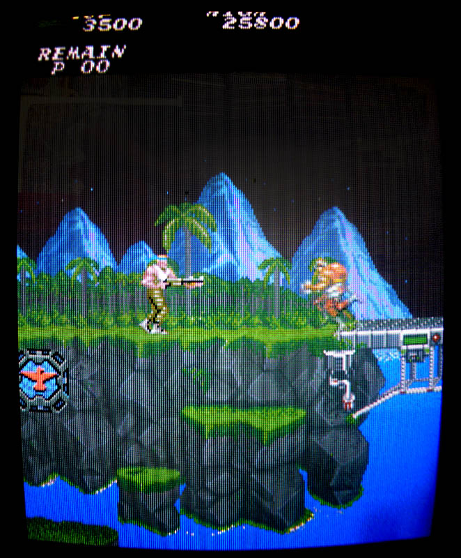
2) Graphics roms are the 4x 40 pins mask roms located at 7D, 7F, 16D and 16F. I’ve read online some people having problems with these chips and needed to replace them. The content of these roms is 256kb but I only had 512kb 27C400 EPROMs (equivalent pinout to mask roms) so I needed to double the size of each original 256kb roms to fit my 512kb EPROMs. A few tries revealed I had 3 bad roms (the ones at 7F, 16D and 16F) among the 4. All the graphics were now fine:

gryzor3

3) Good progress, but still no sound…

There are 2 chips in the sound part (located at 11A and 11B) that have their reference writings scrubbed, probably in factory to avoid bootleggers reproducing it. I’ve looked online to see if I could find pictures of other PCBs that could still have these labels visible, but all the ones I found had their writings scrubbed.

Anyway, it looked like these 2 chips were the sound generating chips. Looking in the MAME driver and on datasheets revealed it was a YM2151 coupled with a YM3012 D/A converter.

Looking at the pins of the YM2151 with a scope, I noticed there was no output signal on it (pin #21) while most of the other pins on the chip had pulsing signals. I desoldered it to put a new YM2151 in place and got a pulsing signal on the output pin… But still no sound.

I then started looking at the pins of the 63B09 sound CPU at 15A and found 2 dead signals at pins #16 and 18. These are address lines so I suspected the CPU and changed it. The sound was finally back. Everything is working fine now !

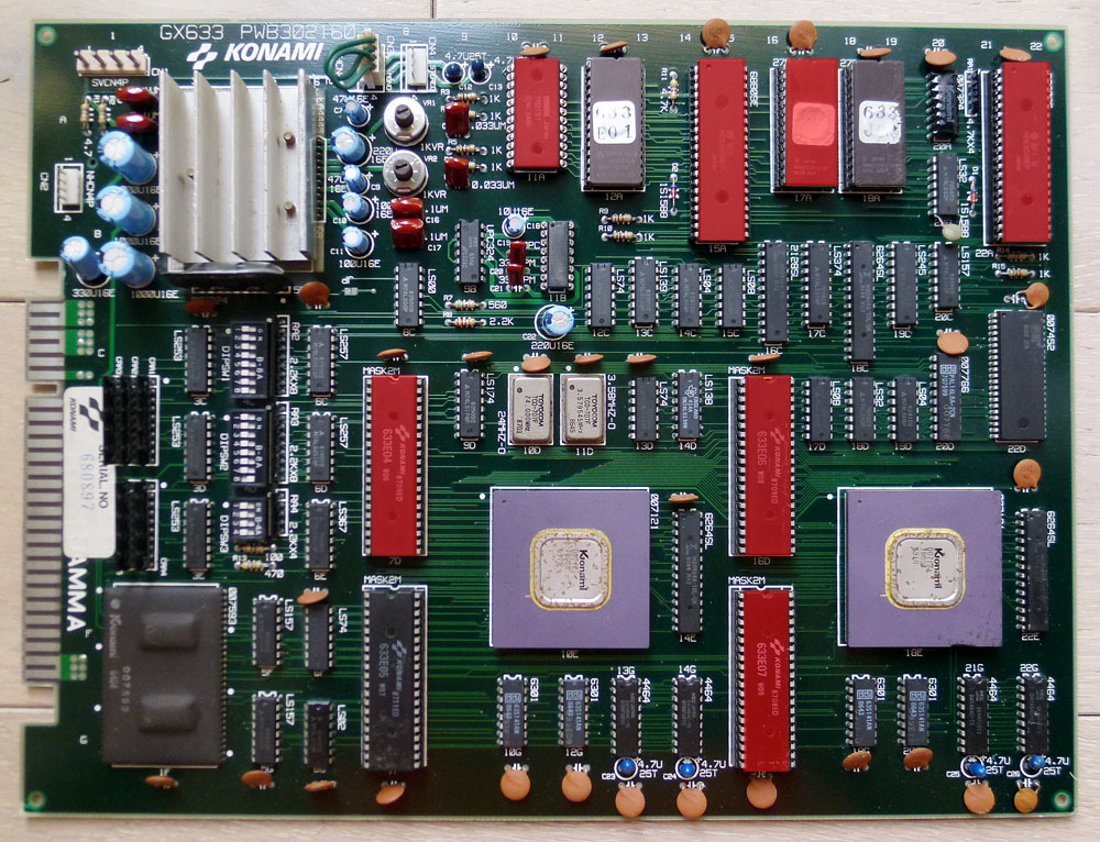
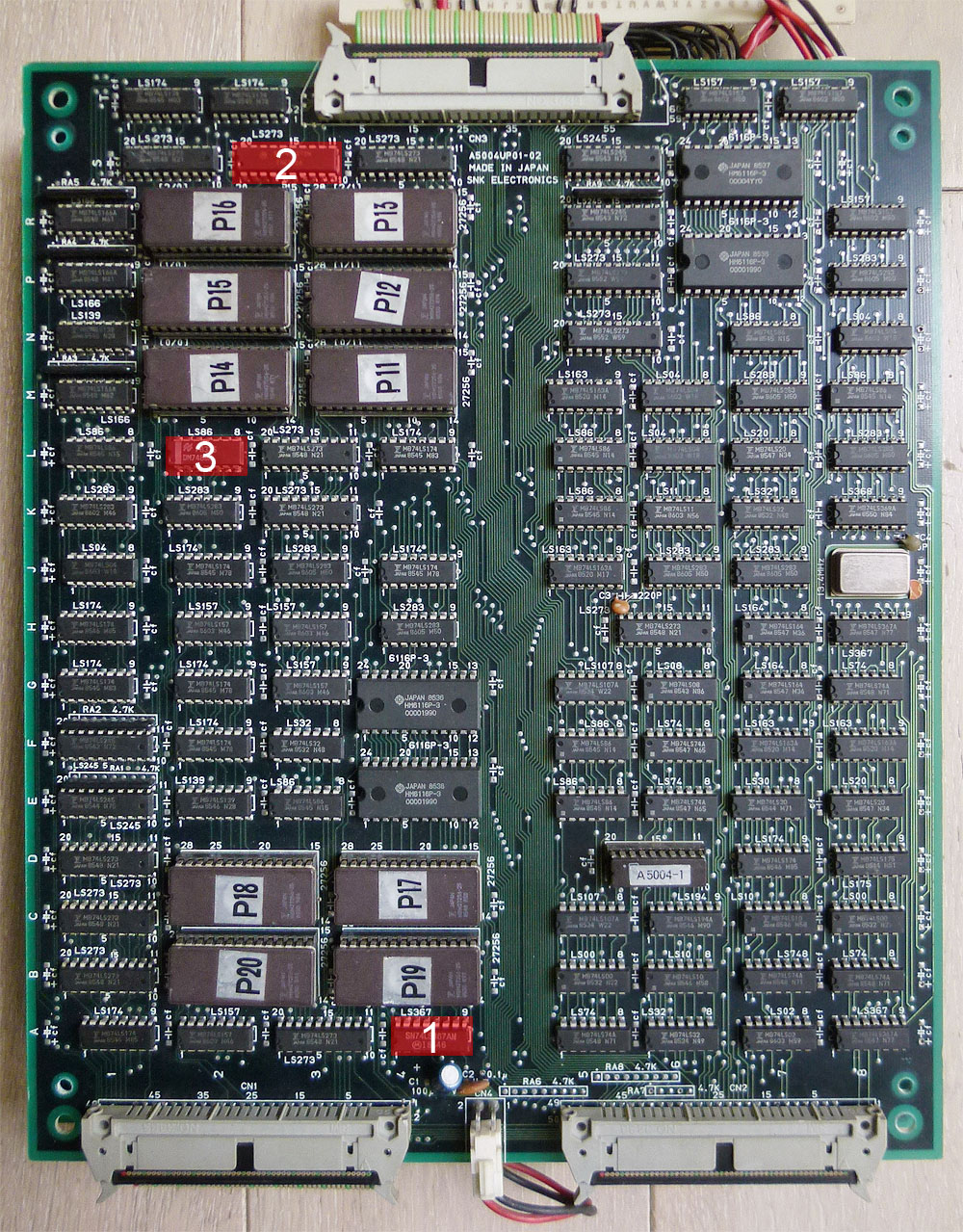
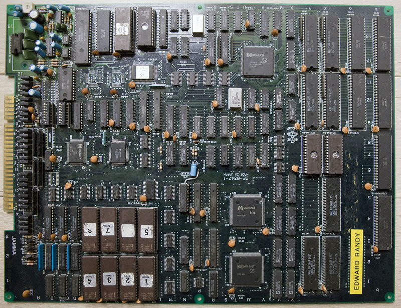
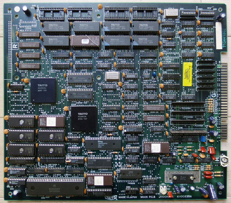
Here is a picture of my PCB with all the bad chips I replaced in red:

gryzor4b

Heavy Unit repair log #1

 PCB Repair Logs, Repair Logs  Comments Off on Heavy Unit repair log #1
Dec 142015
 

I got a dead Heavy Unit PCB with a white screen on boot:

hvyunit1

Looking at the MAME driver for that game I could see where the program roms were located (5C for the main program rom and 5P for the sub program rom).
I started probing around the CPUs and program roms. The CPUs (2 x Z80) seemed active and the program roms had pulsing signals on most of their pins. A few were inactive and connected to nearby GALs (labeled MD-500 and MD-501). All the I/O pins were stuck low on these two GALs while they had pulsing inputs.

There are 3 GALs in total on that board, MD-500 is connected to the main program rom, MD-501 is connected to the sub program rom and MD-502 is connected to the sound rom.
Surprisingly all these 3 GALs had inactive I/O pins. I got a working Heavy Unit PCB from a friend, compared the signals on the GALs and saw that almost every I/O pins were pulsing on the 3 GALs.

These GALs were not available online so I started desoldering them on both PCBs.
I put sockets on the dead PCB, socketed the GALs from the working board and the game booted ! …but with partially missing graphics (I had colored squares instead of sprites):

hvyunit2

Looking at the PCB I supposed the main program rom at 5C was not original as it had no label. Dumping it revealed it was from a US version. Looking at the MAME driver, I could see that every of the 4 versions dumped in MAME had a different ROM layout and my version was not dumped (the numbers on the labels were not in MAME). Particularly, there was a 512kb ROM at 2F on every versions in MAME that wasn’t soldered on my PCB, although I found its content spread on 4x128kb ROMs at other locations. The main program ROM was probably looking at the wrong location so I soldered a socket at 2F to put the 512kb ROM (from one of the MAME dumped versions and labeled B73_08) and the sprites were back. 🙂

hvyunit3

Here is my PCB with the added 512kb EPROM from MAME at 2F (equivalent to B73_17 + B73_18 + B73_19 + B73_20 on the left):

hvyunit0

ps: I’m still looking for the original program ROM for my PCB (labeled B73_24 and located at 5C) to be dumped so I could remove the 512kb at 2F and use the original 128kb ROMs already present on the board. I suppose it is a japanese version.

ps2: I wanted to dump the GALs from the working board but they were protected. To dump protected GALs I needed to use a method by Charles MacDonald. First, I used this adapter in order to read my GALs as 27C020 EPROMs: https://techno-junk.org/files/adapter-v2.png
Then, I used PD.EXE and WinCUPL to recreate the GALs from my raw dumps: https://dreamjam.co.uk/emuviews/readpal.php
These GALs are now available on https://www.jammarcade.net

Oct 232015
 

I recently repaired a friend’s dead Ikari Warriors PCB.

It had a black screen on boot with no sound.

This game is a bit tough to diagnose as it is composed of 3 PCBs mounted on each other. Fortunately I had another working Ikari Warriors PCB so I could swap boards in order to track which board(s) were faulty. Top board and middle board were tested ok on my working Ikari so, fortunately, only the bottom board was faulty.

Here is a picture of the faulty bottom board with the faulty chips I replaced in red. I’ll explain every step below.

ikari1b

1. There was something that was avoiding the game to boot on that board. First, in order to reduce the field of investigation, I disconnected each of the 3 connectors on my working Ikari to see when the game was booting or not. It was booting only with the two bottom connectors on, the one above is only related to the sprites and doesn’t prevent the game to run. So I needed to focus on and around these two bottom connectors. I checked the signals on every pins to track a possible missing signal. After comparing the signals, I found one that was “floating” on my faulty board and was pulsing on my working board. This was connected to pin 9 of the 74LS367 (marked 1 on the PCB picture). Piggybacking a working chip on that one bring the game booting back again !

2. Well, the game worked but the characters had missing legs and were always looking down whatever movement you did, enemies had wrong visuals and background scrolling was jerky…

As previously seen, the sprites are related to the upper connector. I started to check the signals on the upper part of the board and quickly found a 74LS273 (marked 2 on the PCB picture) with a seemingly dead output (my working board confirmed this). Piggybacking the chip with a new one bring back the characters’ movements and visuals. I still had the jerky scrolling though…

3. This one took a bit longer as I had no real idea where to look on the board for the chip that was responsible of this jerky scrolling. After more than an hour, comparing signals between the working and faulty boards, I found a suspicious signal on a 74LS86 (marked 3 on the PCB picture). This was indeed a dead output (pin 6). Piggybacking a good chip on it bring back the smooth scrolling.

As an example, here is what the signal looked like on the pin 6 of that 74LS86 before and after replacement.

ikari4

Board is now fully fixed.

Sep 042015
 

I got an Edward Randy with a black screen (but partial sound).

After a few checks with my scope, I quickly found a PAL @ location N5 with no signals on all of its outputs (BUT signals on its inputs).

edrandy1

As PALs from this game are not available yet online, I looked for other games that possibly shared the same hardware/system in order to try using a similar PAL.

And yes, that system is listed as “Data East Caveman Ninja Hardware” in MAME and some of these games got their PALs dumped. It was the case of Caveman Ninja and Robocop 2 that shares an almost identical PCB layout than Edward Randy (there are only a few differences in the GFX ROMs part).

So I burned the PAL at location N5 from Robocop 2 and plugged it on my Ed Randy board and here is what I got:

edrandy4

Well, at that time I was thinking it was due to an incompatibility between Robocop 2 and Edward Randy PALs and I temporarily gave up, waiting to get a dump from a working Edward Randy to be sure…

Then Shoestring confirmed me Caveman Ninja and Robocop 2 PALs @ N5 were strictly identical. It leaded him to believe that perhaps they are all common to each other and maybe there is a different problem with my board, which pushed me to have a look back at my board for possible other faulty chips. And he did well…

I started looking for other issues on the PCB and noticed that bending the board made the garbled graphics changing, even making them better looking at some point.
So I suspected the two SMC Data East customs labeled “55” having bad solder joints and reflowed the solder on them.

It then went way better. I had clean backgrounds in game, full intro with clean texts and pictures, title and Data East logo appearing (didn’t have all of that before) but no sprites in game. I noticed a square on the bottom-right corner that seemed containing garbled parts of sprites.

I then managed to find where the sprites part was located on the board and found two 6116 RAMs @ locations N9 and M9 that had suspicious signals on their data lines (pulsing but weakly and at low voltage). Piggybacking a known good working compatible RAM made parts of garbled sprites randomly appearing on screen.

I then desoldered one of the two RAMs (at location N9). With no big surprise it was tested bad on my programmer. I soldered a socket and put a new RAM in place. There was still no sprites but the garbled square on the bottom-right corner was not there anymore. Data lines on the new RAM were looking pretty much better though with strong pulses at 5V. The RAM located at M9 still showed weak outputs so I replaced it with another good known RAM:

edrandy6

Then sprites magically appeared !

edrandy5

Only one thing was remaining: the voice generating chips (2x OKI M6295) were missing so I replaced them and got the sound fully working.

I played the game several times since that and it is working perfectly.

Aug 302015
 

I bought a dead Rastan PCB for a fair price on a forum.

rastan1

All I got was a screen with garbled graphics on boot:

rastan2

Luckily, schematics are available online for this board. Anyway, I spent hours with my scope trying to find why there was no activity at all in the CPU area. I desoldered the two RAMs and the 68000 (all were tested OK as well as the ROMs).

Next, I desoldered the 2 PALs that are involved in the address decoding (labeled B04-09 @ IC11 and B04-10 @ IC12) in order to check them and finally discovered that B04-10 was slightly cracked (it is the one at the bottom-left corner of the board, you could figure it was heavily bended there) and, with no surprise, it couldn’t be read on my programmer. See the crack in the middle of the chip, it was unnoticeable before removal:

rastan5

Fortunately, PALs for this game are available on JAMMArcade.net so I took a blank GAL and burned the equivalent file but then got a black screen… Ok, that was my fault as the file was an untested dump from a PAL16L8 and needed to be converted to GAL16V8 in order to work properly. I did the conversion with PALTOGAL.EXE, reburned it then the game booted !

Great… But my enthusiasm quickly stopped as I noticed some issues:

1) The game sometimes crashed then rebooted, it happened 1/3 times when I started a game.

2) There was no sound (I could sometimes randomly hear a voice looping then fading away).

3) A few sprites were garbled.

It turned out that both issues 1) and 2) were related to a defective sound RAM chip @ IC50.

System11 reports the exact same problem on one of his Rastan repair logs (corrupted sound with main CPU crashing randomly due to a defective sound RAM).

This was not easy to troubleshoot because that RAM @ IC50 had seemingly “normal” pulsing signals on every pins and piggybacking didn’t worked at first. After reading that repair log from System11, I tried again piggybacking and that time it worked ! (well, it partially worked and not all the time)
So I’ve replaced the chip and got it working fine with sound and no freezes !

Only the issue 3) was remaining. The fault was most probably due to one of the gfx mask ROMs @ IC28 (1Mbit into a 28pins chip) that was replaced by an hacked 27C010 1Mbit 32pins EPROM. I could see things changing when touching a couple of pins on the EPROM. Here is a picture of it:

rastan3

I could replace this bad looking hacked EPROM with a blank TC531000, LH531000 or a HN62331 mask ROM as they seems to have the exact same specs and size than the original mask ROM but it seems nearly impossible to find these chips nowadays.

After comparing the pinouts between 1Mbit 32pins EPROM and 1Mbit 28pins MASK ROM I found what was missing on that hack: pin #2 (A16) of the EPROM was not going anywhere and it should be connected to pin #22 on the socket. I soldered a thin wire on the EPROM and plugged it underneath the chip on the socket.

Plugged back the chip and the gfx were then fully fixed ! (as an example, this axe on the bottom-right corner was garbled before):

rastan4

Alright, BUT… After playing the game for a few minutes, I noticed when dying that Rastan’s voice was suddenly cut and looped 3 times along with his jumping voice. If I had to replace what I heard with words that would make: DYING/cut/JUMPING/DYING/cut/JUMPING/DYING/cut.
Well, that sounded weird so a verification in the emulator confirmed that was not normal.

The test mode features a sound test so I compared all the voices between my board and the game in MAME and there was 3 voices replaced by this looping sound of Rastan’s dying/jumping.

Alright, had to look back at the schematics…

This was (most probably) related to the voice generating part which is pretty small fortunately as it involves only a few TTLs as well as the Z80, one EPROM and one M5205 (ADPCM sound generator).
Sound ROMs were tested OK and every address and data lines looked fine.

Checking the related TTLs with the scope, I noticed there was no pulsing signals on every of the 5 outputs of the 74LS193 @ IC60 while its inputs were pulsing. This chip is a counter and it is partially doing the link between the sound data bus and the voice address bus. There is another 74LS193 @ IC77 doing the same work for other address/data lines and outputs were pulsing when I pushed the button to generate one of Rastan’s voice in the sound test.

Piggybacking the chip at IC60 made the voices working fine with no weird loop. Also the other voices in the sound test were back. Replaced the chip and finally have now a perfectly working Rastan. (well, played it a few hours and it runs perfectly !)

Thanks to Porchy and Caius for their help on the PAL and hacked EPROM.