Mar 082018
 

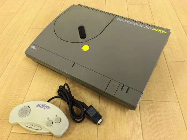
As many of you collectors/enthusiasts may know, the FM Towns Marty is  is a  home video game console released in 1993 by Fujitsu, exclusively for the Japanese market. It was the first 32-bit home video game system, and came complete with a built in CD-ROM drive and floppy disk drive (able to read 1.2MB formatted disk like other japanese systems). It was based on the earlier FM Towns computer system Fujitsu had released in 1989. The Marty was backward-compatible with older FM Towns games :


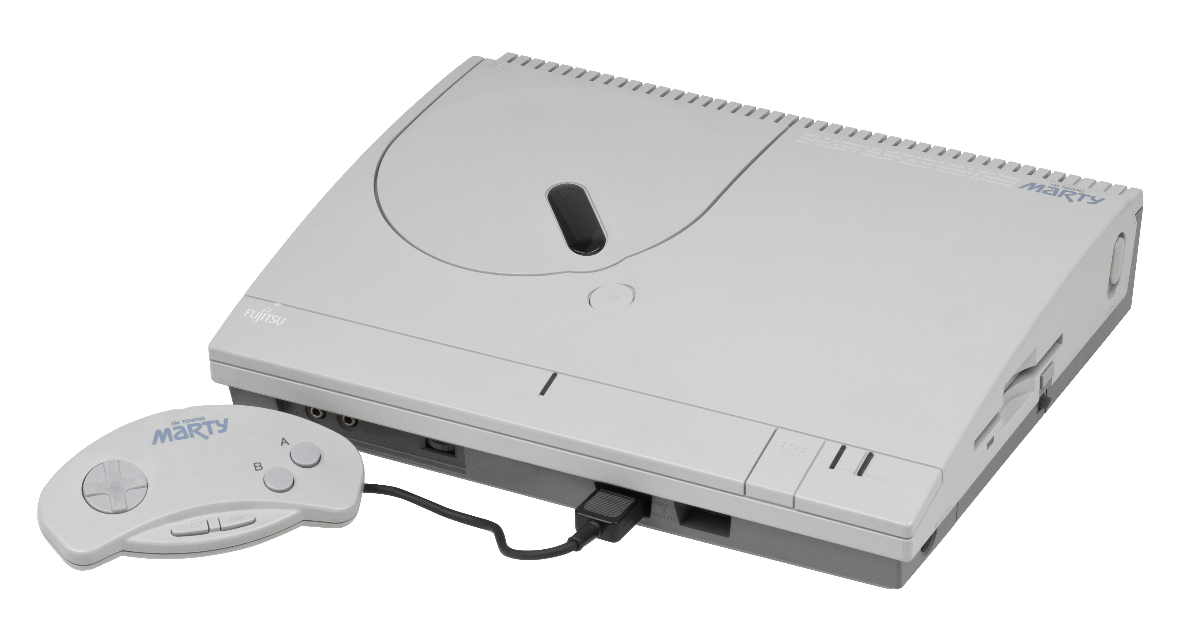
A later model called Marty 2 was released in 1994 but it was essentially the same hardware (darker grey shell apart)

Game list includes many Japanese versions of great PC games, such as Indiana Jones and the Fate of Atlantis, Wing Commander II, Ultima VI, Monkey Island II, and so on.But this console is well known also for having many arcade-perfect ports like Splatterhouse, Tatsujin Oh, Raiden, Super Street Fighter 2, Viewpoint and other.Most of its software is on bootable CD-ROM but some games require both a CD and a floppy disk, so even if a burned CDR is used, a correctly formatted floppy is also required.Sadly the floppy drive is a weak point of this console, in best of cases the drive belt may melt over time but the unit is considered fragile and no spare are available.Luckily nowadays FDDs can be replaced by emulator and in this article I will explain how to use an HxC SD floppy emulator (by Jean-Francois del Nero) in a Marty (or Marty 2 like mine) console.

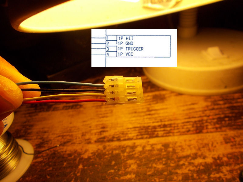
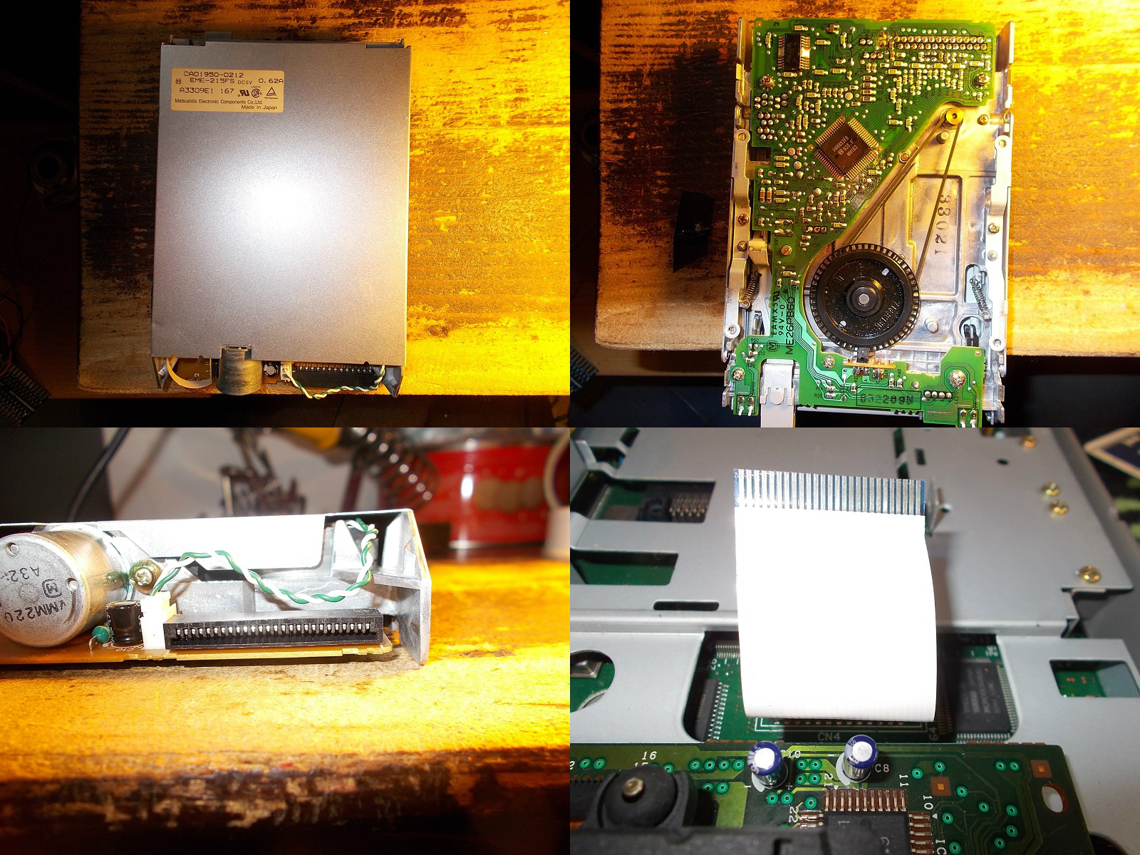
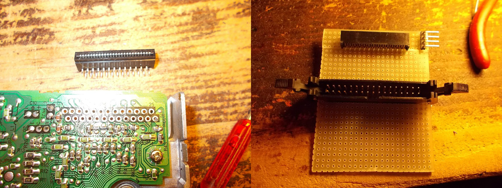
The original FDD of the FM Towns Marty console is a EME-215FS manufactured by Matsushita with a 26PIN FFC connector and cable (1.25mm of pitch) :

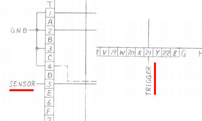
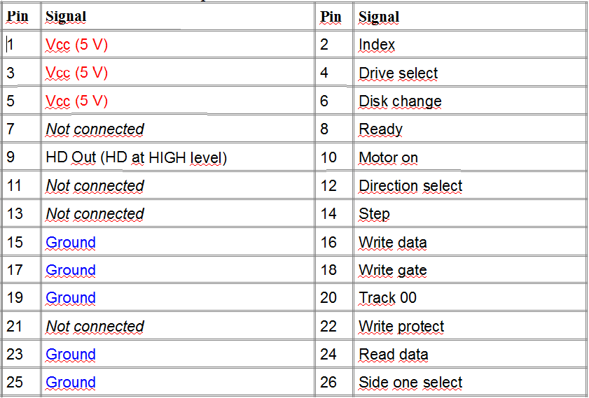
No info were available about so I first analized it and came to the conclusion that its pinout was the same of a slim 26PIN FDD for PC which comes with a FFC connector too but pitch is 1.00mm ( pin 13 and 21 are GND on Marty)

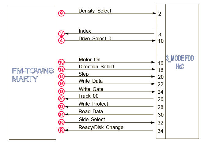
Based on the above pinout I figured out the connection diagram to the HxC (or a real 34 pin FDD able to handle 1.2MB formatted disks)

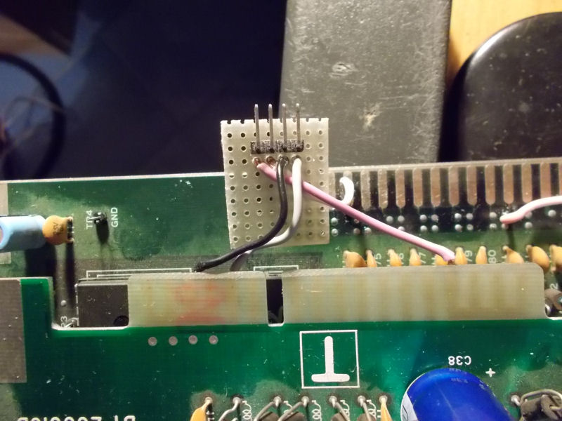
Obviously some kind of adapter was needed.Not having a spare 1.25mm FFC connector I ended up to remove the one from original drive and build an adapter to 34 PIN IDC (the 4 pin connector is for powering the HxC) :

I carried on the first test on a Samsung SFD-321B FDD (modified to work as Shugart drive) and it worked, I  was able to read/write/format 1.2MB 3.5″ floppies :

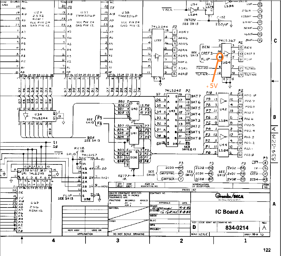
But I was not able to do the same with the HC floppy emulator.After some emails exchanged with Jean-Francois del Nero (a.k.a. Jeff, the designer of the HxC) we found the issue.The READ DATA signal (output from pin 30 of the HxC) was quite slow to rise up in his opinion:

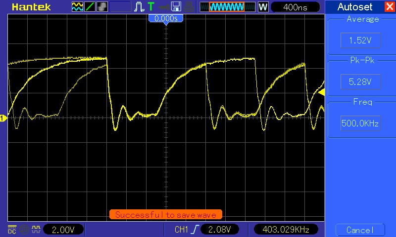
He suggested me to install a 220 Ohm pull-up resistor between pin 30 and +5V (actually FDD outputs are already pulled-up with 2.2K resistors so a further 220 Ohm one put in parallel lowers the resistance to VCC to about 200 Ohm).This corrected the signal to what Marty expected to see:

Doing so finally I got the HxC flopy emulator working with my Marty console!Here are a couple of video I made during reading and formatting operation (sorry for black&white picture but my TV cannot accept NTSC signal)


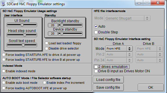
As for the HxC configuration file you can set the interface on “Auto” or ” Generic Shugart” and all other settings on “From HFE”

A big thanks again to Jeff for his wonderful device and support (and patience with me too..).

 Posted by at 3:48 pm

How to use JEDutil

 Guides  Comments Off on How to use JEDutil
Apr 292017
 

JEDutil is a program included with MAME.
While MAME doesn’t directly use PAL dumps for emulation it does look to load them if they are available. As each programmer has its own output format when reading these chips (some are really different, other not so much) there arose the need to have a standard.
Read here for more information

What can JEDutil do?

It can convert a programmer usable .jed file to a MAME usable .bin file
It can convert from the MAME usable .bin file back to a programmer usable .jed file
It can be used to view the equations of any support .jed or.bin file

To see a list of supported devices you use the “-viewlist” argument

To view equations use the “-view” argument

These equations show exactly how the outputs works in relation to any given input and I believe is self explanatory to those who are looking.
Here is what the file im using for this example looks like in a text editor

You can clearly see it was created using WinCUPL.

Here is what a JEDutil created .jed file will look like opened up in a text editor

It looks very similar to the WinCUPL created file and most programmers i’ve encountered can load these without issue. One exception to that (and there are certainly others too) is the Needham EMP-20 which seems to use its own binary format that is not compatible with the MAME format.

Here is what a MAME usable binary file for a .jed will look like in a hex editor

There are clear difference between the binary and jedec files and should be easy to spot if you are not 100% sure what you have got.

Converting a MAME binary to a Jedec file
If you want to use the PAL dumps found in MAME on real hardware then you MUST convert them from their binary format back into .jed format.
You need to use the “-convert” argument

Note the filename extensions used here. The output file must be .jed (or .pla) or the conversion will fail and you will see this useful message

Converting a Jedec file to a MAME binary
To convert a .jed file into a MAME .bin file you simply use the same command but swap the filename extensions.

This will create the binary file. The original .jed file will remain untouched.

The only time I can really think of anyone needing to convert to a MAME binary is if you are submitting your dumps for inclusion to MAME
I’ve yet to ever find a use for the Berkeley PLA conversion so I haven’t covered it in here but if required it should be straight forward enough to work out.

Other Errors
Occasionally you might see some more cryptic error messages when using JEDutil. While there are things you can do to try and get around these they might also be a sign of a corrupt file or one of incorrect format.
The Jedec file format has two checksums both found at the end of the file.
The first is the fusemap checksum and the second is the transmission checksum

In the example used above the fusemap checksum is “3E71”. I believe the “C” part is always present.
The transmission checksum is “D5F0”

The fusemap checksum is the 16bit sum of all the 8bit fuse values.
The transmission checksum is a little more. Using the same example as before

The transmission checksum is a 16 bit sum of all the ASCII characters between (and including) the STX and ETX markers.

If the fusemap checksum if incorrect but the transmission checksum is correct then you will get this message

If the transmission checksum is incorrect then you will get this message

I believe you will get this message even if there is a fusemap checksum error as well.
You can disable the transmission checksum by changing it to “0000”.

In the past if I got stuck working with a strange .jed file I have loaded it into my programmers software and saved it back. This rewrites all the checksums to be correct. Your milage may vary!

There may be other errors, maybe not. I’ve not come across any other to really bother myself about.

 Posted by at 3:03 pm

ROM dumping and checking

 Guides  Comments Off on ROM dumping and checking
May 292016
 

There has been a fair bit of discussion going on in the background recently about how is best to dump ROM’s from a PCB.
This has mainly been centered around dumping with the intent of submitting them for inclusion into MAME but this still applies if you are dumping for your own reasons too.

Obviously the first thing that you need is an EPROM programmer of some kind. The selection available is massive and not really a topic this post will delve into too much.
I myself have 3 programmers available to use.
My main workhorse is a Dataman 48pro2. Its been fantastic ever since I bought it and the support is top notch too. The downside of this programmer is the cost.
My second programmer is a cheap generic Chinese programmer. The software is not too great and the English translation isn’t all that great either but it does the job nicely when my main programmer complains about voltages being out of spec or whatever.
My last programmer is a Needham EMP-20 (actually have two of these). I was given these from a local company that was having a clear out of their old unused equipment. They are really good but their downside is they are parallel port only and the software is DOS based. Apart from that they both work well.

So how do we dump ROM’s?
At first glance we think it isn’t much more than removing an EPROM from a PCB, fitting it into the programmer socket, selecting the correct device and clicking ‘READ’ in the software.
A lot of the time this is fine but how do we do our best to know that the dump was good? What if one of those old thin crusty legs on the EPROM doesn’t make a good connection throughout the read?
The result of the read under these circumstances will be, quite simply put, a useless dump of that EPROM.
Lets look at this a bit more. Say you are dumping with the view of submitting to MAME. You dump the ROM(s), bundle it up in a zip file and send it off.
Then one of the developers takes the time to add it to the source code and do some testing. Now lets say the game doesn’t work or some of the graphics are messed up.
In some circumstances, say for instance the game was a prototype or something, that developer or developers starts looking for errors either in ROM dumps or the emulation itself. Before you know it he/she has invested a few hours of their time.

The other scenario. You dump the EPROM for your own purposes. Some days, weeks, months or years down the line you need to program yourself a new EPROM because the old one has died or suffered from bitrot. You program it up and fit it but it doesn’t work. Is there something else wrong with your PCB? But what if you just didn’t dump it correctly in the first place and you never realised. You never made the dump public so any potential testers out there couldn’t even do the testing on your behalf and notify you. Congratulations, you’ve now got a useless piece of electronics on your hands.

Either way your dump was bad but we could have potentially avoided this whole mess by carrying out some really easy checks. Lets look at it.
When dumping a ROM we want to be extra sure that every time we read the device we get the same data. Every programmer I’ve ever used will display a checksum of the data dumped (although YMMV) like this.
checksum

If you read the device a second time and the checksum is different from the first time then we clearly have an issue but what if it’s the same every time? The data could still be bad so let’s try physically removing the device from the programmer and reinserting it then trying to read it again. Is the checksum still the same? If not then we are probably going to need to investigate further. If they are the same then how about we remove and reseat one more time just to be sure. This may sound like a waste of time but the reality of it is it only takes a few seconds for older EPROM’s to be read out and it could potentially save everyone a lot headache further down the line.

So now we have dumped the ROM (three times) and we are happy that no matter what we do or how we position it in our programmers we get the same dump each and every time. What next?
In the case of an arcade PCB let see if the dump we have compares to anything already dumped and included in MAME.
For this you will need the latest version of MAME available from MAMEDEV
Open a command prompt at the directory where you unzipped/installed MAME and type ‘mame -romident [YOUR-ZIPPED-FILES-LOCATION]’. If you use the 64bit version then type ‘mame64 -romident [YOUR-ZIPPED-FILES-LOCATION]’ instead.

Here is an example using the rbisland romset. I’ve added a random binary file to show what happens when an undumped file is found.
romident

What this shows is each individual file within the .zip file and the filename associated with each other romset.
The “9100.bin” file is the undumped file and you can see it shows “NO MATCH”. This means that the file is unknown to MAME.

If they are all matched then nothing more needs to be done. If they aren’t a match though then we could be looking at something undumped OR we could still be looking at a bad dump.

Included in the MAME package is a tool called ‘ROMCMP.EXE’. This is another command line utility that performs a variety of checks on your files. For example it will tell you if the dump is all 0xFF bytes or if the top and bottom half of the dump are the same. It can also be used to compare your files against the files currently in MAME to see how much of the data matches.

To use this tool we need our file or files in a .ZIP file.
For this example I( have used the Major Title 2 romset ZIP file and have added an extra binary file which I hand made but made bit 1 (second bit) stuck on using a hex editor.
romcmp

The output is simple enough to see. It shows that bit 1 is always ‘1’.
If you have dumped what you believe is a new ROM set then you can use ROMCMP to compare against an existing set.

Here I used two different sets of Major Title 2 to demonstrate.
romcmp2

You can see most files are identical but there are two that aren’t quite the same (these two are the main program ROM’s for Major Title 2). You can also see that they are both over 80% the same as each other. This is a good sign for a different revision of the same game especially as we have already done the previous checks on the ROM’s to confirm their validity as much as possible.

There may be other steps that people like to do on their ROM dumps but the above will give people, whether its yourself or an emulator developer trying to support it, a fighting chance.

 Posted by at 12:20 pm

Using a lightgun with Operation Wolf PCB

 Guides  Comments Off on Using a lightgun with Operation Wolf PCB
Apr 052016
 

Some days ago I received an Operation Wolf PCB bought from Hungary.After dumped ROMs and comparing the board layout with pictures on the web it turned out to be a rare prototype which runs unprotected code (it lacks of the C-CHIP IC).I suggest you to read the whole story on David ‘Haze Haywood ‘ homepage:

A Wolf in Prototype Clothing

After adapting the board to JAMMA, I fired it up and it was perfectly working.Reading on the Web,  there are conflicting opinions if this board is a simpe lightgun game or it uses analog joystick like some many people claim.So I wanted to try myself and bought a couple of cheap Happ lightguns widely used on games like Lethal Enforcers :

happ_gun

All lightguns work in the same way: you’re pointing your gun at the screen, and the gun is essentially a light sensor.When the part of the screen which the gun is pointing at gets flooded in white, the sensor detects it and sends a signal to the game: “I can see white now, I’m pointing at the part of the screen you’ve just drawn”. At this point the game can work out how far down the screen it has drawn, and how far along the current line, which gives a pretty accurate position of where the gun is pointing.

The Happ gun has a 4 PIN connector and looking at Lethal Enforcers schematics, this is the pinout:

happ_gun_connector

The ‘HIT’ signal (so called in Lethal Enforcers but name is relative) is an input on arcade PCBs and it’s essentially the output of the optical sensor (a phototransistor) mounted inside the gun.The ‘TRIGGER’ is the switch inside the gun and it’s shorted to GND everytime, indeed, you pull the trigger.VCC and GND are obviously needed to power the electronics inside the gun.With this info it was very simple to adapt this gun to the Operation Wolf PCB.The pinout of this board shows ‘TRIGGER’ signal on pin 21 parst side of ‘G’ edge connector on main board and ‘HIT’ (called ‘SENSOR’ in service manual) on pin 5 solder side of the ‘T’ edge connector on sound board:

SENSOR_TRRIGGER

For a better interfacing of the gun to the PCB I used a 4 pin right-angle male header mounted on a piece of veroboard:

4_pin_header_Operation_Wolf

Lastly, since Operation Wolf use another input for rocket and this Happ gun lack of a second switch, I added a further button (a normally-open one)  mounted inside the gun and connected to internal common GND and ‘ROCKET’ signal which is PIN 4 of the ‘M’ connector on Operation Wolf main board (but if you want, you can also adapt a PSX/Saturn Guncon which comes with more than a button)

rocket_switch


M_connector_pinout

Finally now for sure I can say that Operation Wolf is a simple lightgun game.So let’s go to play it!

 Posted by at 11:33 pm
Mar 292016
 

Sometimes it is very annoying when you have placed your arcade monitor vertically and certain games are shown upside down and  even worse they have no option to flip the screen.

It happens very often with older games but sometimes even with newer games from the 90s.

In these cases you have 2 options: reverse phisically your monitor or reverse the yoke  on the pcb of the monitor (not very safe).

Now I show you a new option available only when the games were also prepared for cocktail tables (that means they have already the circuit to flip the screen for the second player)

In this first “flip screen” hack I will take Zaxxon / Future Spy hardware as an example


Future Spy_2

These games have no flip screen option but they have the preparation for cocktail tables play.

The board is very big but luckily schematics are available and they are very clear to understand.

The hack is very simple: input nr.4 of 74ls367@U64  is normally LOW for first player game and HI for second player game.

We have only to force pin 4 to HI (+5V) using a wire so that the screen is always flipped as it was playing the second player even in upright mode.

Zaxxo_flip screen hack


FS


Very simple and effective!