Jan 032016
 

Contra / Gryzor shares almost the same hardware specs with Combat School / Boot Camp, Fast Lane, Flak Attack / MX5000, Haunted Castle / Akumajô Dracula and Trick Trap / Labyrinth Runner.

But among these titles, it is the only game that offers a stereo output thru a 4-pin connector on the board (labeled CN2).

First, you have to select stereo by plugging a connector on CN4 (and put switch 4 of DIPSW3 to off).

contra-sound

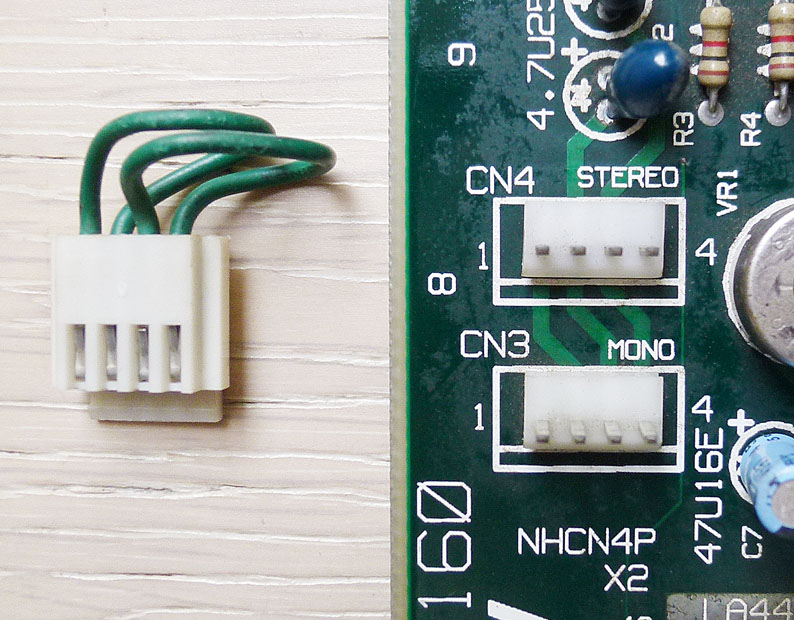
The thing is that all the boards I’ve seen still delivers mono sound when you plug this connector (originally brought by Konami and present on the board) on the stereo plug. Why ? Because it doesn’t have the good wiring…

As shown on the picture above, this connector originally comes with pin #1 wired to #2 and pin #3 wired to #4. In that way and plugged on the stereo connector (CN4), it mixes channel 1 and channel 2 from the YM3012 DAC to the LA4445 amp which results a mono output.

To separate the channels, you have to simply modify the connector by wiring pin #1 to #3 and pin #2 to #4.
Now plug it on CN4 and enjoy stereo sound out of CN2. 🙂

There are other Konami games that use the same connector to choose mono or stereo. I’m not sure about the wiring for every game. To my knowledge they are:

Salamander
– Jackal / Top Gunner
Devil World / Dark Adventure
– Gradius II / Vulcan Venture

– Ajax

Lightning Fighters / Trigon (stereo works without modification of the connector)
– Parodius
(stereo works without modification of the connector)
Surprise Attack (that game seems to have a mono sound design, despite the stereo connector present on the board)

ps. If anybody knows if the original wiring on these boards allows to deliver stereo sound or any other board that is using this connector, I would be glad to know and add it here.

Using the HxC Floppy Emulator with a Fluke 9100

 Guides  Comments Off on Using the HxC Floppy Emulator with a Fluke 9100
Jul 192015
 

Recently the floppy drive on my Fluke 9100 became unusable and I feared the worst. I’ve tried once before to get the HxC floppy drive emulator to work with this but I never managed and to be honest I’ve never delved into floppy drives at all so I was a bit clueless.

I found THIS site while looking for information and at first I skimmed over the details and didn’t really take any of it in. That was a big mistake as it provided all the information I needed to get this up and running.

The only thing I needed to do on the hardware side of things was to cut pin 14 of the floppy cable and connect the Fluke 9100 side to GND.
Everything else is all software.
In the HxC Floppy Emulator software you need to apply these settings
settings

Save the config file to the SD card.

Then “Load” the .TD0 files that are available from HERE or HERE.

The HxC software can deal with these files without any issue so once you have loaded one go ahead and “Export” it to your SD card using the indexing naming scheme
Disk 1 = DSKA0000.HFE
Disk 2 = DSKA0001.HFE
etc

I have the first dip set to ON on the HxC device.
Once that’s all done you can fire up the Fluke and use your SD card to load.
My Fluke doesn’t have an SCSI controller hence it has no hard drive fitted so it is vital I have a working floppy drive.

Once you have the OS loaded up from the floppy drive you may need to change the way the system loads the user disks.
If your system is configured to be a 9100 then user disks are defaulted to load from the hard disk.
If your system is configured to be a 9105 the user disks are attempted to be loaded from the second floppy disk drive.

The HxC floppy replacement can apparently be configured to emulate two drives but I cannot for the life of me get it to work so this is necessary for me.

When loaded you will be met with this message
20160309_195246

Press the ‘SETUP’ button
20160309_195256

Move RIGHT to highlight ‘POD’
20160309_195304

Press F2 (‘USERDISK’) then select ‘DR1’. This is the first floppy drive.
20160309_195319

Go back to the initial ‘SETUP’ menu and select ‘POD’ again
20160309_195344

Then press the ‘SOFT KEYS’ button and some more options will appear
20160309_195349

Select ‘PODNAME’ and you will get this (Z80 pod is used here)
20160309_195354

Make sure you have the correct disk image selected on the HxC then press the ‘ENTER/YES’ key.
If all goes well the floppy will read and you will be presented with a new message (its different depending on POD type fitted)
20160309_195459

Now the POD is available to use.
NOTE: If you press the ‘RESET’ button on the keypad at anytime then it will revert back to DR2.

May 032015
 

Do you have an oscilloscope and you never use it?Don’t sell it, now I will explain how to turn it into a simple but effective component tester.

The name “Octopus” maybe doesn’t say anything alone but if you google it along the words “curve tracer” you will obtain thousands of result.In few words an “Octopus” curve tracer is a small circuit that used in conjunction with a scope allows to display  the voltage across a component under test on horizontal (X) axis versus the current through that component on the vertical (Y) axis.A scope set to X-Y mode is required (most of them have this feature).

There are lot of variants of “Octopus” circuit, personally I choose this one:

since it applies small voltage (less than 1VAC) and current (less than 1mA) allowing to test unpowered components also in circuit without risk of damaging them.

As you can from picture above circuit is made of very few common parts : there is a transformer 120VAC to 6.3VAC ( I’m in Europe so I used a 220VAC one), three resistors (the 560 Ohm and 100 Ohm ones forms a voltage divider to obtain 1VAC , then the 1KOhm one limits current to 1mA) and two probes.

This   circuit will produce a “signature” waveform on the oscilloscope to aid in the testing and analysis of shorts, opens, and leakage in just about any electronic component including resistors, capacitors, inductors, diodes,transistors and digital ICs too.Each component has a characteristic waveform (called “Lissajous” pattern), some examples:

Now, you will wondering what this device has to do with arcade?Well, personally I find it very uself  when I probe ICs out of circuit.For example, in my last repair I was unsure if a 74LS367 was good or not since I got discordant results from my testers.Probing it with the curve tracer and comparing its patterns with the ones of a good known IC removed all doubts:

74LS367_comparing

On the right the pattern generated from a good IC (74LS367), on the left the one from the defective one.Specifically you can see how the junction (internally a TTL contains transistors) of an output (PIN9) is weakened compared to the good one (pattern doesn’t have the healthy ‘L’ shape of a good diode/base to collector junction)

Obviously this curve tracer can be used also to test components in-circuit (thanks to the low voltage/current applied) but in this case experience is needed as components can interact each other producing misleading results.The best option would be having a good board as reference.

If you want to read more about, I recommend you this document:

https://www.qsl.net/kd7rem/pdf/octopus.pdf

So, what are you waiting for?Go and build your “Octopus”! 🙂

 Posted by at 11:36 pm

Programming a Timekeeper RAM with Arduino MEGA

 Arduino, Guides  Comments Off on Programming a Timekeeper RAM with Arduino MEGA
Apr 062015
 

There is a lot of people out there that need to program a Timekeeper RAM but don’t have the necessary hardware to do so.
Silent Scope 1 & 2 both use one of these and if it dies will display the infamous 11P error.

Recently I decided it would be good to write an Arduino program to do this job.
I have only tested this on an M48Z58Y chip which is almost identical to the M48T58Y only the later has an extra CE (active HIGH) line.
While this worked well for me on the former, it may have issues that need addressed. I have also NOT tested this in any Silent Scope hardware. While the correct data was programmed I have no idea if Silent Scope requires any of the extended functions the Timekeeper RAM offers.
To put it bluntly, this may or may not work for you. If it doesn’t then I have no real way of testing how to make it work with the hardware.

Its a pretty rough program and it is more of a proof of concept than a finished product. Hopefully it will be a starting point for someone to finish or rewrite it.
IMAG1227

The basic setup requires:
-Arduino MEGA 2560
-SD card breakout board
-Timekeeper RAM
-A valid NVRAM dump (named as “nvram.bin” in the root directory of the SD card)

I Wired up the connections as follows:

ARDUINO -> Timekeeper
38 -> A0
36 -> A1
34 -> A2
32 -> A3
30 -> A4
28 -> A5
26 -> A6
24 -> A7
25 -> A8
27 -> A9
33 -> A10
29 -> A11
22 -> A11

40 -> D0
42 -> D1
44 -> D2
45 -> D3
43 -> D4
41 -> D5
39 -> D6
37 -> D7

23 -> /WE
35 -> /CE1
46 -> CE2
31 -> /OE

The SD card was wired as follows:
53 -> CS
52 -> SCK
51 -> SI
50 -> SO

Don’t forget to wire up you VCC and GND for both of these too.
All these pin assignments can easily be changed in the program if you wish.

Once the ‘sketch’ has been loaded up from the IDE if you open the terminal window (9600 baud) and everything is configured correctly you should see the following text.
ssprog

Send an upper case S and a few seconds later it will hopefully have finished and the chip should be programmed.
The ‘sketch’ can be found in the Arduino download section.

 Posted by at 2:56 pm

Namco System 1 custom ’64A1′ replacement

 Guides  Comments Off on Namco System 1 custom ’64A1′ replacement
Mar 072015
 

First of all I want to thank JROK for providing me all the technical info and allowing its public release, without his help I would not have ever made.Let’s start with the story.

Some time ago a  friend of mine sent me his Splatterhouse PCB bought as working saying it got stuck upon boot  on ‘ROM TEST START!! PLEASE WAIT..’ message displayed upside down on a screen filled with red zero.So I started to investigate on the net and found that usually this kind of issues are caused by a faulty custom chip marked ’64A1′ @M4 on ROM board.This was confirmed by swapping this IC in another CPU board of Galaga88 with this missing component , in this case I got an ‘EEPROM ERROR’ message which is a further proof of the fault.

Thanks always to JROK we know that this ’64A1′ custom IC is nothing else than a HD63701 MCU with the exception of two custom opcodes not present in original part.You can go deeper into technical reading here:

https://www.jrok.com/hardware/cus60/cus60_an_owners_guide.html

So, programming a blank HD63701 MCU with the available dump from MAME won’t work due the presence of these two custom opcodes.So, patching a ROM is needed.

In the specific you have to change three bytes in the ROM  “VOICE0” at a specific offset.For example :  in Splatterhouse the offset is $FA8B and the new HEX values are “20 01 56”.

The string to search for in HEX is  “B7 C0 00 6E 00” and the first 3 bytes must be changed to  “20 01 56”

The patch seems to be needed at offset $FA8B for most games, but not all. Here’s a reference table :

PacMania -$FA8B
Tank Force – $FA29
Blazer – $FA8B
Dragon Spirit – $FA8B
Galaga 88 – $FA8B
Marchen Maze – $FA8B
Splatterhouse -$FA8B
Rompers – $FA8B
Blast Off – $FA8B
World Court – $FA8B
World Stadium (and WS ’89, WS ’90) – $FA8B
Bakutotsu Kijuutei (Baraduke 2) – $FA8B
Beraboh Man – $FA4E
Dangerous Seed – $FA8B
Face Off – $FA29
Pisto Daimyo no Bouken – $FA8B
Puzzle Club – no voice ROM !
Quester – $FA1B
Souko Ban Deluxe / Boxy Boy – $FA8B
Yokai Douchuuki (Shadowland) – $FA8B

So, it was only matter to find some real blank HD63701.My first attempt failed since I bought as new some ICs that they turned out to be already programmed and, since they were the plastic HD637B01VOP one-time-progfammable version, they were unusable for my purpose.But then I was luck and found some HD63701VOC UV erasable ones:

HD63701VOC

So, it was only matter to program one of these MCU with MAME dump using my Hi-Lo Systems ALL-11C EPROM programmer and, at the same time, replace the ROM ‘VOICE0’ with the properly patched one.Once done, I had confirmation of what the good JROK said about. Operation  ‘NAMCO custom 64A1 replacement’ accomplished.

 Posted by at 10:57 am