Namco System 1 custom ’64A1′ replacement

 Guides  Comments Off on Namco System 1 custom ’64A1′ replacement
Mar 072015
 

First of all I want to thank JROK for providing me all the technical info and allowing its public release, without his help I would not have ever made.Let’s start with the story.

Some time ago a  friend of mine sent me his Splatterhouse PCB bought as working saying it got stuck upon boot  on ‘ROM TEST START!! PLEASE WAIT..’ message displayed upside down on a screen filled with red zero.So I started to investigate on the net and found that usually this kind of issues are caused by a faulty custom chip marked ’64A1′ @M4 on ROM board.This was confirmed by swapping this IC in another CPU board of Galaga88 with this missing component , in this case I got an ‘EEPROM ERROR’ message which is a further proof of the fault.

Thanks always to JROK we know that this ’64A1′ custom IC is nothing else than a HD63701 MCU with the exception of two custom opcodes not present in original part.You can go deeper into technical reading here:

https://www.jrok.com/hardware/cus60/cus60_an_owners_guide.html

So, programming a blank HD63701 MCU with the available dump from MAME won’t work due the presence of these two custom opcodes.So, patching a ROM is needed.

In the specific you have to change three bytes in the ROM  “VOICE0” at a specific offset.For example :  in Splatterhouse the offset is $FA8B and the new HEX values are “20 01 56”.

The string to search for in HEX is  “B7 C0 00 6E 00” and the first 3 bytes must be changed to  “20 01 56”

The patch seems to be needed at offset $FA8B for most games, but not all. Here’s a reference table :

PacMania -$FA8B
Tank Force – $FA29
Blazer – $FA8B
Dragon Spirit – $FA8B
Galaga 88 – $FA8B
Marchen Maze – $FA8B
Splatterhouse -$FA8B
Rompers – $FA8B
Blast Off – $FA8B
World Court – $FA8B
World Stadium (and WS ’89, WS ’90) – $FA8B
Bakutotsu Kijuutei (Baraduke 2) – $FA8B
Beraboh Man – $FA4E
Dangerous Seed – $FA8B
Face Off – $FA29
Pisto Daimyo no Bouken – $FA8B
Puzzle Club – no voice ROM !
Quester – $FA1B
Souko Ban Deluxe / Boxy Boy – $FA8B
Yokai Douchuuki (Shadowland) – $FA8B

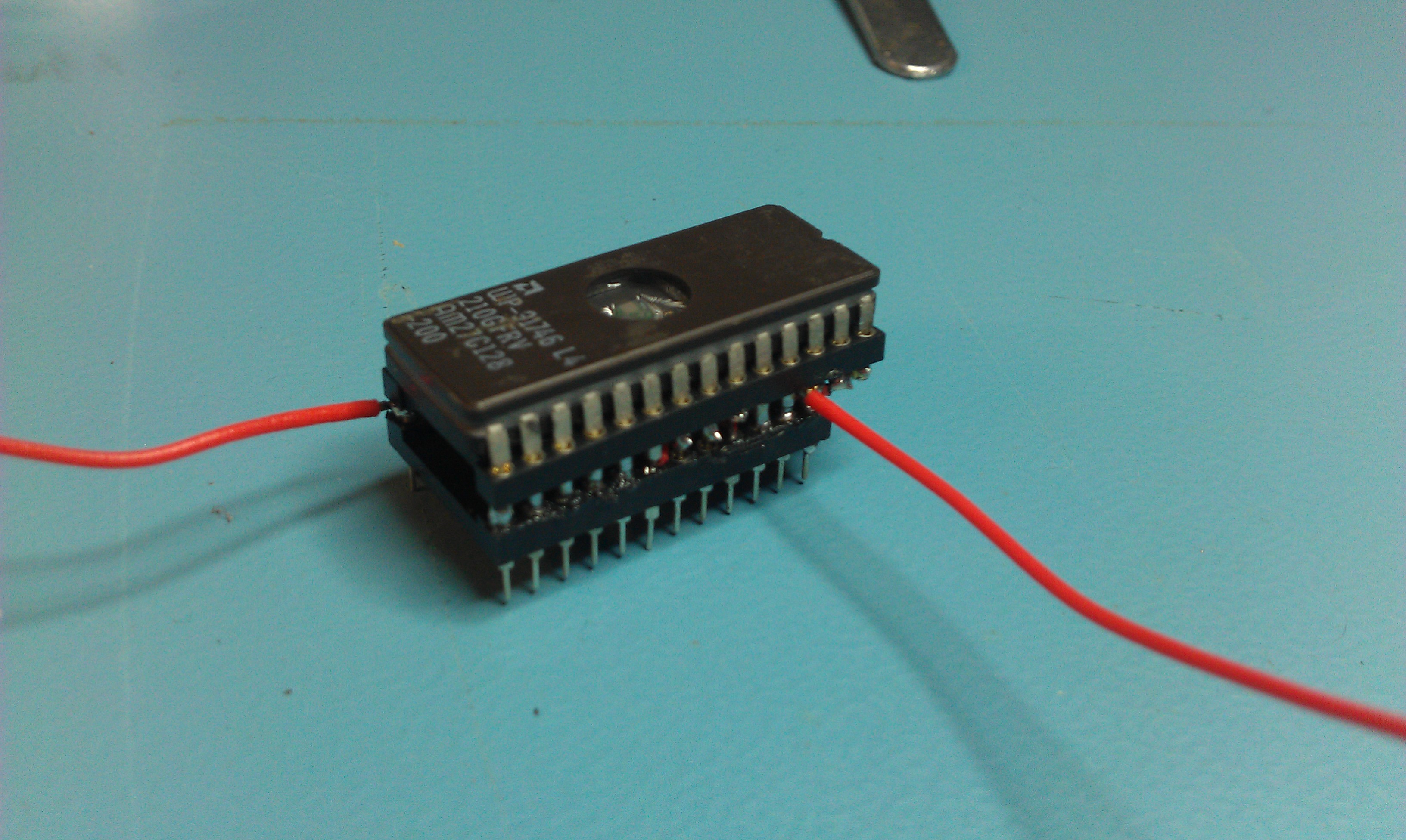
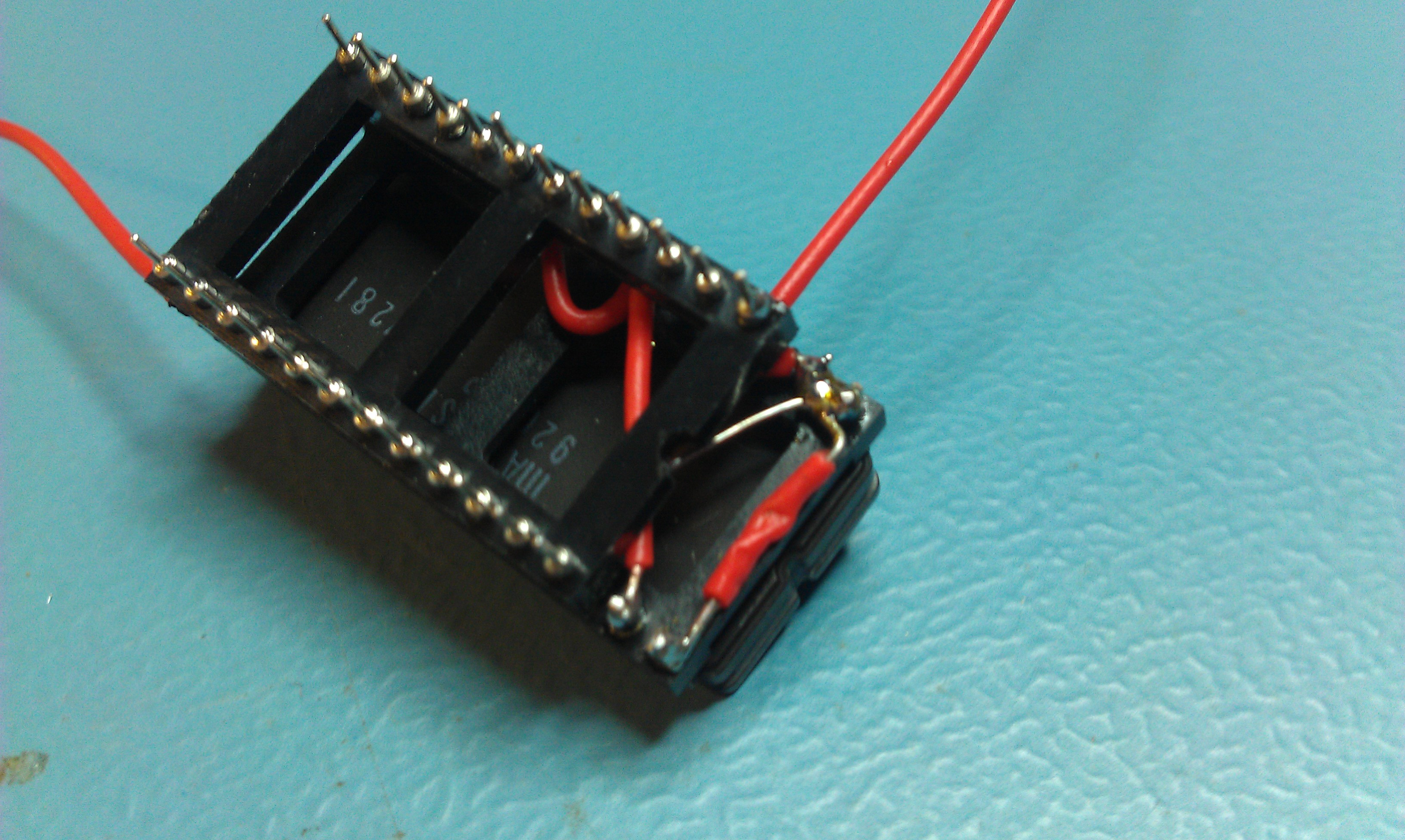
So, it was only matter to find some real blank HD63701.My first attempt failed since I bought as new some ICs that they turned out to be already programmed and, since they were the plastic HD637B01VOP one-time-progfammable version, they were unusable for my purpose.But then I was luck and found some HD63701VOC UV erasable ones:

HD63701VOC

So, it was only matter to program one of these MCU with MAME dump using my Hi-Lo Systems ALL-11C EPROM programmer and, at the same time, replace the ROM ‘VOICE0’ with the properly patched one.Once done, I had confirmation of what the good JROK said about. Operation  ‘NAMCO custom 64A1 replacement’ accomplished.

 Posted by at 10:57 am

Testing Bubble Bobble ROM banks with Fluke 9010

 Guides  Comments Off on Testing Bubble Bobble ROM banks with Fluke 9010
Nov 012014
 

Recently I was talking to IronGiant about testing the “a78-05-1.52” ROM on an original Bubble Bobble PCB with the Fluke 9010.
As the ROM is banked we cannot test this ROM in one go.
Here is how we managed to do it.

0) Before we do anything we need to disable the watchdog otherwise this wont work properly. This is done by cutting the track on JP6 on the solder side (thanks to IronGiant for the info).

1) Take the ROM dump for “a78-05-1.52” and split it into 4 files using a HEX editor or similar. Each file should be 0x4000 bytes in size.
Run all 4 files through one of the signature calculators that can be found online and make a note of them.

2) The bankswitch lies at address 0xFB40 in the address map.
You need to write a value between 4 and 7 to select the relevant bank.
So start by writing 4 to address 0xFB40.

3) Next we need run a ROM check on between address 0x8000 & 0xBFFF.
This signature should match the first 0x4000 bytes of the ROM.

4) Repeat steps 2 and 3 a further three times incrementing the value written to address 0xFB40 each time. If all the signatures match then the ROM is good.

The ROM is different across each version of this game so make sure you compare it with the right file.
This method will probably work on the bootlegs too with some minor changes to the procedure.

 Posted by at 2:57 pm
Nov 122011
 

Today I finished my adapter to make a breadbin 64 accept a 27C128 EPROM.
The standard kernel ROM is a 2364 pinout and is 64Kb. To fit both the original kernel and the JiffyDOS kernel on obviously we need a ROM twice the size.
The problem is the 2364 is not compatible with any EPROM pinout unlike the C64c so this adapter is necessary.

I used 2 turned pin sockets, a 24 pin and a 28 pin one.

  • On the 28 pin socket cut pins 20, 23 & 26 short,not completely off but short enough not to make contact with the pins on the 24 pin socket when pushed together.
  • Connect pin 1 to pins 27 and 28
  • Connect pin 14 to pin 20

Get the 24 pin socket

  • Connect pin 28(VCC) of the 28 pin socket to pin 24 of the 24 pin socket
  • Connect pin 2 of the 28 pin socket to pin 21 of the 24 pin socket
  • Connect with 23 of the 28 pin socket to pin 18 of the 24 pin socket
  • Attach flying leads from pins 14, 26 and 28 of the 28 pin socket, these will go to your switch.
    You can also fit a 4.7k resistor between pins 26 and 28 which means you don’t need that extra flying lead from pin 28 to the switch, just makes it that little bit easier.
  • Mash the two sockets together lining pin 14 of the 28 pin socket to pin 12 of the 14 pin socket.
  • Fit your 27C128 eprom and you should be good to go.

My first attempt works well but isn’t the neatest. If I make another and I almost definitely will, it will be neater.


 Posted by at 6:49 pm

C64c Original/JiffyDOS dual booting

 General, Guides  Comments Off on C64c Original/JiffyDOS dual booting
Oct 292011
 

Sometime back I modified my C64c with a switch to change between the original kernel and the JiffyDOS kernel. I did this because JiffyDOS is incredible for loading games from the SD2IEC but it doesn’t support loading from tape at all.
I needed to make another one up. Turns out I forgot how to! so here it is mainly for my own sanity.

  • Get a 27C256 eprom
  • Get a copy of the original C64c kernel. This should be 16KB in size, if its 8KB then that’s from the older breadbin C64.
  • Get a copy of the original C64 basic ROM. This is number 901226-01. This should be 8KB in size.
  • Get your copy of JiffyDOS for the C64. This should be 8KB in size.

Place all these files in a directory and open a command prompt (assuming your using Windows).

I renamed my files to something a bit more meaningful, “kernel.bin” “basic.bin” and “jiffy.bin”.
Type the following command:
“copy /b kernel.bin+basic.bin+jiffy.bin new.bin”

This creates a new binary file called “new.bin” and it should be 32KB in size.

  • Burn “new.bin” to a blank 27C256 eprom
  • Lift up leg 27 of the eprom so it doesn’t make contact with the socket pin.
  • Solder the common leg of a switch to pin 27
  • Solder one side of the switch to a 4.7k resistor connected to +5v
  • Solder the other side of the switch to GND

This should now give you a fully working switchable C64c.

Note: This only works for the newer C64c version. A 27C256 eprom isn’t pin compatible with a breadbin version without more modifications.
Also, JiffyDOS is still being sold and is not downloadable from my site nor will I provide it to anyone asking.

 Posted by at 4:27 pm

ZX Spectrum composite video mod

 Guides, Mods  Comments Off on ZX Spectrum composite video mod
Oct 152011
 

There is a very simple mod that you can do to bypass the RF modulator and use the same connector for a composite output.
It takes a few minutes to do this and works really well.

First job, remove the lid on the RF modulator.

There is a resistor connected to the centre pin of the RF output socket, remove this and bend it up out of the way.

On the outside of the RF module there are 2 wires leading from the modulator to the PCB. These are the VIDEO IN on the left and +5v on the right.

Remove both of these from the PCB.

There is a second insulated hole in the the side of the modulator unit that is unused. Get some wire and strip enough insulation off the end so you can feed it through and then solder it onto the centre pin that the resistor was originally connected to.

As im never going to be using the RF again I went ahead and totally removed the old VIDEO IN and +5v wires. I also removed the old resistor. This step isnt necessary but if you leave them in make sure they are insulated so they can short against anything.

Fire it up and check out the Spectrumy goodness.

 Posted by at 1:15 pm