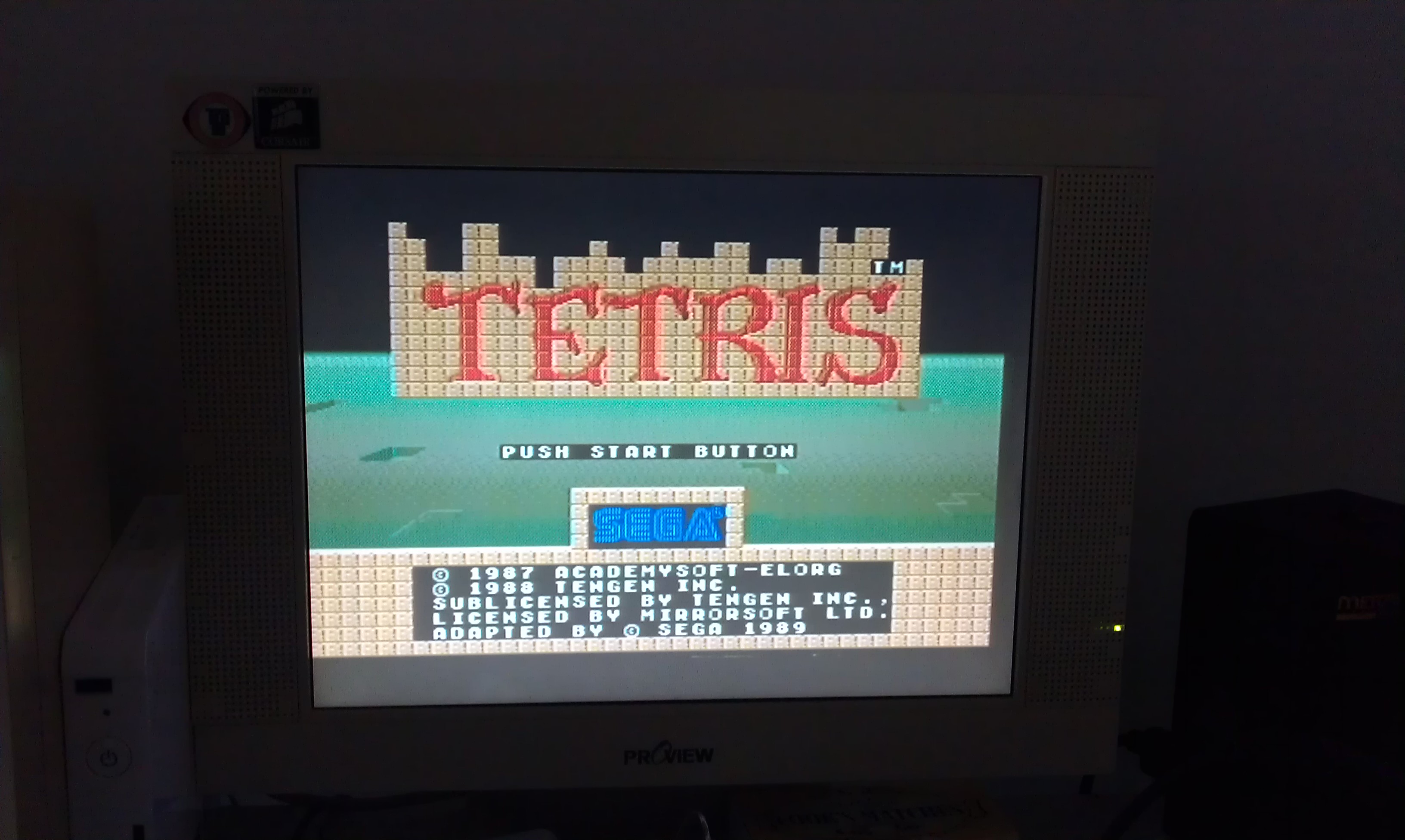
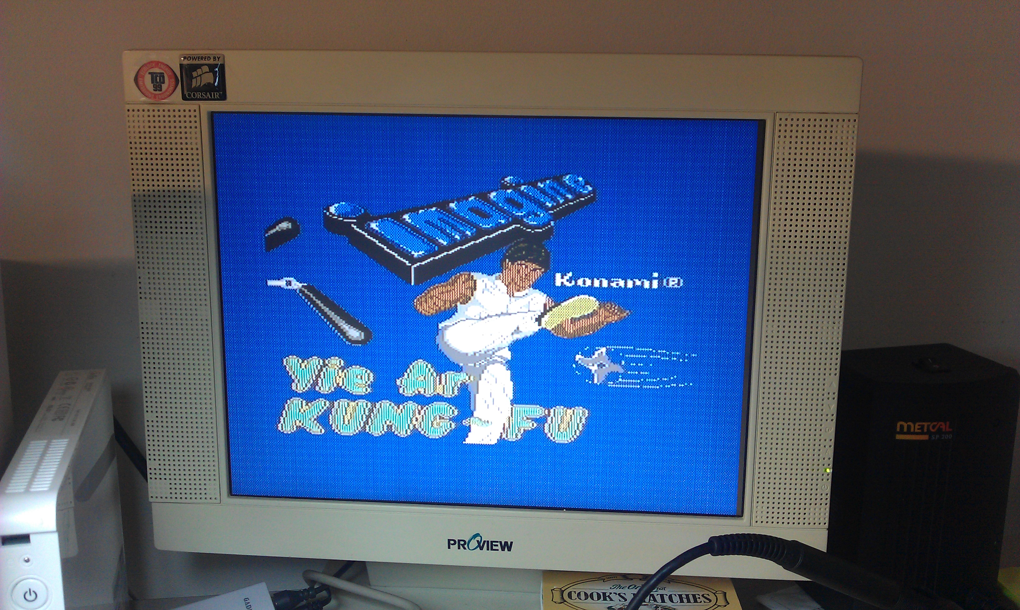
Apple IIe enhanced ( Platinum ) – NTSC 50hz to 60hz conversion

 Computer Repair Logs, Mods, Repair Logs  Comments Off on Apple IIe enhanced ( Platinum ) – NTSC 50hz to 60hz conversion
Aug 252019
 

The final revision of the exported Apple IIe and Platinums use the International NTSC PCB, this ships with a very odd 50 hz NTSC configuration. The stock motherboard is fitted with a 14.238Mhz and requires the original 50hz Apple IIe Color Monitor to display a non monochrome picture on the screen. A standard 60hz capable NTSC monitor or 50hz PAL monitor ( as expected ) fails to pickup the colour on these machines due to some odd Hybrid combination.

Unfortunately my Apple Color monitor has a dead flyback and all efforts to source a replacement or substitute part went nowhere so I had to find an alternative. One alternative is using a PAL / Color encoder card but these are rare and expensive whenever they turn up.

The theory to get colour involves changing the crystal at Y1 from 14.238Mhz to 14.31818MHz, this is logical and seems to work for most people who have tried this modification. One of the issues surrounding the crystal has already been discussed at length on the various forums, it must have an ESR of 25 ohms and not any off the shelf crystal will do apparently. Most people have had success using the specific type of crystal with the right characteristics, unfortunately I have not. After changing the crystal at Y1, I still had a black and white display on all my monitors ( Sony PVM, Philips & TEAC LCD  ) which are capable of displaying 60hz NTSC in colour.

The PVM and my Commodore 1084s PAL monitor ( Philips made ) had no issues with locking on to sync despite the black and white monochrome picture ( expected in the 1084s case ). My Philips LCD still interpreted the signal as PAL even after changing the main crystal. In fact the signal was not stable and both LCDs were struggling to lock on to sync permanently, with the picture slightly shimmering or going completely out of sync for at least half a second ( as in the TEAC’s case ).
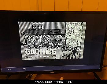
 

This has left me scratching my head as it appears that ALL my monitors were very picky , yet other people had success.

The Technical Reference Manual, in chapter 7 states that the IOU ( input / output unit ) handles and generates the video signals, video blanking, horizontal  signals via some internal counters.

http://www.applelogic.org/files/AIIETECHREF3.pdf

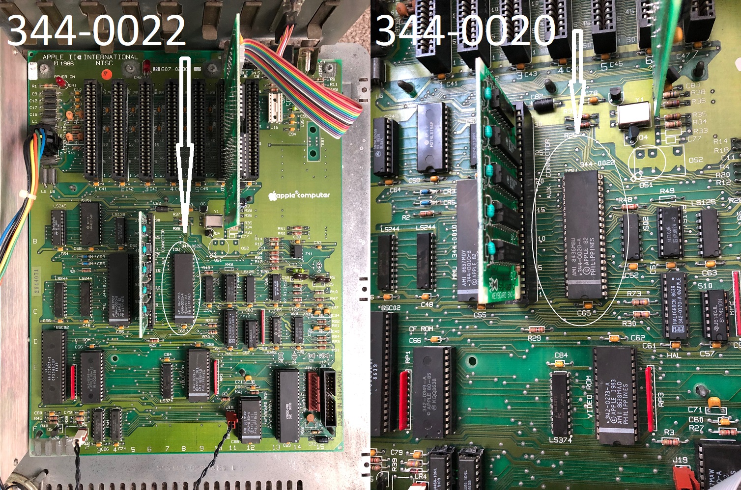
There are several different versions of the IOU but information out there is rather confusing and in some cases incorrect and that’s something I’d rather not cover at all. The NTSC International and even the PAL models use a very specific version of the IOU not found in the non export, U.S versions.

  • IOU 344-0022 ( used in International NTSC 50hz and PAL models ).
  • IOU 344-0020 ( NTSC 60hz ).

I had an idea to swap out the original 344-022 IOU for the 344-0020 and I took my chance on a non tested earlier IIe PCB.  Thankfully only 4 RAM chips were bad ( mostly Micron, surprise surprise! ) which I’ll cover in my next repair log. I very carefully remove the original IOU, installed a machined pin socket and swapped the IOUs over. The original IOU still works in the other IIe after all that surgery ( Phew! ).

At some point later on I had to replace the RAM as well most likely caused by accidentally handling static prone devices without an anti-static wrist strap ( whoops! ). Not to worry, I have plenty of spares.
 

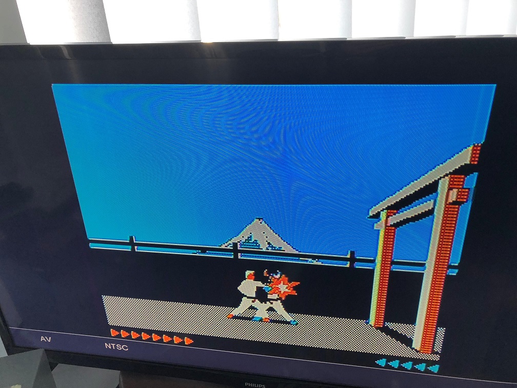
The results with splendid colour on my PVM!


And a valid NTSC signal on my Philips LCD ( Karateka in action! )
 

Conclusions: It was suggested the possibility that the original IOU was damaged or partially faulty ( I have to keep that in mind ) but I’ll never know unless someone else confirms the same or I can get my hands on another IOU ( 344-0022 ). I previously had the same exact issue in another IIe before I sold it, however I was using FOX143-20 branded crystals ( which have an ESR of 40 ohms ) at the time rather than the proven to work ones below which have an ESR of 25 ohms.  I still have my FOX crystals on hand, so at some point I’d like explore those again and see if colour is still possible given I’ve swapped the IOU over to the 60hz version.


The following crystals have been proven to work.  Still no colour on your International NTSC board  ? Try a different IOU by substitution.
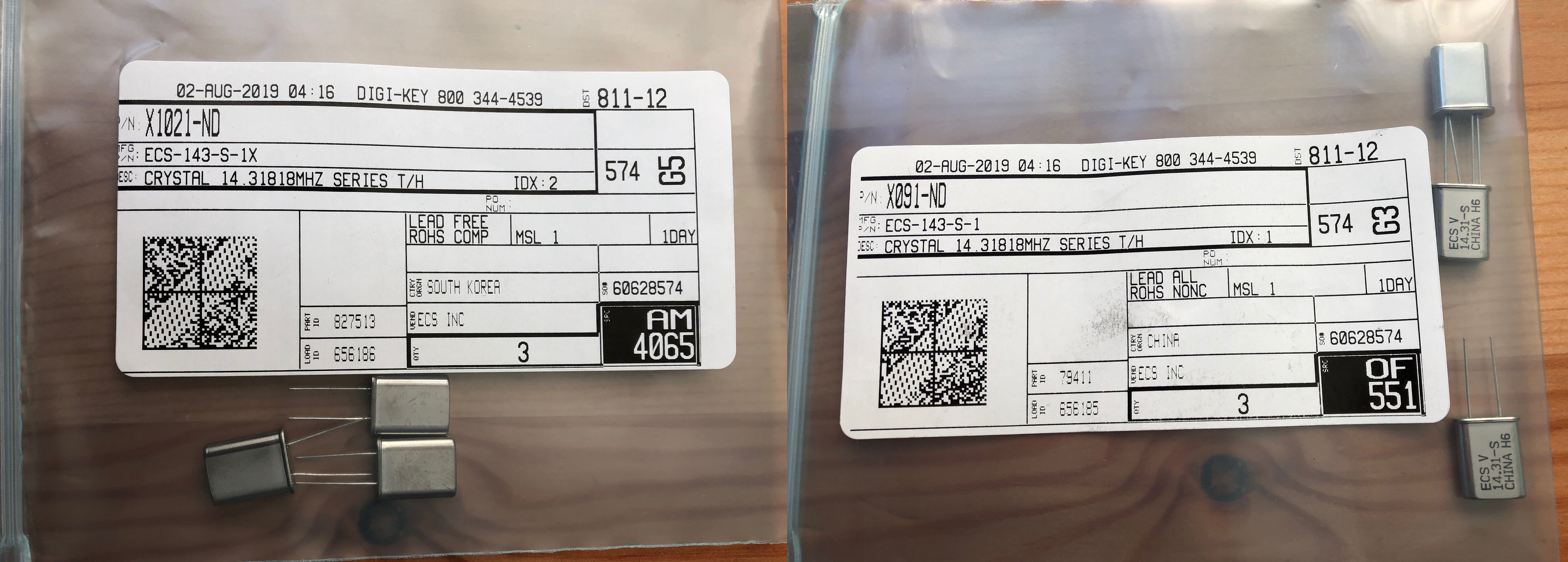
ECS-143-S-1

ECS-143-S-1X.

These can be found at the link below.

https://www.digikey.com/products/en?keywords=ECS-143-S-1

Mar 292016
 

Sometimes it is very annoying when you have placed your arcade monitor vertically and certain games are shown upside down and  even worse they have no option to flip the screen.

It happens very often with older games but sometimes even with newer games from the 90s.

In these cases you have 2 options: reverse phisically your monitor or reverse the yoke  on the pcb of the monitor (not very safe).

Now I show you a new option available only when the games were also prepared for cocktail tables (that means they have already the circuit to flip the screen for the second player)

In this first “flip screen” hack I will take Zaxxon / Future Spy hardware as an example


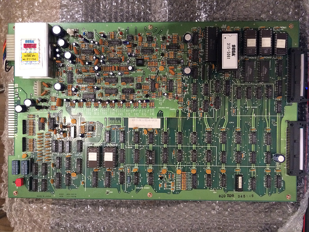
Future Spy_2

These games have no flip screen option but they have the preparation for cocktail tables play.

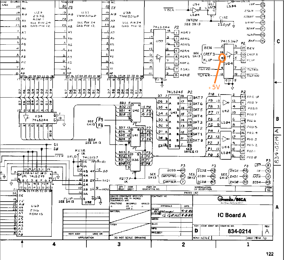
The board is very big but luckily schematics are available and they are very clear to understand.

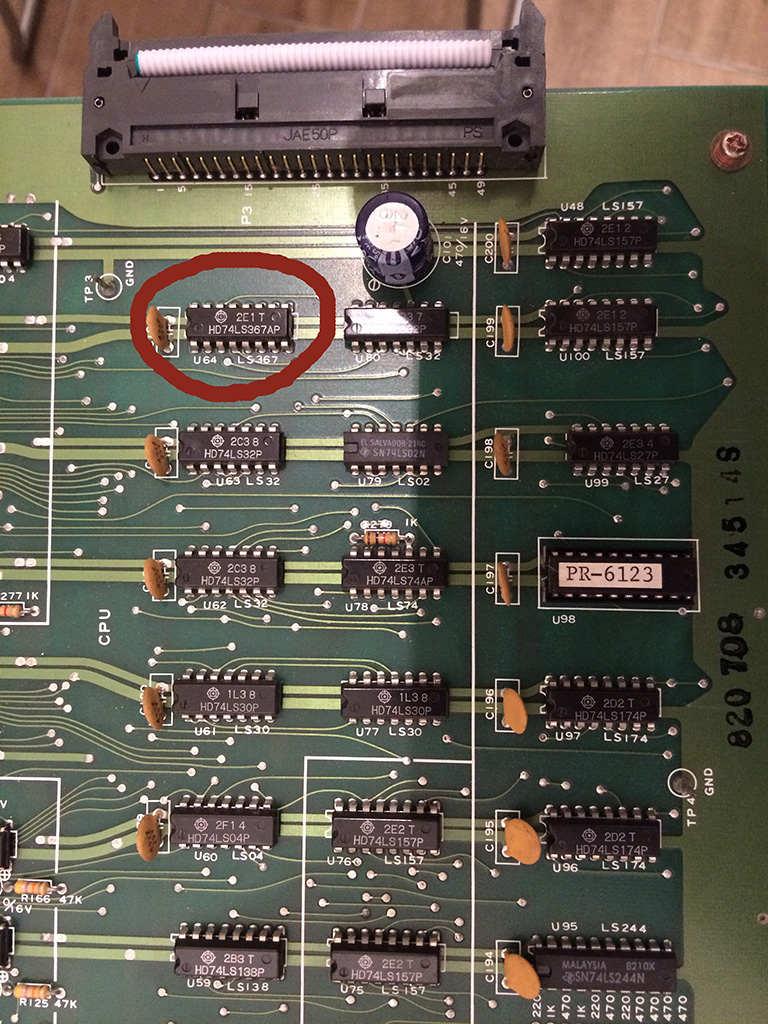
The hack is very simple: input nr.4 of 74ls367@U64  is normally LOW for first player game and HI for second player game.

We have only to force pin 4 to HI (+5V) using a wire so that the screen is always flipped as it was playing the second player even in upright mode.

Zaxxo_flip screen hack


FS


Very simple and effective!

Sep 232012
 

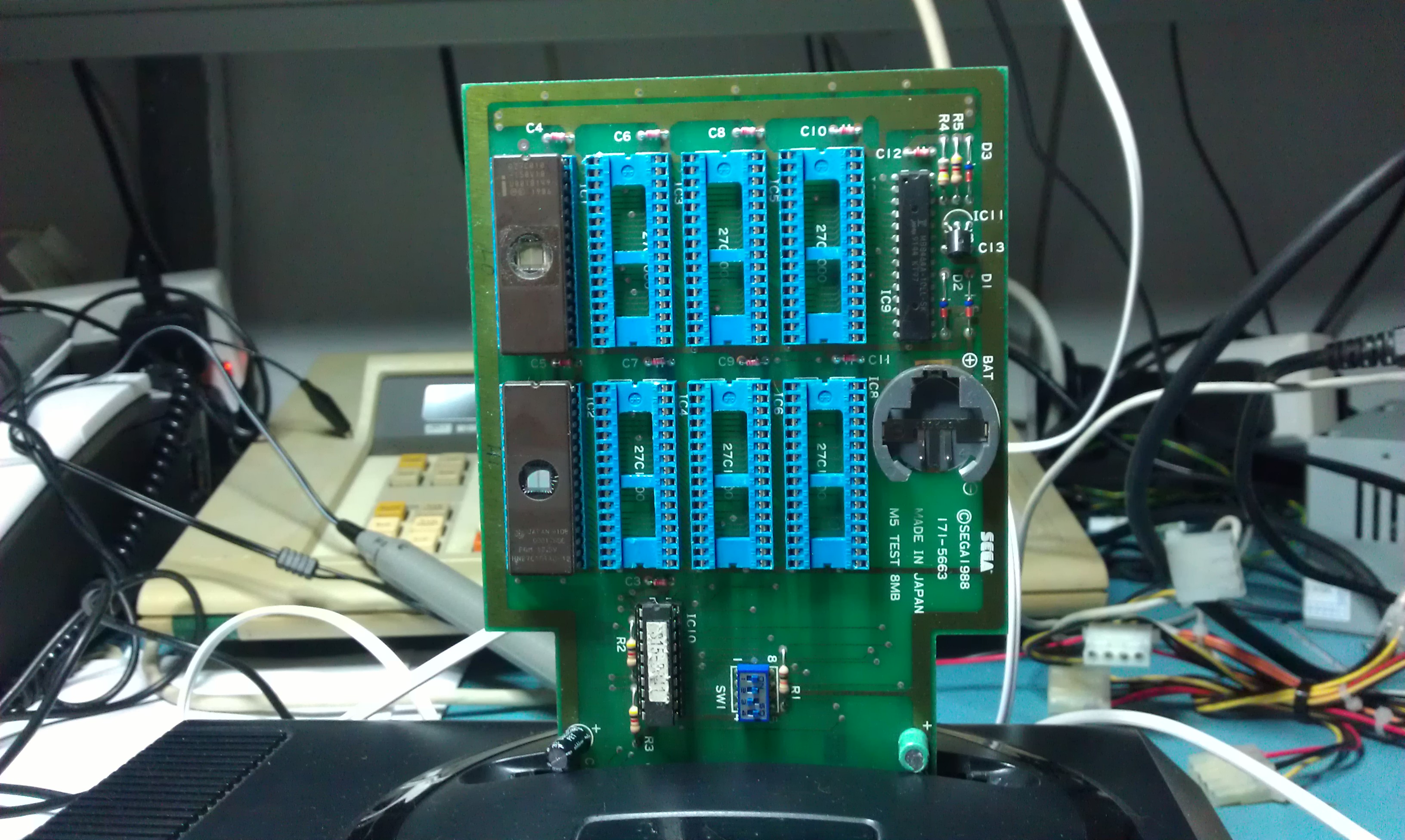
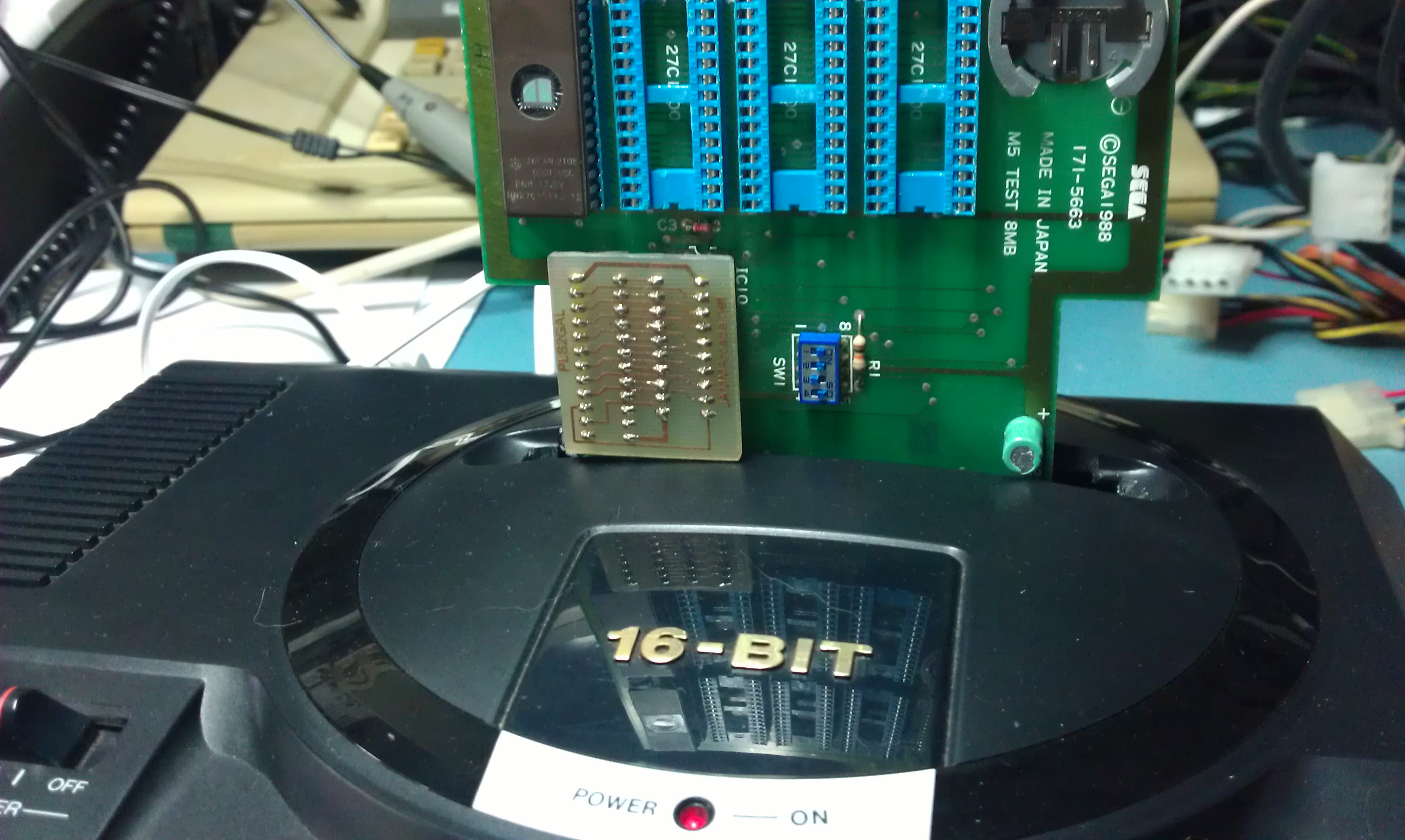
Today I started playing around with this EPROM PCB I recently got.
Before I do anything I needed to change a decoupling capacitor that has had its legs almost completely pulled out of the body.

The silkscreen says the EPROM’s should be 27C1000’s. I used 27C010’s as they are the same pinout.
27C1000 chips are 8 bit so the data must be split across 2 EPROM’s.
I looked for a rom 256KB in size and deinterleaved it into HI and LO files. Then burnt them onto the EPROM’s.
After taking a 50/50 chance on which way round these EPROM’s went (and getting it wrong) I found that the LO side goes on the bottom row of sockets and the HI on the upper rom.

I fired the thing up and…..

SWEET!

Now was also a good opportunity to test out my conversion of that old CK2605 PLA into a GAL22V10.

All good here too.
Quite satisfied with that. If only the new Angry Birds conversion would fit onto it.
Still have to do some testing and see what those DIP switches are used for

 Posted by at 12:10 pm
Sep 092012
 

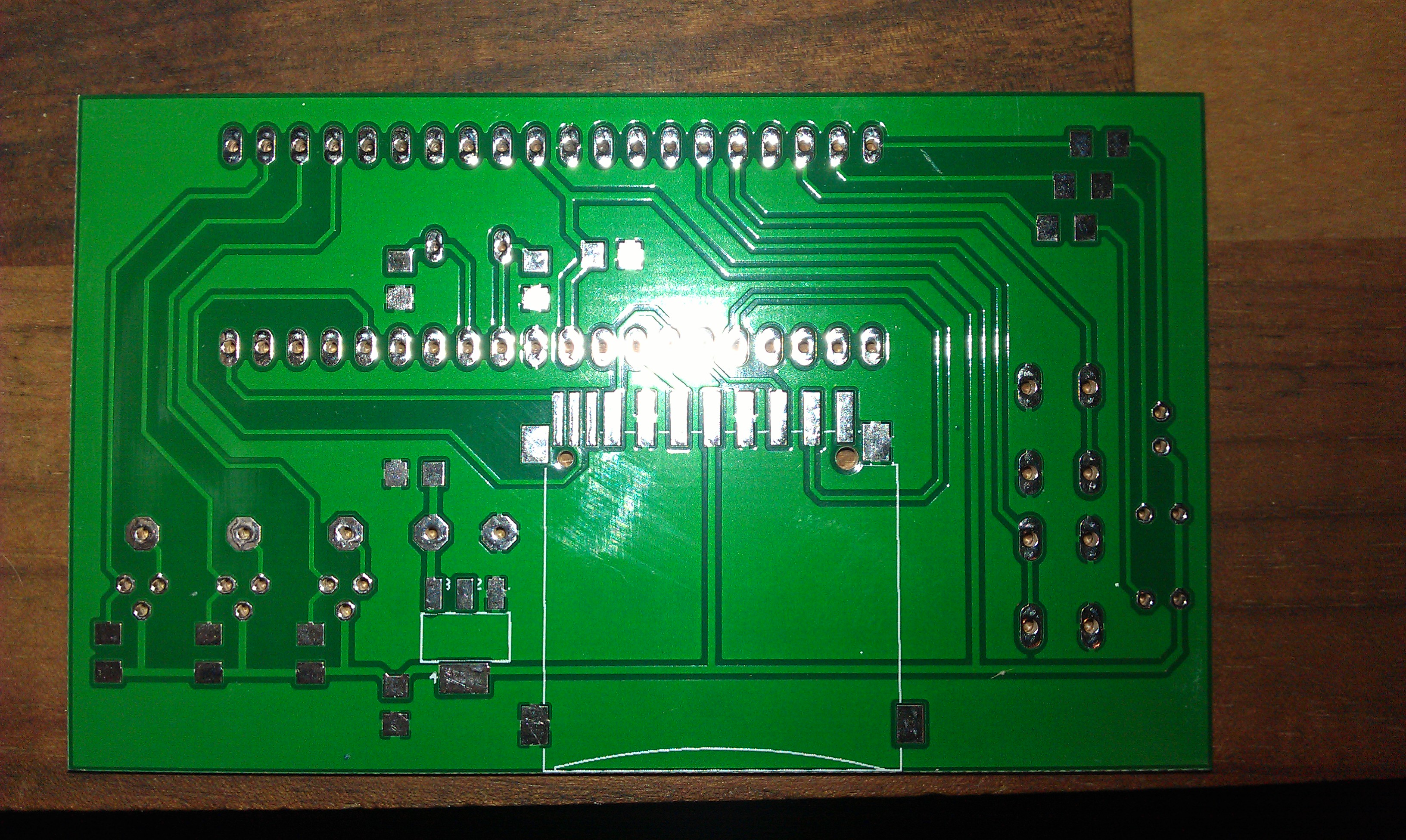
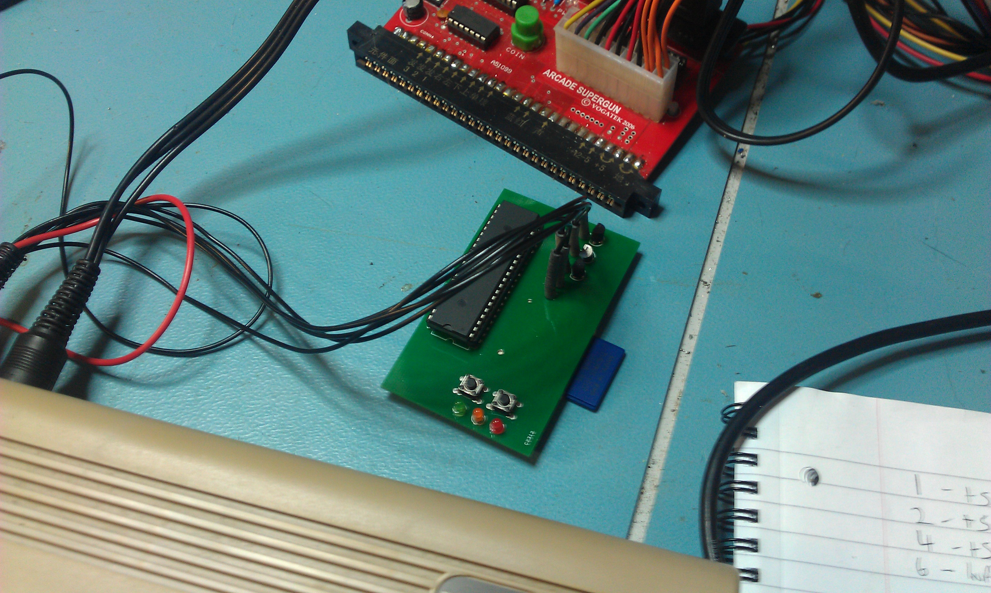
Quite a long time ago I had some more SD2IEC boards made up for the C64.

I hadnt really done anything with them and I had promised id make one up for Stiggy.
Today I finally got around to making one up and im pleased to say it seems to work.
The wires need tidied up a bit but it loaded up a game no problem.

And that was the last of my outstanding projects.

 Posted by at 12:29 pm

Progear “decrypted bootleg” fix

 Mods  Comments Off on Progear “decrypted bootleg” fix
Jul 252012
 

There was a forum post on the J+ forums today asking why his Progear fails the ROM checks in the test menu.
This reminded me that I had made a little fix for this a while ago so thought Id write it up.
NOTE: No modified ROM’s will be available for download on my site but instructions to help DIY are here

The ROM tests fail on this version of the game because it looks like this version was once the Phoenix edition but has been hacked a little to remove the Phoenix screen at boot up. Since Razoola already fixed the checksum value in his releases, the modification changed the end result slightly which make the test fail.

So, basically I started off looking at disassembly of the code.
The code that checks the ROM’s is at location $395c

The checksum loads the first HEX value into a register then sequentially adds the rest of the HEX values into it. The final result will be the ROM checksum.

It looks like Razoola also modified the code to incorporate a more thorough test routine. The original started its checksum after the point where the expected checksum value is stored where as Raz’s code checks the whole thing.

This left me with a couple of ways to modify the code. I could either revert back to starting the checks after the stored value or I could add some filler values in an unused section of ROM in order to modify the final value.
I chose the first method for no particular reason.

The start address of the checksum is defined at address $3962 and original reads LEA ($1, A0), A0
This loads address $1 into register A0 as the starting address.
I changed this to read LEA $FFF, A0

Now the game will pass its tests on ROM 0. The same process was used to fix the ROM 1 issue too.

 Posted by at 7:16 pm