Spectrum +2a composite mod

 Mods  Comments Off on Spectrum +2a composite mod
Jul 152012
 

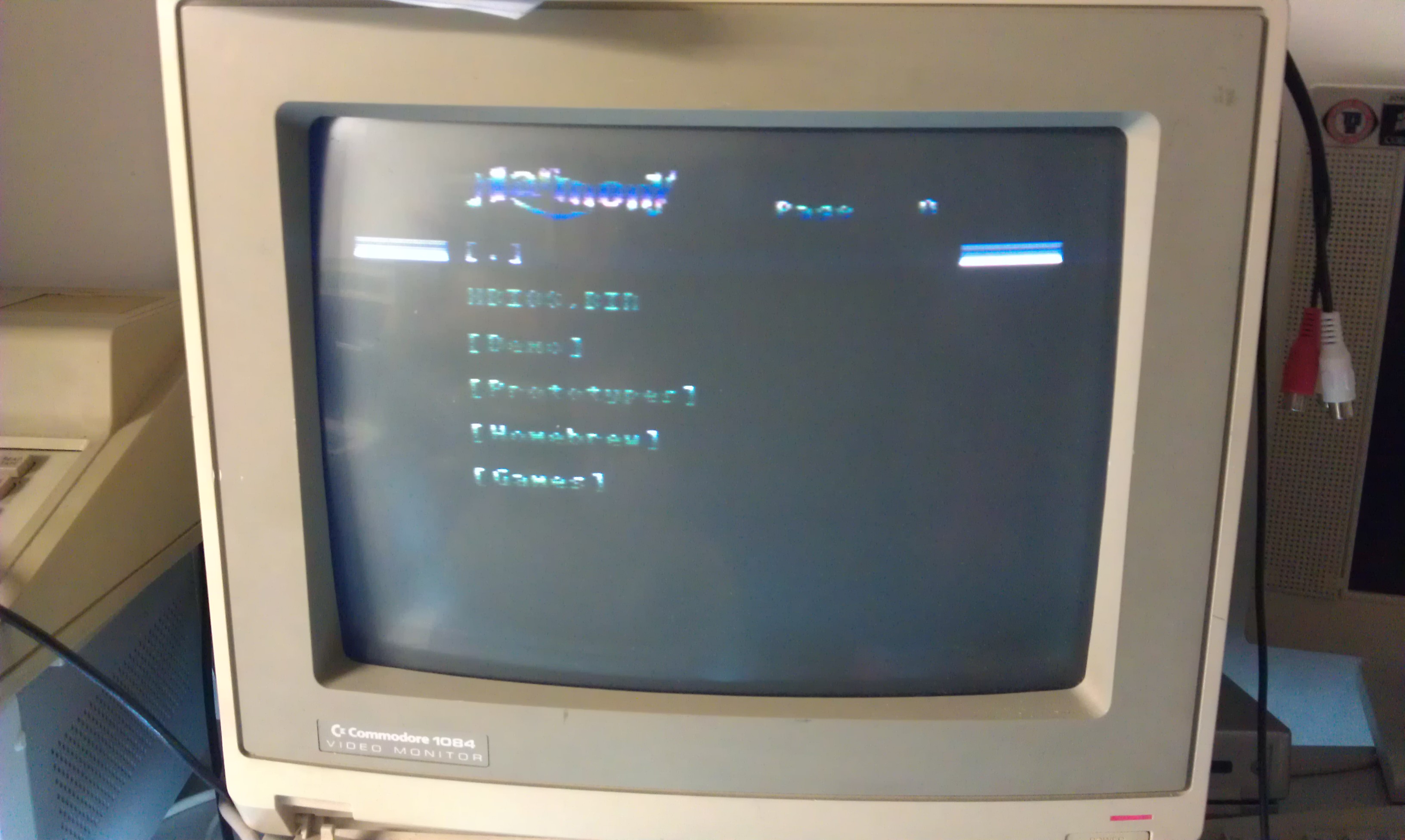
Having recently obtained my +2a and suffering the poor quality that RF gives, coupled with the pleas of my good friend Mr Stiggy to somehow get a composite output I set about making this simple yet extremely effective circuit.
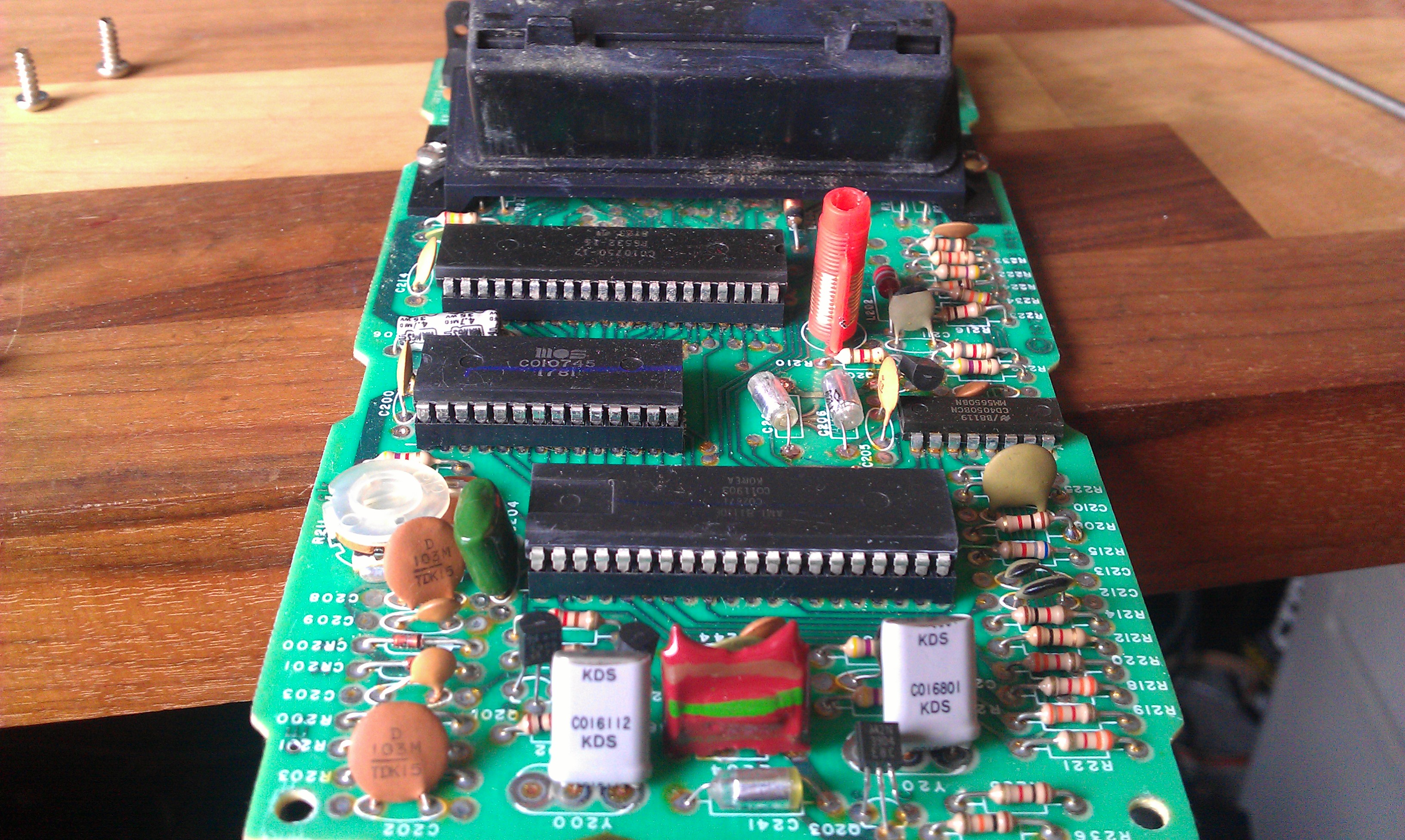
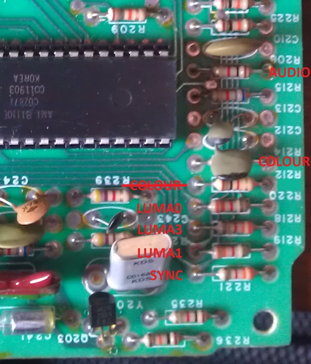
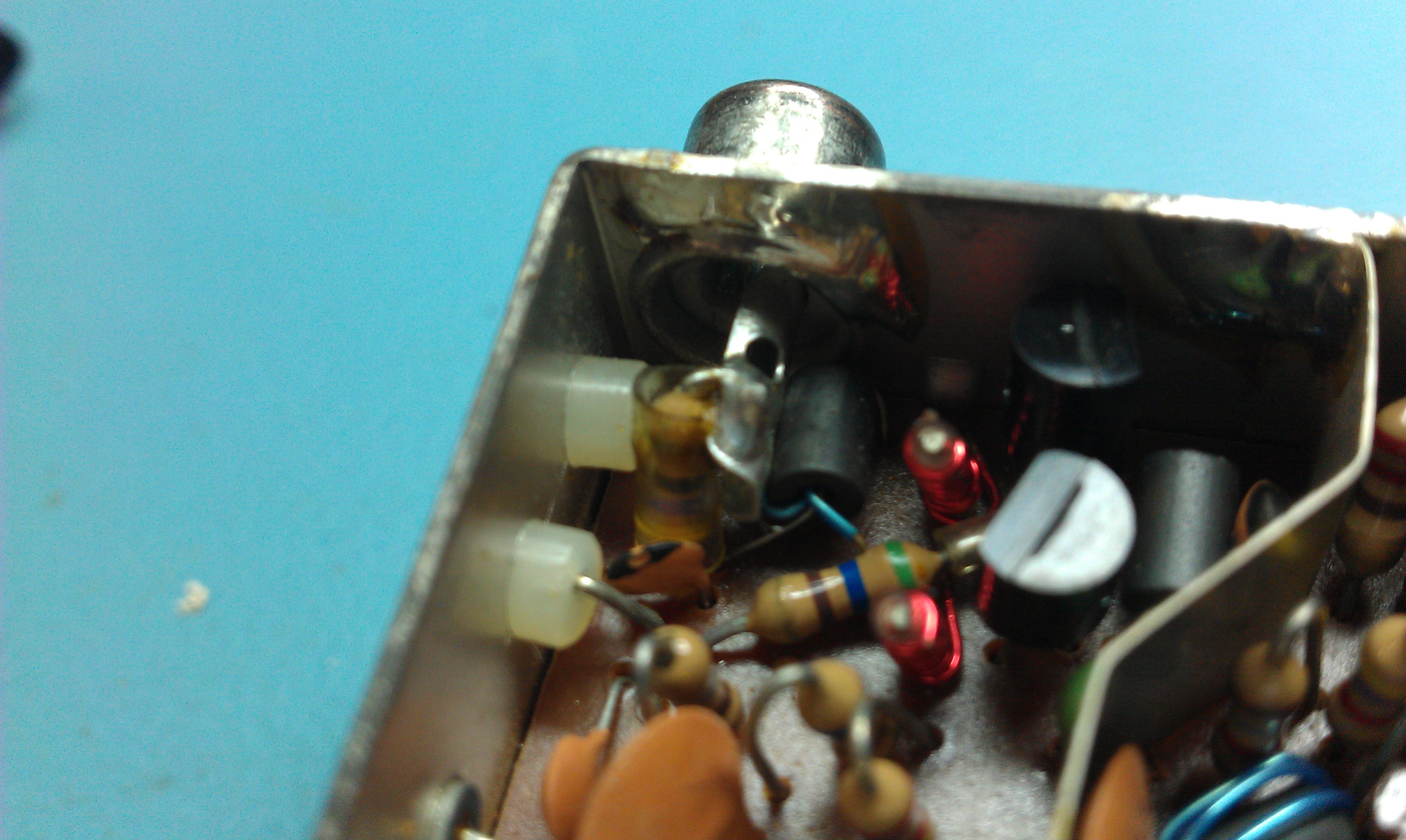
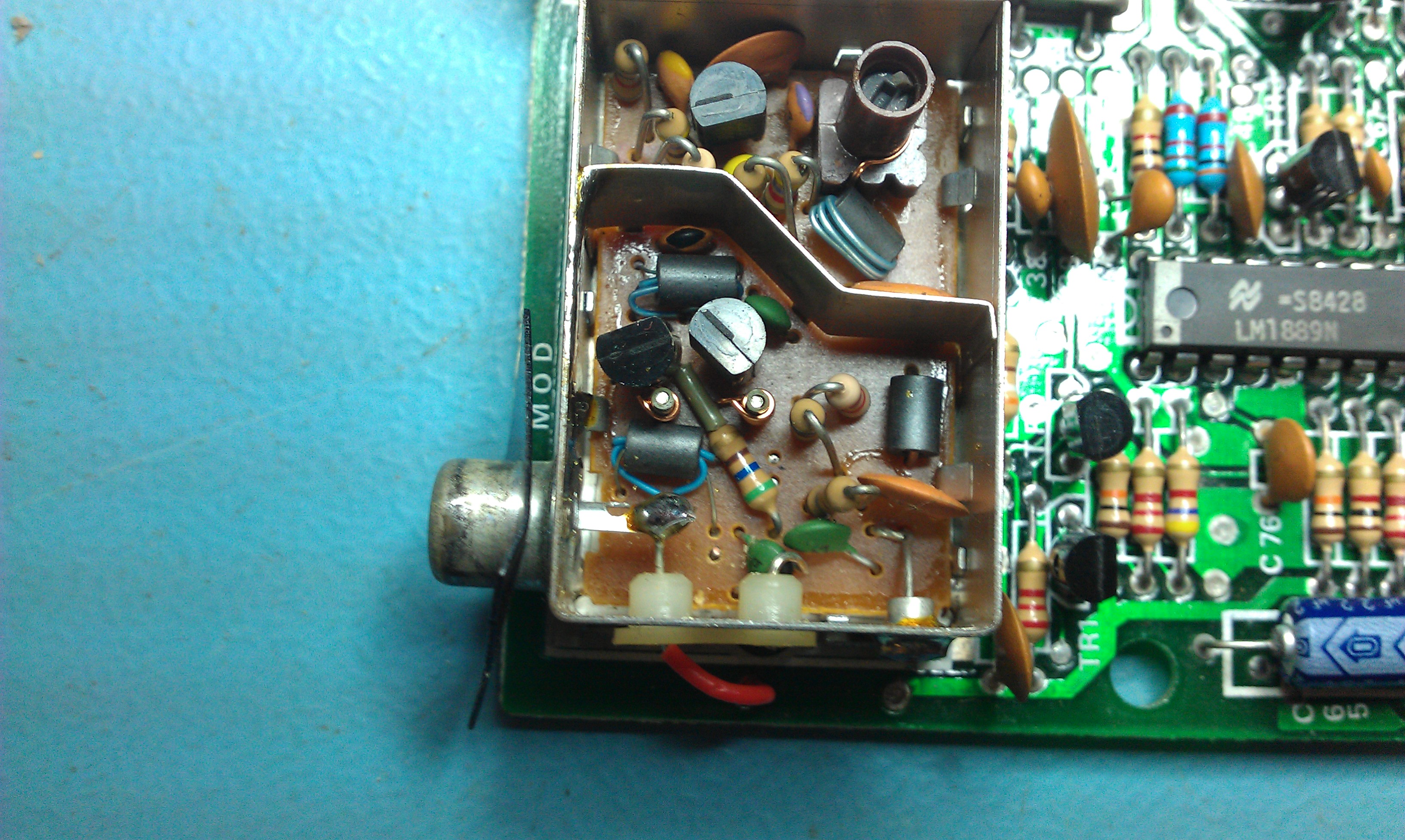
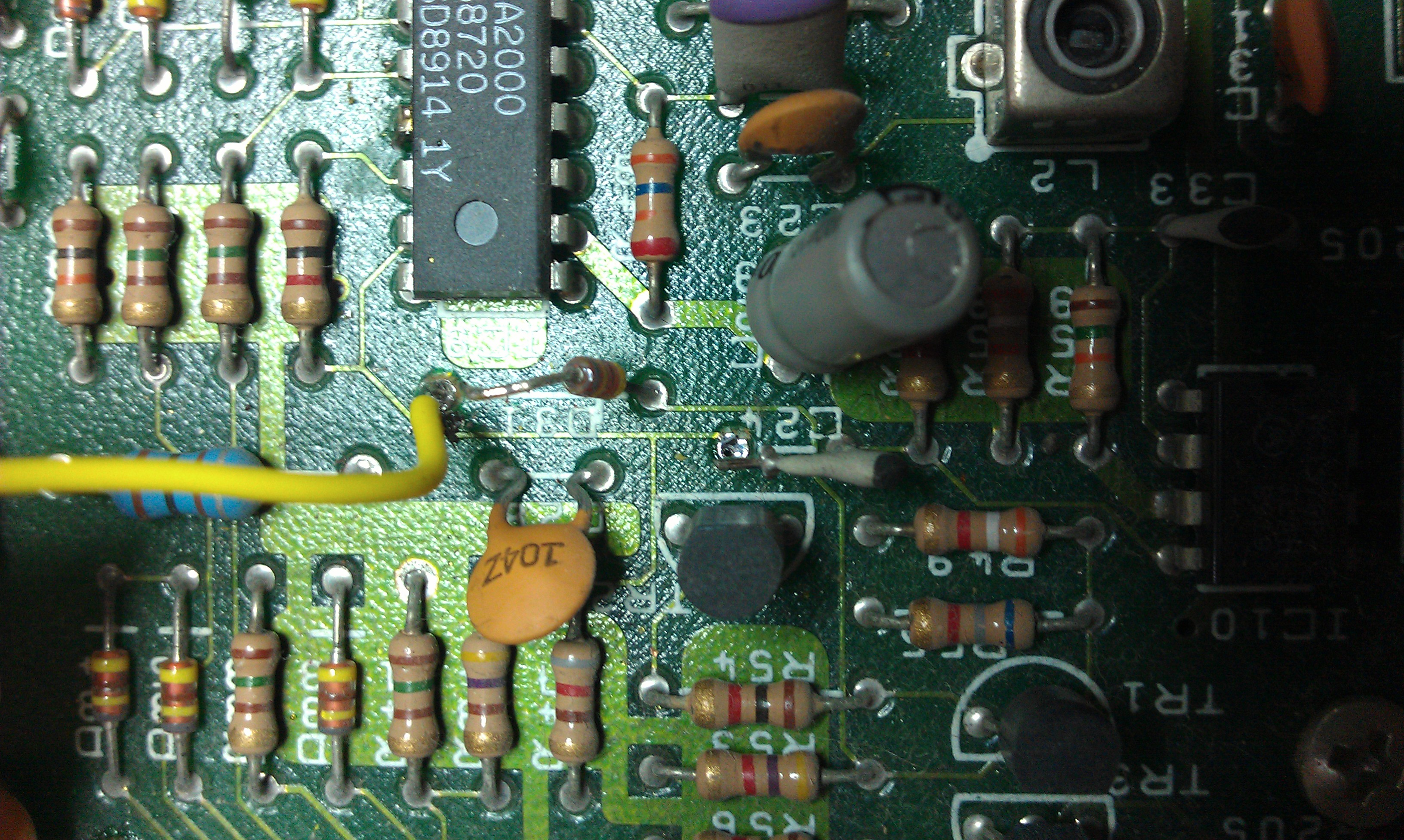
The TEA2000 chip actually gives a composite output on pin 6 which is nice. I also think that this signal goes right into the RF modulator but I couldn’t get any picture to appear from that so this circuit is no more than a small amplifier of that composite signal.

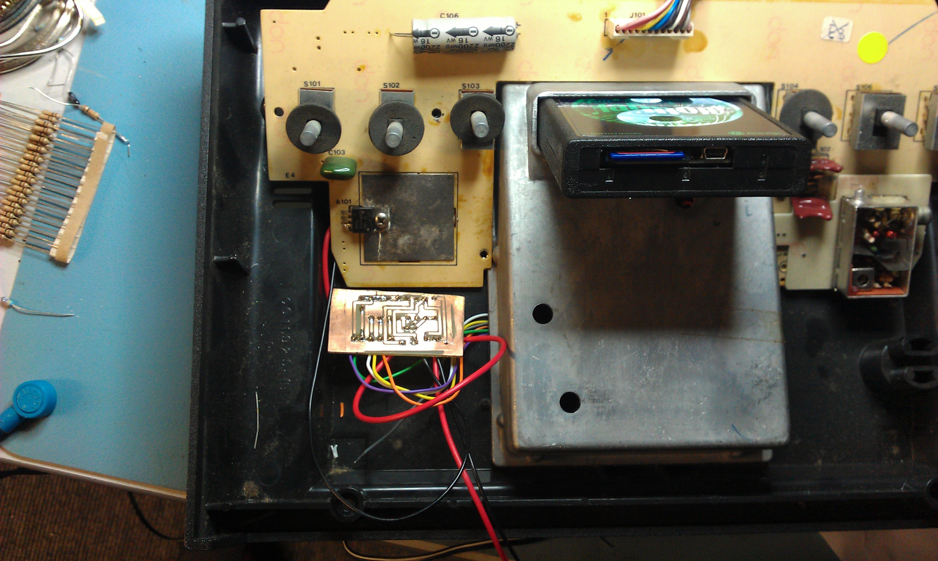
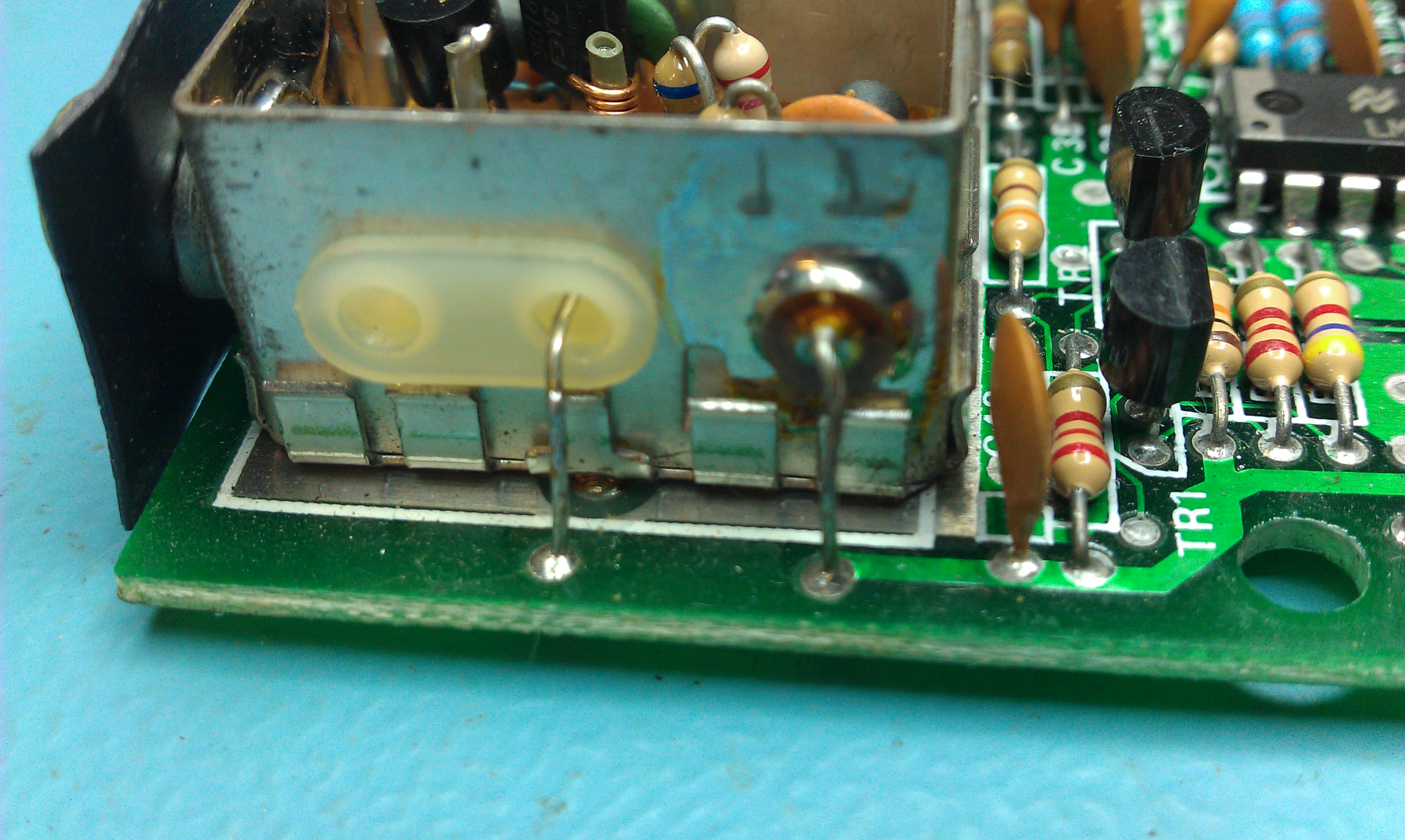
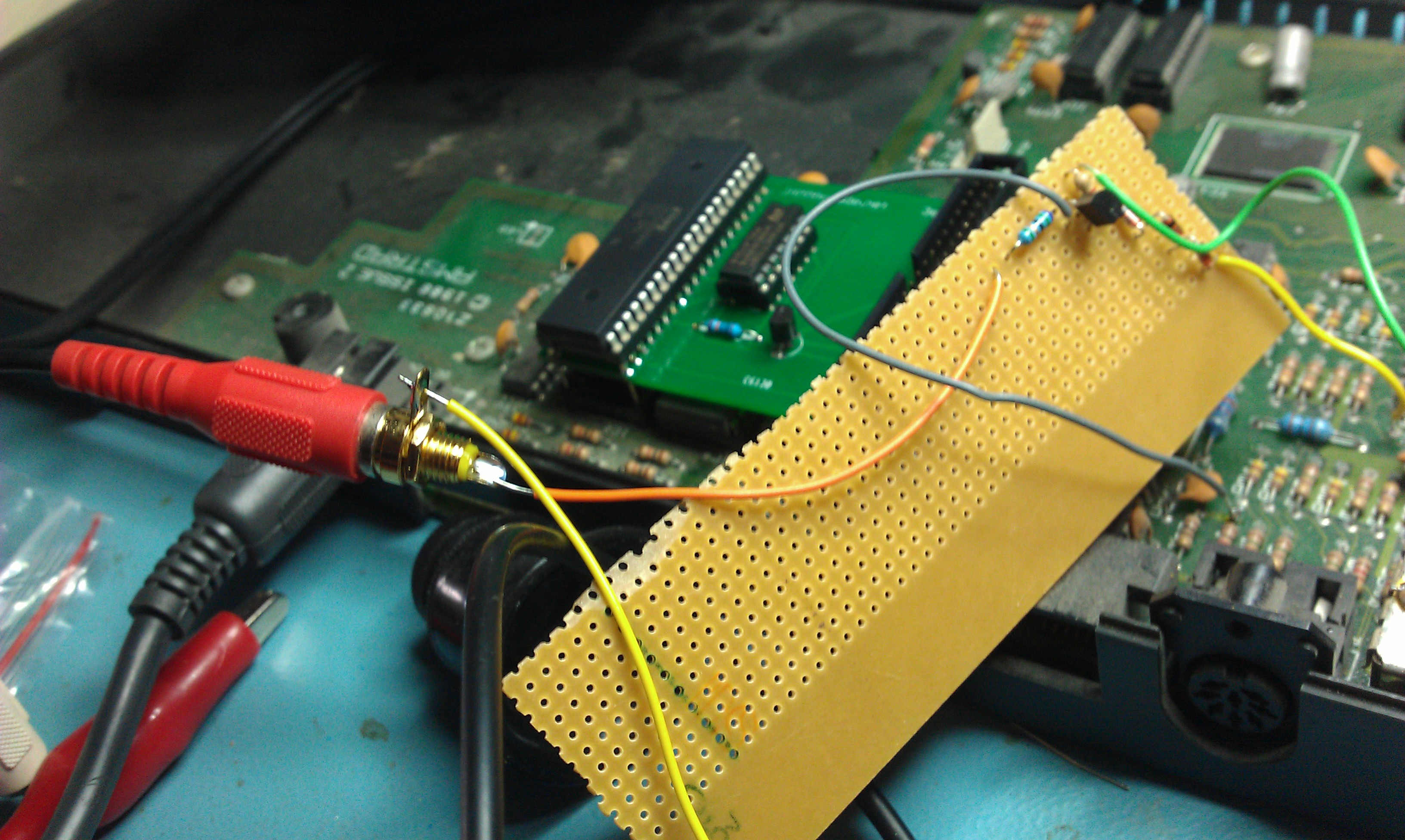
My veroboard design is sloppy and rough with no coordination of wire colours what so ever but it works very well and im happy with it for now.

The audio present on the same signal line causes quite a bit of distortion in the picture. To remove that just remove capacitor C24.

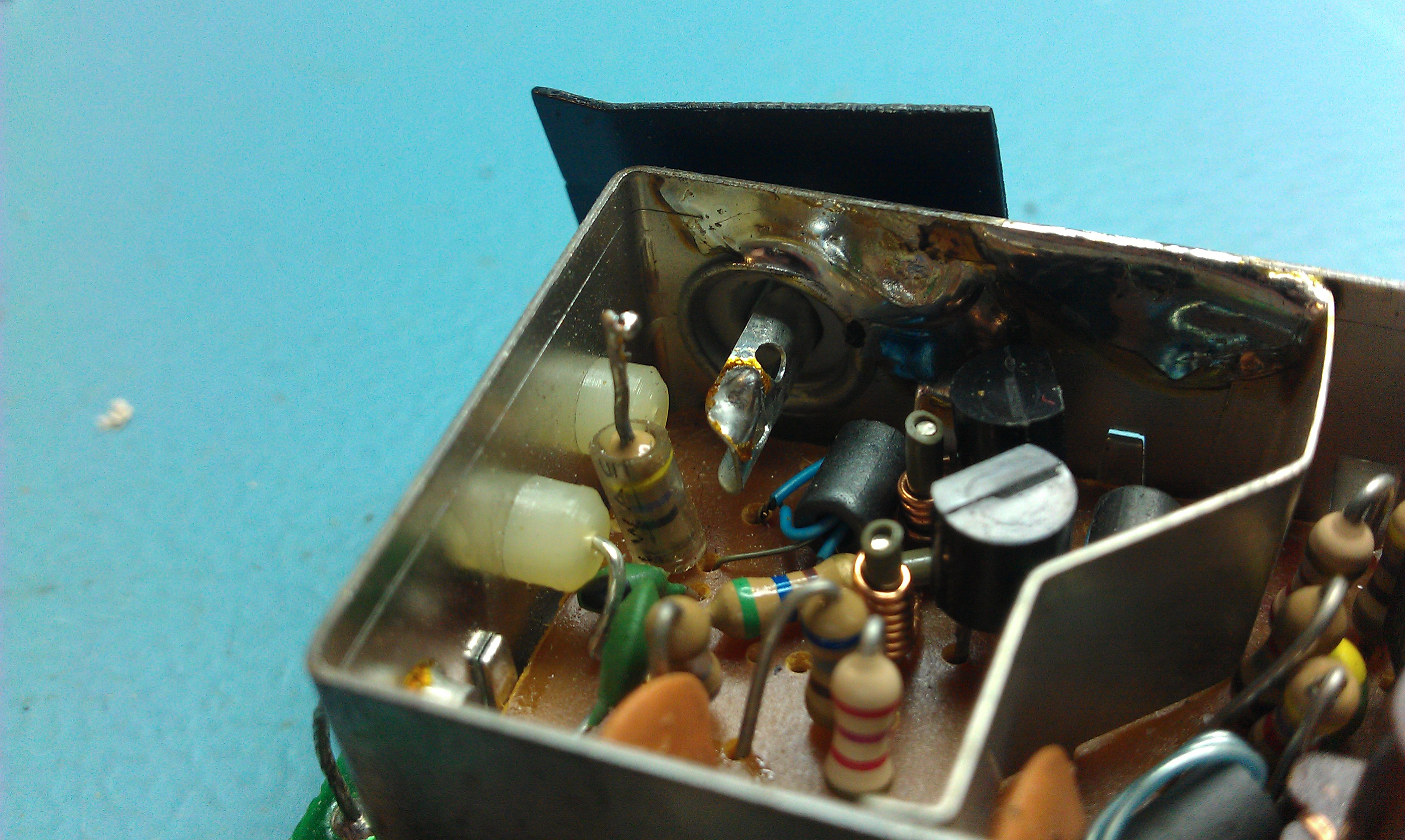
I then went on to cut the board down and also removed the RF modulator altogether to end up with this

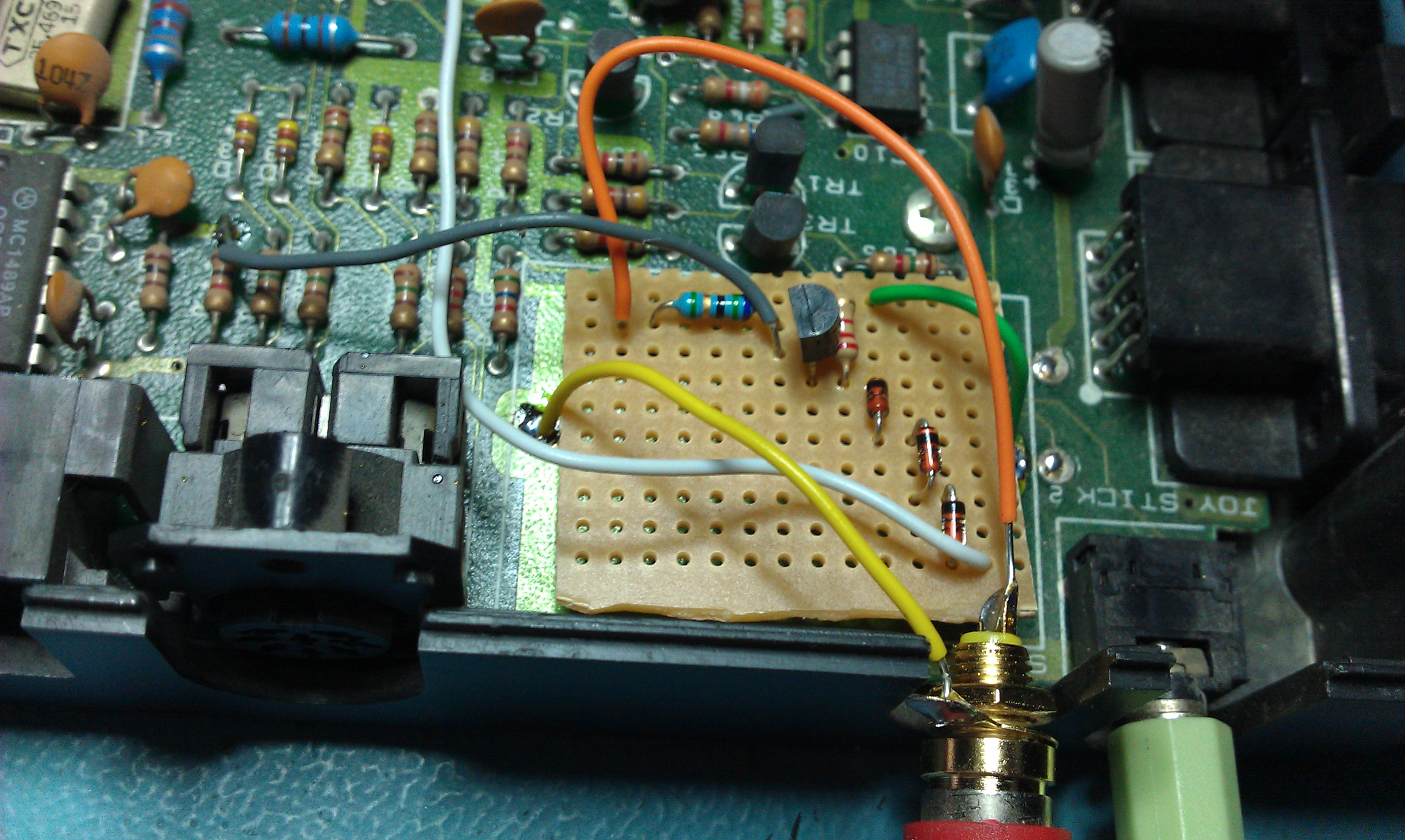
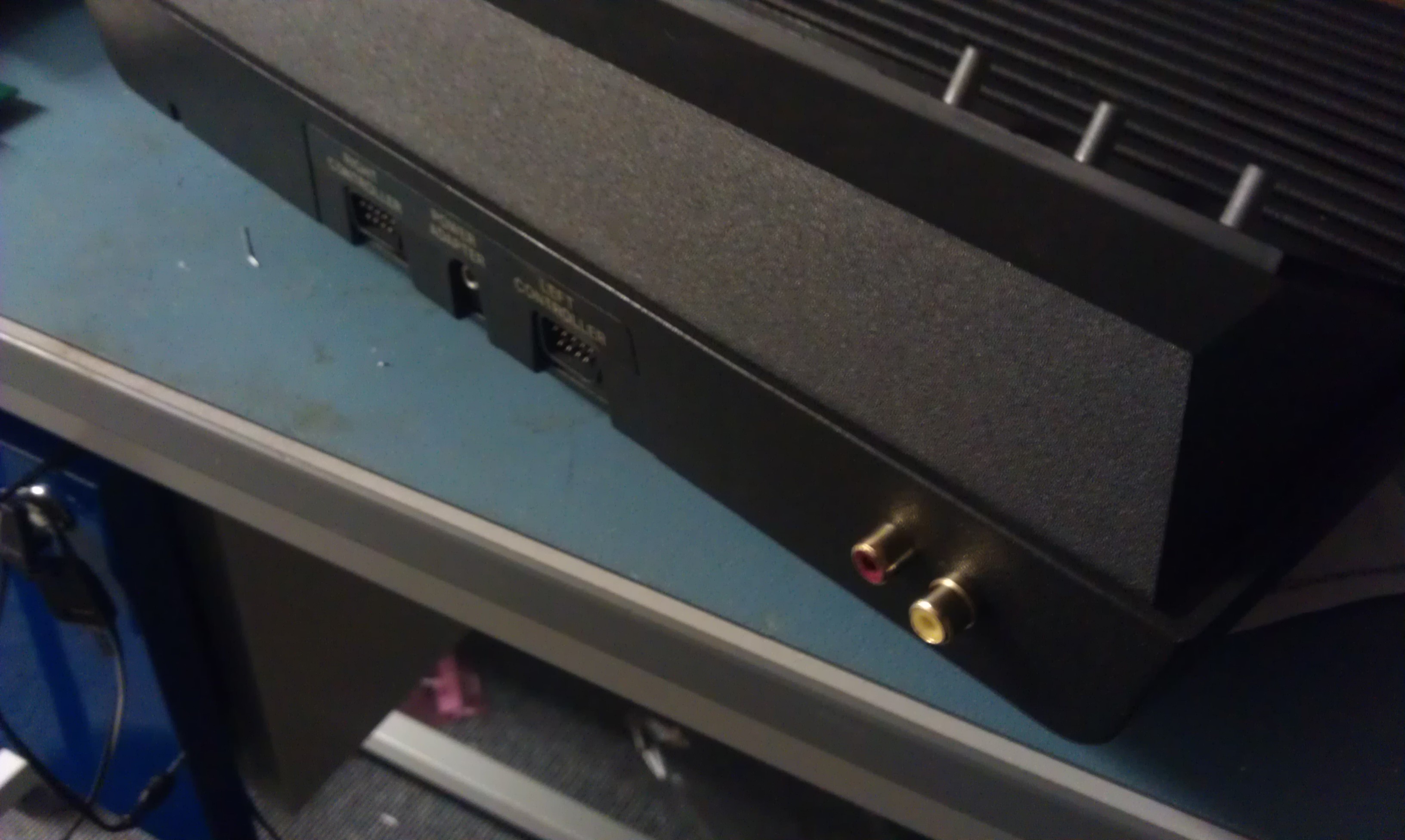
Im going to order a PCB mounted socket and fix the board in place somehow and this will be fully usable. Audio output is now provided by the audio jack to the right next to where the old RF output was.

 Posted by at 12:09 pm
Jun 212012
 

Looking at various methods of adding IDE capability to a Spectrum I came across the “simple 8 bit” interface.
I had a couple of board made up cheap and here it is in all its simple glory


The card sits in the Z80 socket and the Z80 CPU sits in a socket on the PCB, all very simple.
Its only 8 bit and has its limitations but I look forward to experimenting with it

Works very well for my very limited testing but I’m not at all familiar with Spectrum’s so will probably take a little while before I can transfer anything “commercial” over the the CF card.
If anyone know a nice easy way to transfer images on the the CF card for use with the +3e ROM’s then please let me know

 Posted by at 5:41 pm
May 262012
 

Ive been wanting to get a RAM upgrade for my VIC20 ever since I found Robotic Liberation demo wouldn’t load from SD2IEC unless it was expanded. As eBay prices have gone stupid I opted for the homebrew piggyback method.
This method involves soldering a couple of 6264 RAM chips onto the Kernel and the BASIC ROM’s and lifting a few legs to run some wires elsewhere.
The guide I followed can be found here so I wont bother rewriting it.
Its pretty easy to follow but found it best to read through it a few times before starting.

I had already replaced the Kernel ROM in my VIC for a JiffyDOS one using one of my adapters so some of the work was already done for me regarding the pinout differences but as the guide says, best to check the operation after each RAM is fitted to confirm its working.

Anyway, here are a few pictures


You can see my custom board in the lower right hand corner of the PCB


And following the upgrade


Completed mod


And finally, Robotic Liberation

Its pretty easy to do and fairly quick once you understand the instructions.

 Posted by at 5:48 pm
Mar 132012
 

Stiggy gave me an Atari 2600 he had going spare when he came round.
Ive never owned one before but its always been on my list.

The old 2600 only has RF out which is completely rubbish on modern TV’s so it was off to the internet to see what kind of mods exist.
After a short while of checking different sites I came to the conclusion that there is no decent, definative guide for my version of 2600.
My mainboard seemed to be a little different in layout than what the guides were based on.

Looking at the other guides they show that the video signals all come from one IC which is standard across all the 2600 models so I traced out the SYNC, LUMA0, LUMA1, LUMA2 and COLOUR signals myself and ran some wires from the points and to the outside world.

As you will see, there is a “COLOUR” label with thats crossed out. This is because I originally followed the circuit through the resistor where I should have followed it from the resistor up to and through the capacitor above it. I ended up tapping into a +5v line by making this mistake so ended up with no signal at all.

I made a quick design in EagleCAD and etched a board based on a simple transistor based amplifier running the LUMA signals through various size resistors.
After taking my +5v from the nearby voltage regulator, fixing my mistake that I highlighted earlier and doing a test with a loaned Harmony cartridge I saw a fairly decent image on screen. Its a little dark and this can probably be changed with fine tuning some resistor values but this will be more than acceptable for me.


The pictures don’t look too impressive on the photos but they are a joy compared to RF.
Ive yet to hook the sound up but the wire is there for it, this will be tomorrows job along with properly fitting the phono plugs.

EDIT: Sound is now hooked up and fully working. All phono sockets are fitted. What a nice mod it was.

 Posted by at 8:27 pm

ZX Spectrum composite video mod

 Guides, Mods  Comments Off on ZX Spectrum composite video mod
Oct 152011
 

There is a very simple mod that you can do to bypass the RF modulator and use the same connector for a composite output.
It takes a few minutes to do this and works really well.

First job, remove the lid on the RF modulator.

There is a resistor connected to the centre pin of the RF output socket, remove this and bend it up out of the way.

On the outside of the RF module there are 2 wires leading from the modulator to the PCB. These are the VIDEO IN on the left and +5v on the right.

Remove both of these from the PCB.

There is a second insulated hole in the the side of the modulator unit that is unused. Get some wire and strip enough insulation off the end so you can feed it through and then solder it onto the centre pin that the resistor was originally connected to.

As im never going to be using the RF again I went ahead and totally removed the old VIDEO IN and +5v wires. I also removed the old resistor. This step isnt necessary but if you leave them in make sure they are insulated so they can short against anything.

Fire it up and check out the Spectrumy goodness.

 Posted by at 1:15 pm