Jan 182015
 

There are not only arcade boards to repair in the life…but also computers (and japanese ones are really cool)!

I got from Japan this ‘junk’ NEC PC-9821AP2/U8W in the mail some days ago (after a wait of two months), seller said only it was not working without going into details.

PC-9821AP2-U8W

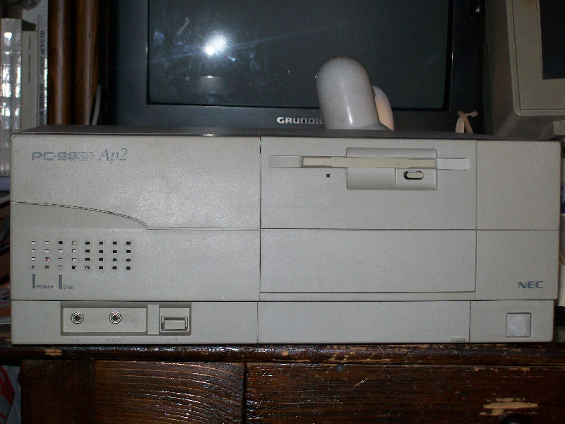
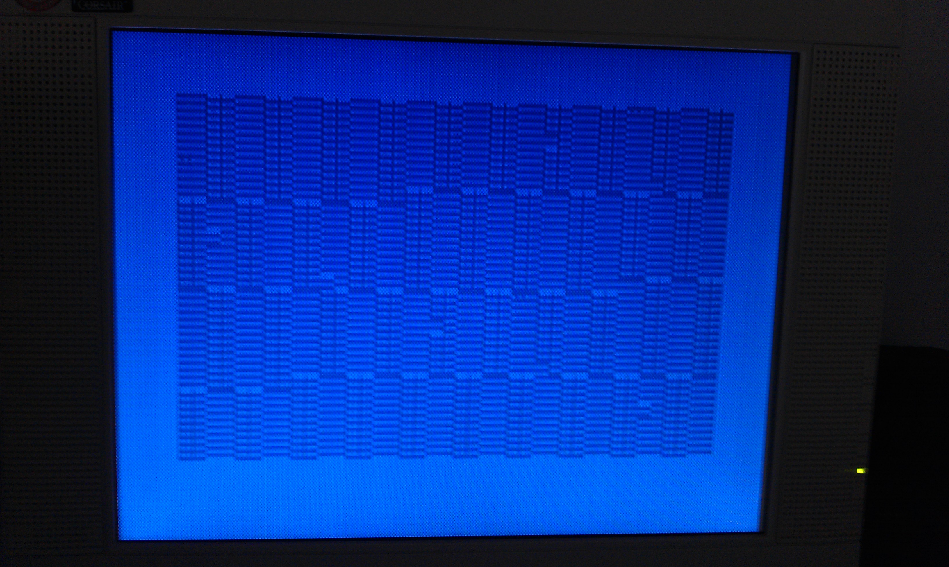
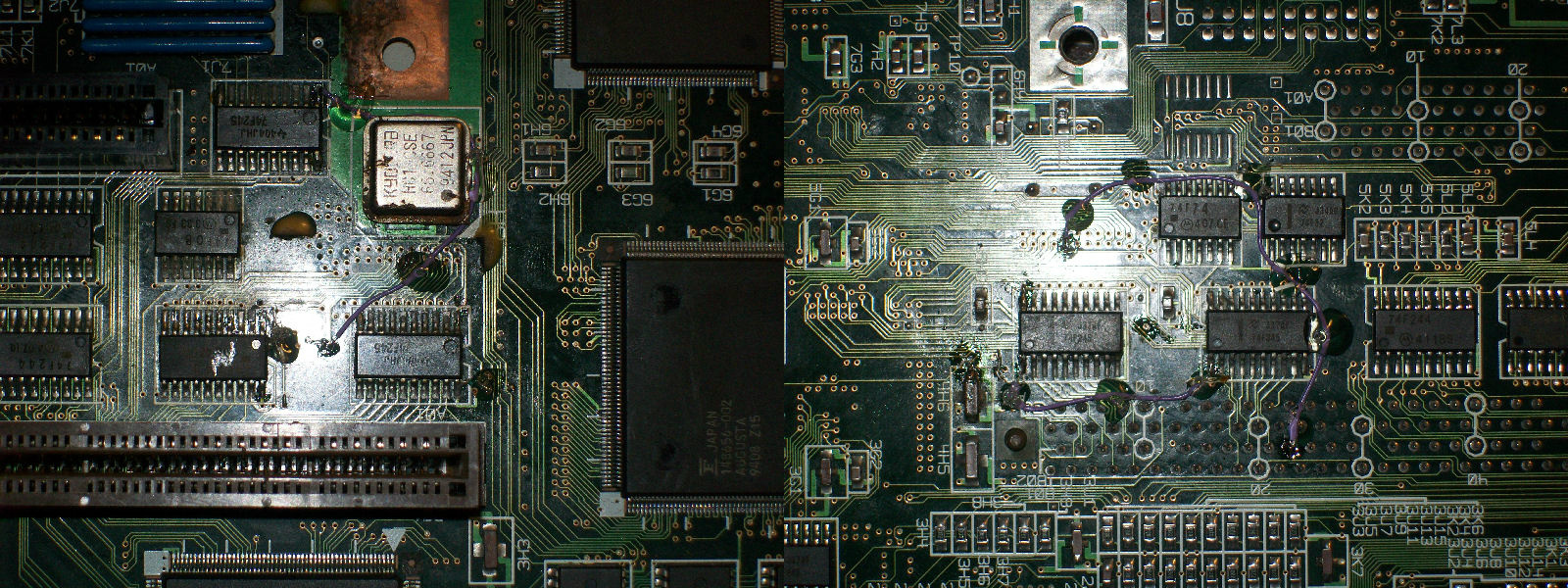
Powered it on and I got a solid black screen so was time to disassemble it.Motherboard was clean except for this:

capacitor_leakage

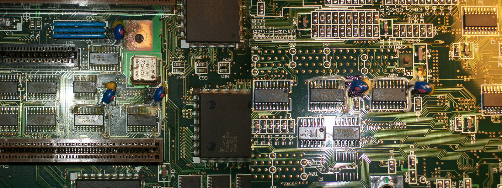
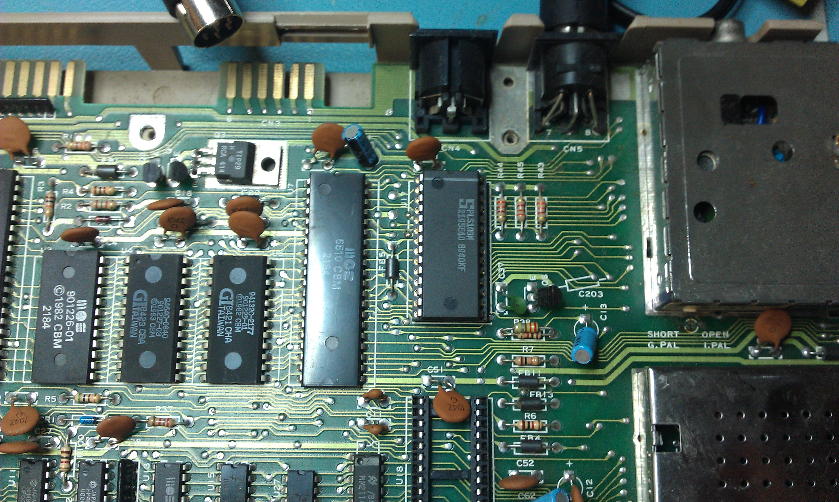
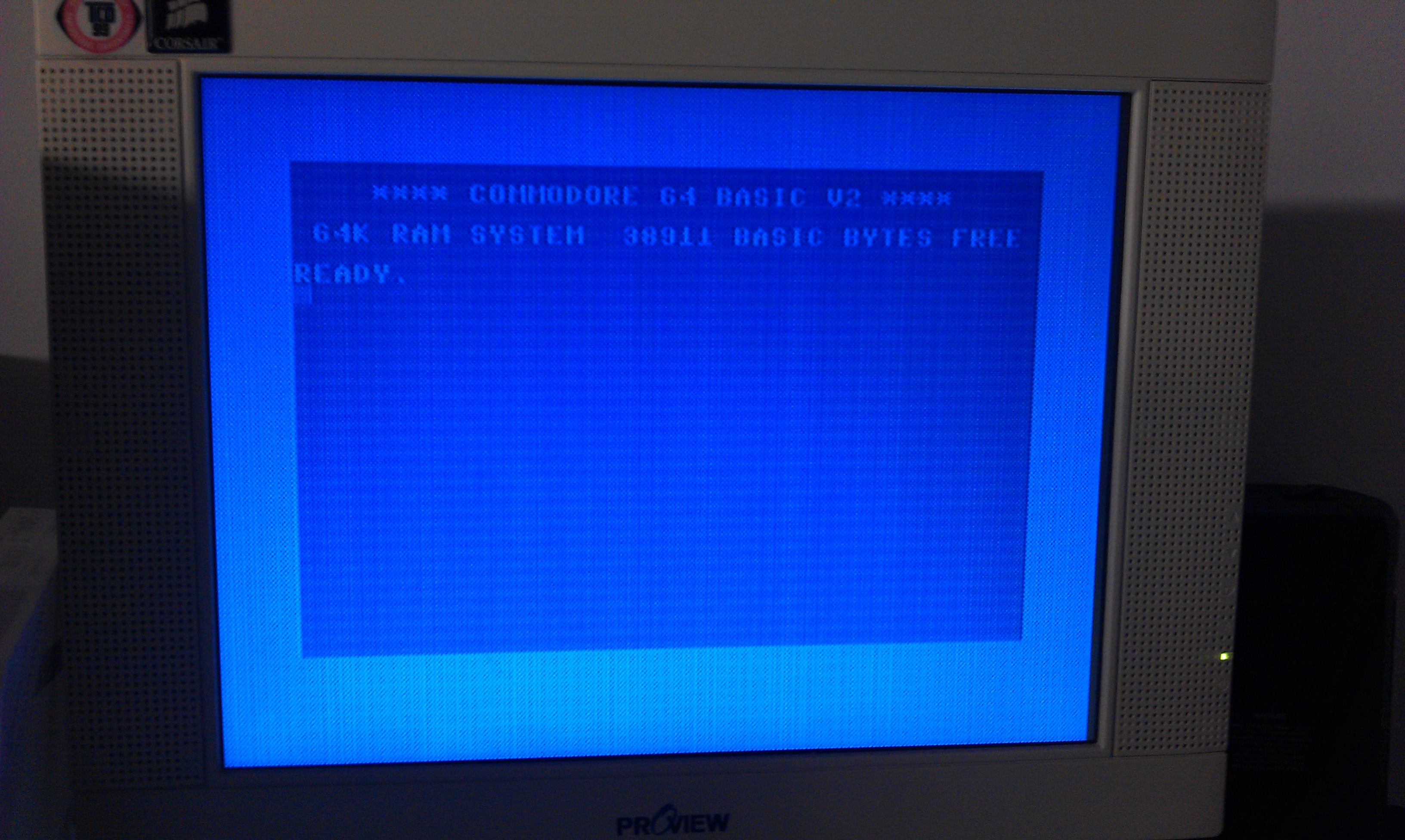
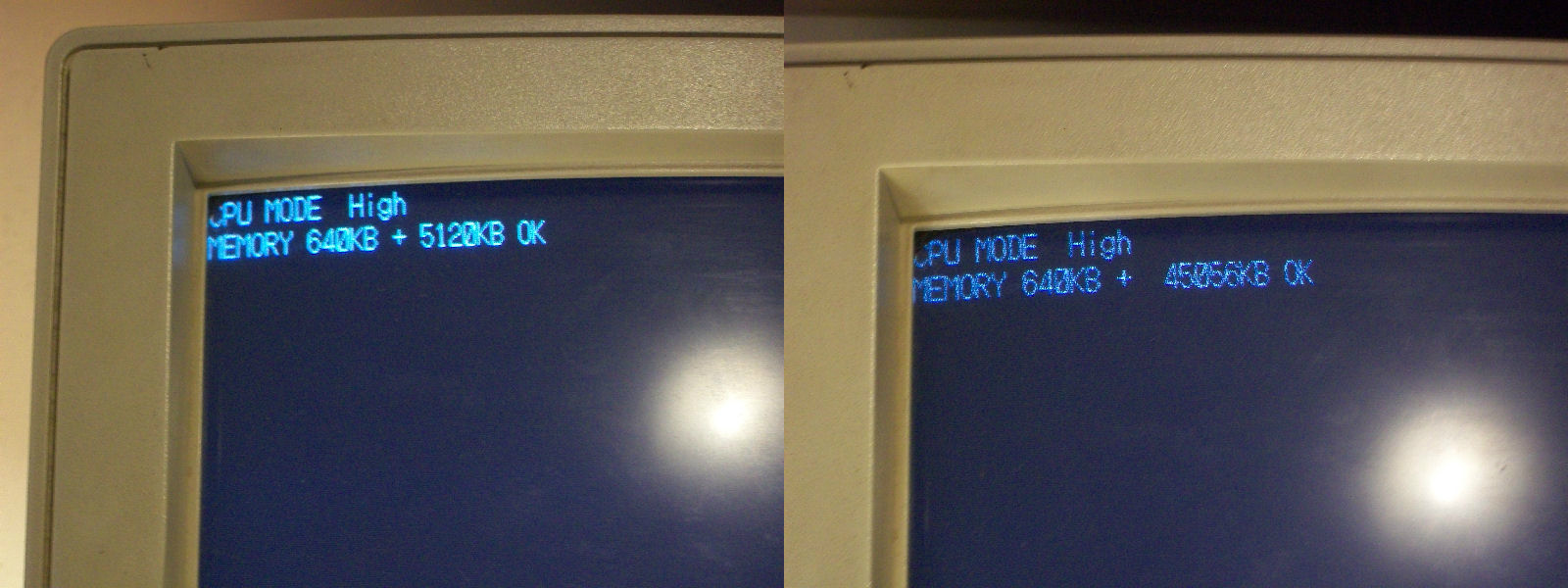
Surpringsly all electrolytic capacitors were  in good state for a machine with more than 20 years old but there was sign of corrosion near five 22uF 16V tantalum capacitors which leaked spreading their dielectric on pcb.This was most likely caused by the glue used to hold them in place that turned corrosive with age.These capacitors were mounted as decoupling on five 74F245 which are used for DATA communication between DATA buses.In this hardware they were interposed between four NEC 42S4800 DRAM chips and connector of the CPU riser card.So, with these premises, I was quite sure that fault was located in this crucial part of the motherboard.After removing the leaking capacitors and cleaning the circuit, I started to probe continuity between each pin of the five 74F245 and motherboard and , following a scheme that I had prefigured, I found that PIN2 of one of these was not connected to the CPU card connector like all other so one bit was missing and the system was halted.Jumpered the two points and finally system successfully booted:

memory_count_wrong

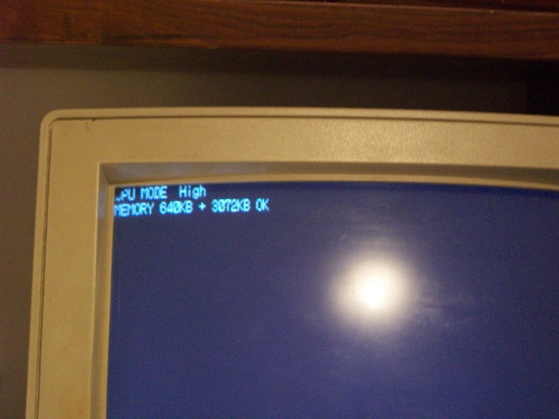
But immediately something sounded strange to me.According to its specs the PC-9821AP2/U8W model should have 5.6MB of default RAM  (first 640KB are conventional memory plus 5MB of extended RAM) while, as you can see from picture above, mine had only 3.6MB so I missed 2MB of them somewhere.Also using an addon RAM card didn’t change the amount of memory.So, something else had to be wrong.Luckily I had another same PC with a good motherboard and tracing it I found that the five 74F245 had PIN1 (direction PIN which select the direction of the DATA transfer) in common while in the faulty motherboard this was only for two of the TTLs.So, due this, DATA could not be transferred from all available RAM to CPU resulting in only 3MB in total.

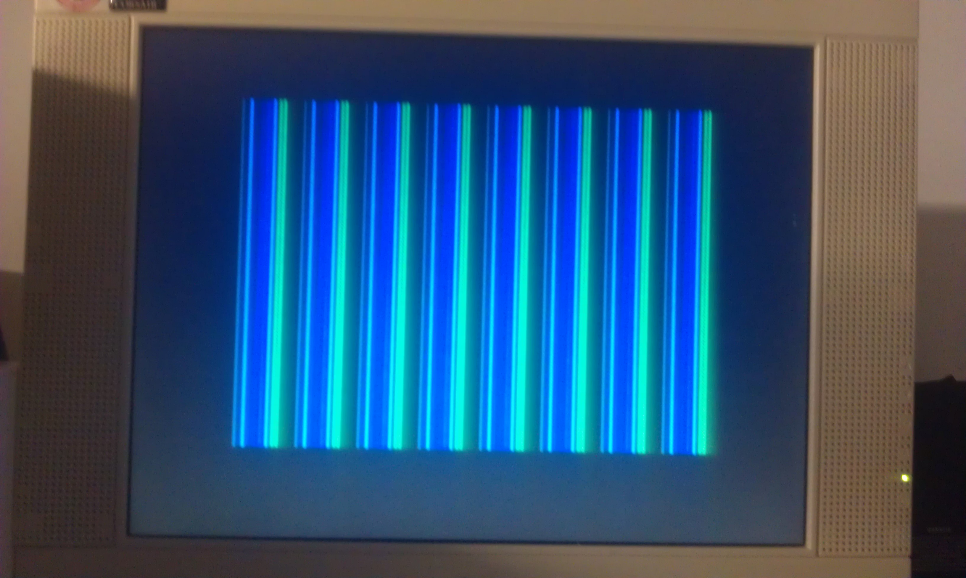
So I tied PIN1 all toghether with some AWG30 wire:

74F245_PIN1_jumpered

and the missing 2MB came back as well all extra memory of the addon card:

RAM__OK

Another job done.

 Posted by at 6:30 pm
Dec 312014
 

today I got a couple of Oric computers.
Ive been after one of these for some time now but prices have shot up of the last 12 months.
I couldn’t resist buying these two, both of them which required repair, as the price was right.
IMAG1141

First is red/black one.
I first started by removing the ULA and powering up to check voltages. I do this with Spectrum’s too as these early voltage regulators have a habit of going wrong with disastrous consequences.
With everything looking OK I refitted the ULA and power up. I was greeted with this screen.
IMAG1145

Ive read enough about the Oric over the years to know that the ULA is very hardy and the RAM is very poor. Ive also read that a fried ULA will usually result in nothing on screen at all.
I opted to desolder the RAM first.
There are 8 x 4164 RAM chips and on testing two of them failed.
I socketed and replaced the faulty RAM and I now have this
IMAG1147

The random writing is my doing as the keyboard is flat on the bench when testing.
Happy with this. I think the second unit has the same fault too.

Mar 312013
 

My mate bought a Spectrum+ off eBay recently and it didn’t work.
All we got on powering up was this

First thing I did was check the voltages. They all seemed fine so on with the next test.
The ULA was the only chip that was socketed so I quickly replaced it with a known good one. Still the same fault.

To save myself some time I thought I would desolder the Z80 CPU in order to use the Fluke 9010. Turns out the CPU was at fault and on fitting a new one we got this (bad picture, I know)

Anyway, I carried out the very simple composite mod and this is pretty much all done. Another Spectrum saved

 Posted by at 8:58 pm
Jul 282012
 

Saw this the other day on eBay and it was going for a sensible price with sensible delivery costs so I took a shot and won it.
On power up we got this

Never seen this fault before and as everything was soldered in I didn’t want to go down the route of swapping everything out.
I could not use the cartridge port or type anything in but I did have what looked like a flashing cursor. I also found, when I pressed the CONTROL key the screen flashed up with a nice multicoloured garbage screen which I have seen before with a dodgy PLA.
Whipped this out and burned a new PLS100 chip.

Now everything is back to normal (or is it?)

Whilst running some diagnostics I saw there was a fault on one of the CIA chips that displayed “INTERRUPT”yet everything seemed to be working.
Running a different set of diagnostics I found that the RESTORE key did not function. As the restore key generates an NMI this was probably what I was seeing.
I don’t have any spare CIA chips so this will have to stay as it is for now.

UPDATE: Thanks to a comment left by Rocky I revisited this today armed with schematics. Found a completely knackered 556 timer chip that just so happens to control the NMI from the RESTORE key. Replacing this fixed all my problems.
Lesson learnt. Don’t assume you always know what your talking about!

Thanks to Rocky for making me look at this again

 Posted by at 7:12 pm

Spectrum divIDE repair log #2

 Computer Repair Logs, Repair Logs  Comments Off on Spectrum divIDE repair log #2
Jul 092012
 

Another divIDE repair today.
Very simple, with the device connected I got this

As Ive found with all of the divIDE boards that Ive repaired the EEPROM was blank. A re-flash sorted this problem out.

There is apparently a reason why this keeps happening and has got something to do with the way the Spectrum regulates power at startup.

 Posted by at 4:38 pm