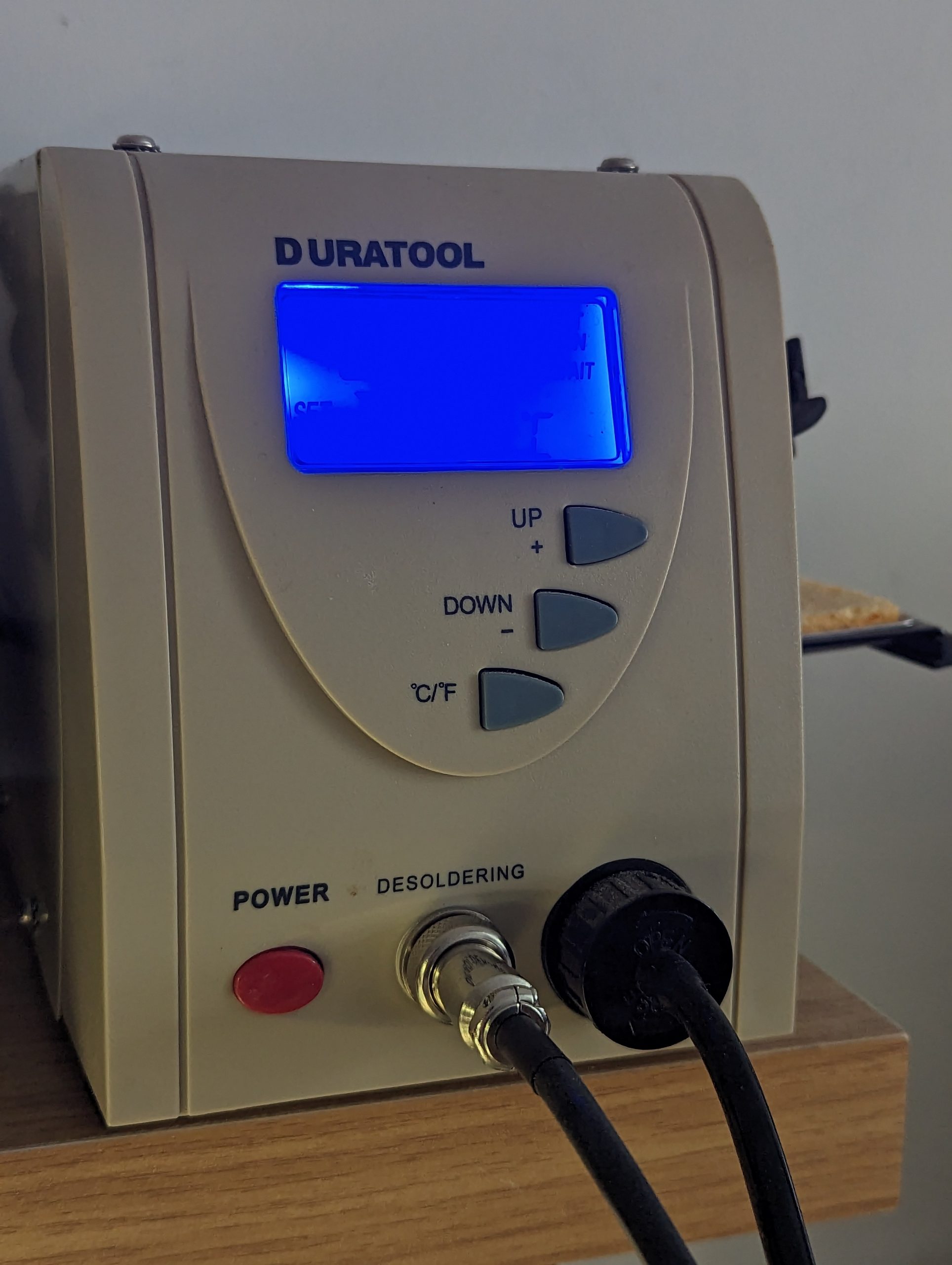
I’ve used this cheap desoldering station for many years now. Despite its quirks and constant demand for cleaning its been a great work horse.
The an immovable blockage happened recently and I just couldn’t clear it so decided it was time to replace the element. I thought I had a spare from years ago but turns out I have ordered the wrong part.
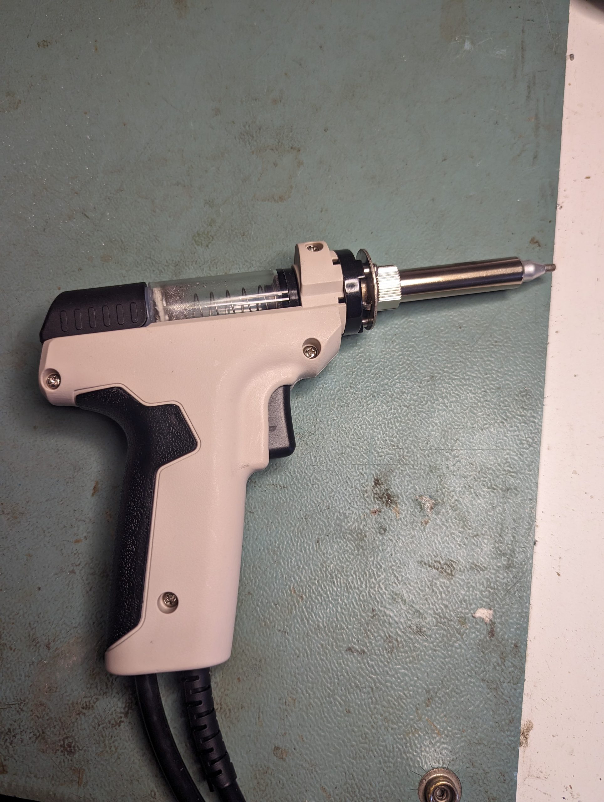
Looking for the correct part I found it was almost the same price to buy a new gun part itself and I wouldn’t have to mess around slicing the wired inside.
New gun came and all was well in the world for around 5 minutes when the unit got stuck in a reset loop.
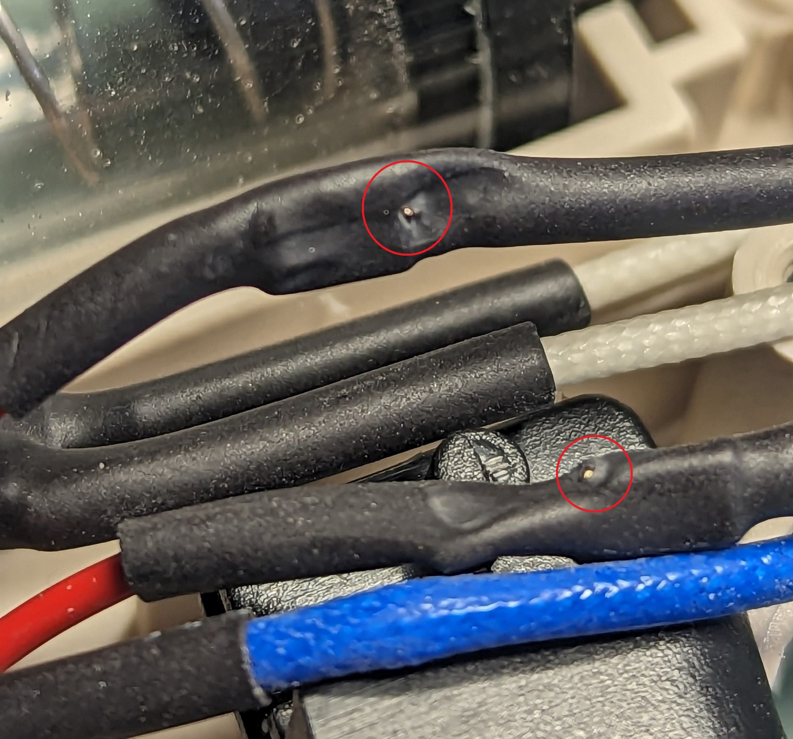
Obviously there was a short somewhere so set to work checking resistance until I found a shorted element.
All the wires for this thing are very tightly routed and when i pulled them out I found this
Those small breaks in insulation from being sandwiched together so tight caused my issue. A little bit of insulation tape later and I was back in business
Not really much of a repair log but its just something I’ve been up to recently among other things.
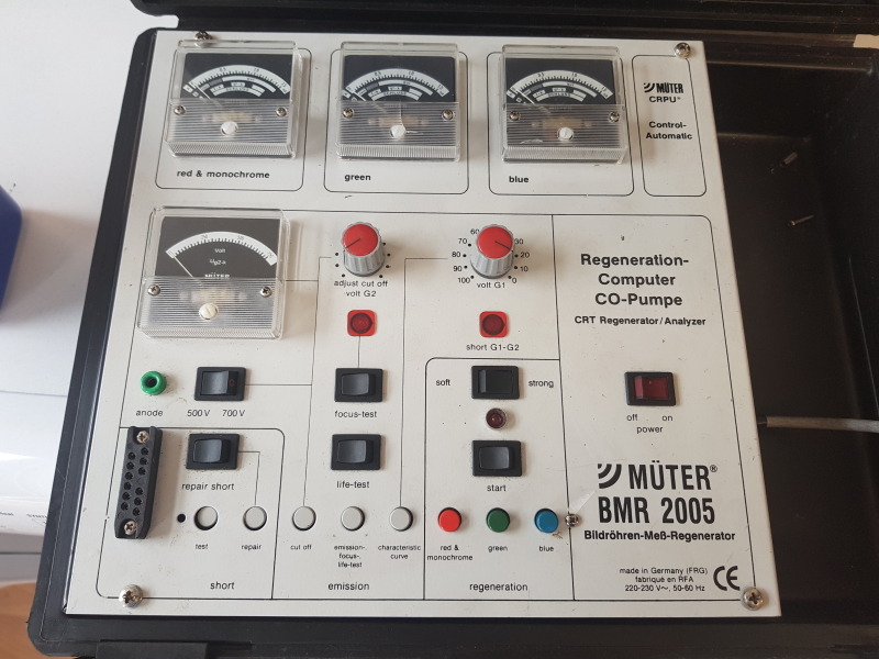
Saw this recently on eBay for a cheap cheap price.
I didn’t necessarily want the unit itself but more the CRT adapters it came with but the price was right.
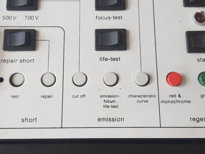
First pass on the visual inspection showed that something wasn’t quite right.
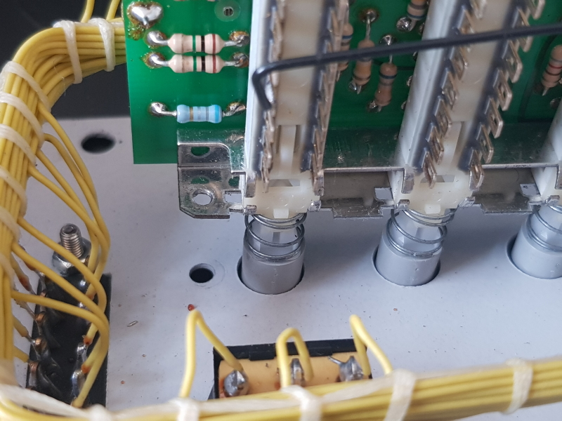
Removing the 4 screws on top lets you get into this thing and there is a spacer post and screw lying in the bottom which is clearly from the PCB housing all those buttons.
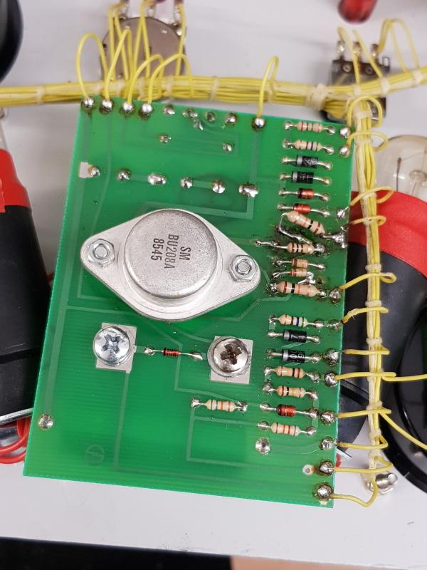
While fixing this in place I had a look over everything else and found something a little worrying.
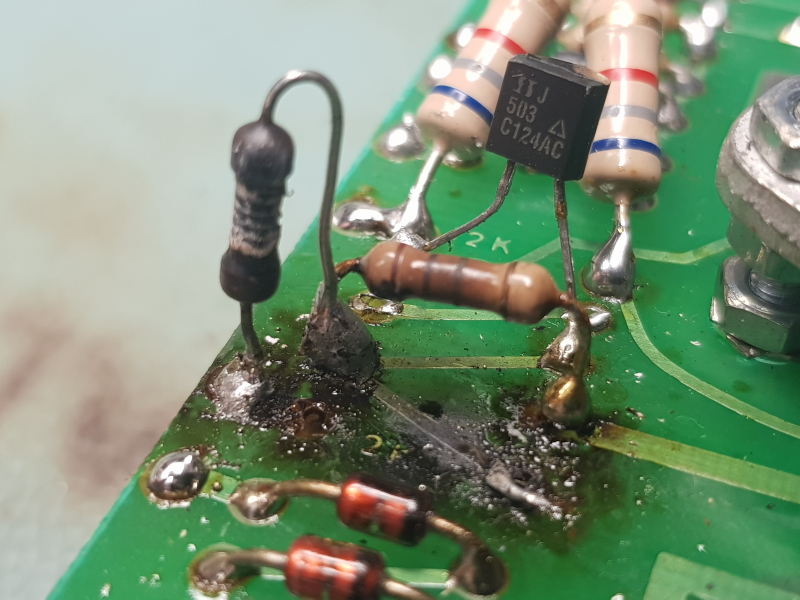
The crispiness aside this is not standard. There are 2 diodes missing and replaced with a transistor with the middle leg cut off, a lot of the traces are gone due to the charring and the 10K resistors have been replaced for two in series and are also the complete wrong value.
I just opted to remove all of this and replace with what it should be.
There is a schematic for this in the back of the manual so could check the values and the connections but I also have the BMR 95 which I took a look at as well
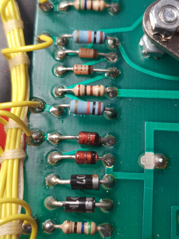
Here is what I ended up with
Its by no means a neat job but short of reproducing that little PCB its pretty much the best I could do given the amount of damage.
I checked all the other components on this and they tested good.
I have now tested this on one of my monitors and compared the readings against my other unit and they are all good so Ill consider this one fixed.
I’m not dead!
Some time ago I scored a great deal on eBay for a Data I/O 29A setup with a load of modules and manuals.
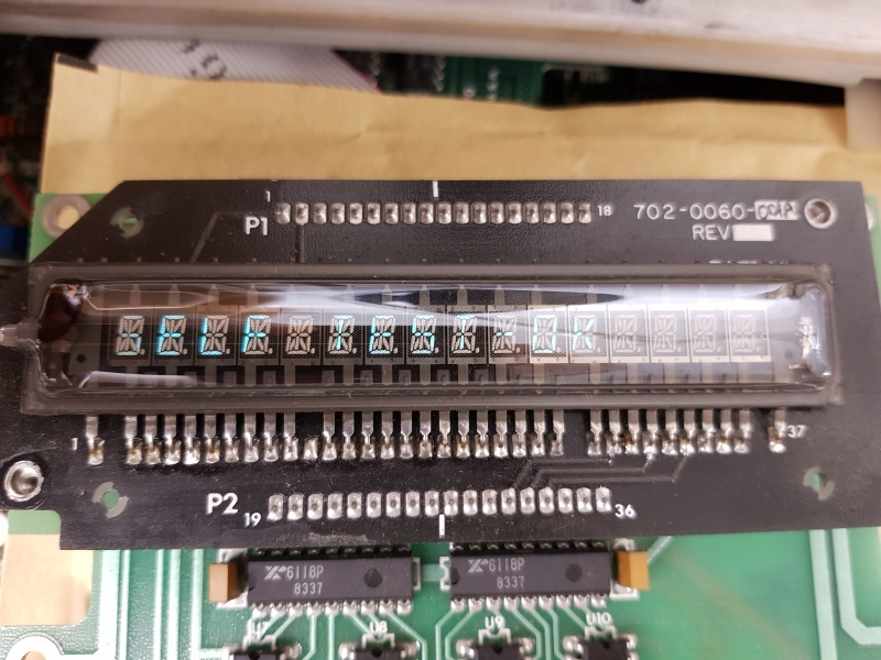
Pretty much everything worked great apart from the display was really dim.
It doesn’t look too bad in the picture but it looked much worse in real life
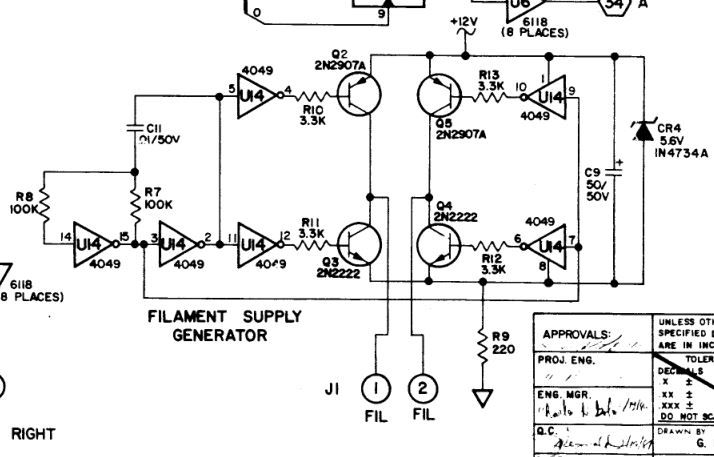
Schematics are readily available for the unit so fault finding was fairly quick.
With the display being dim my initial though was a voltage issue and the schematics have conveniently labelled the area up as “FILAMENT SUPPLY GENERATOR”.
Using the scope I could see straight away the CD4049 hex inverter at U14 was not inverting at all.
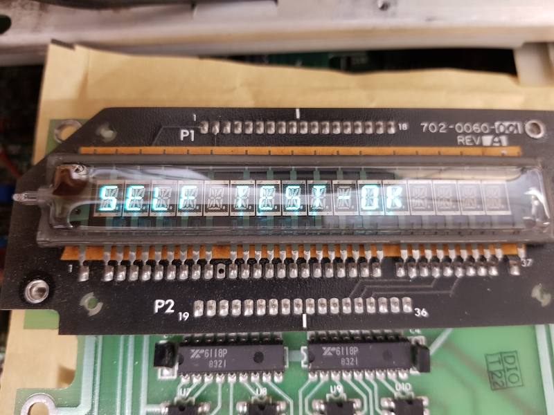
Simply replacing this fixed the fault
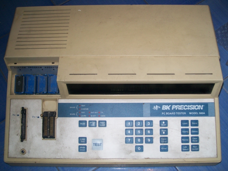
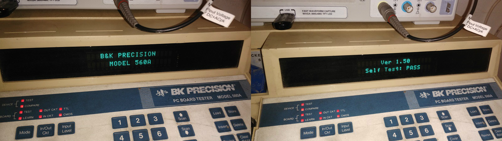
Some days ago I wanted to test some RAM chips from an arcade PCB using my B&K Precision 560A tester :
B&K precision 560A IC tester
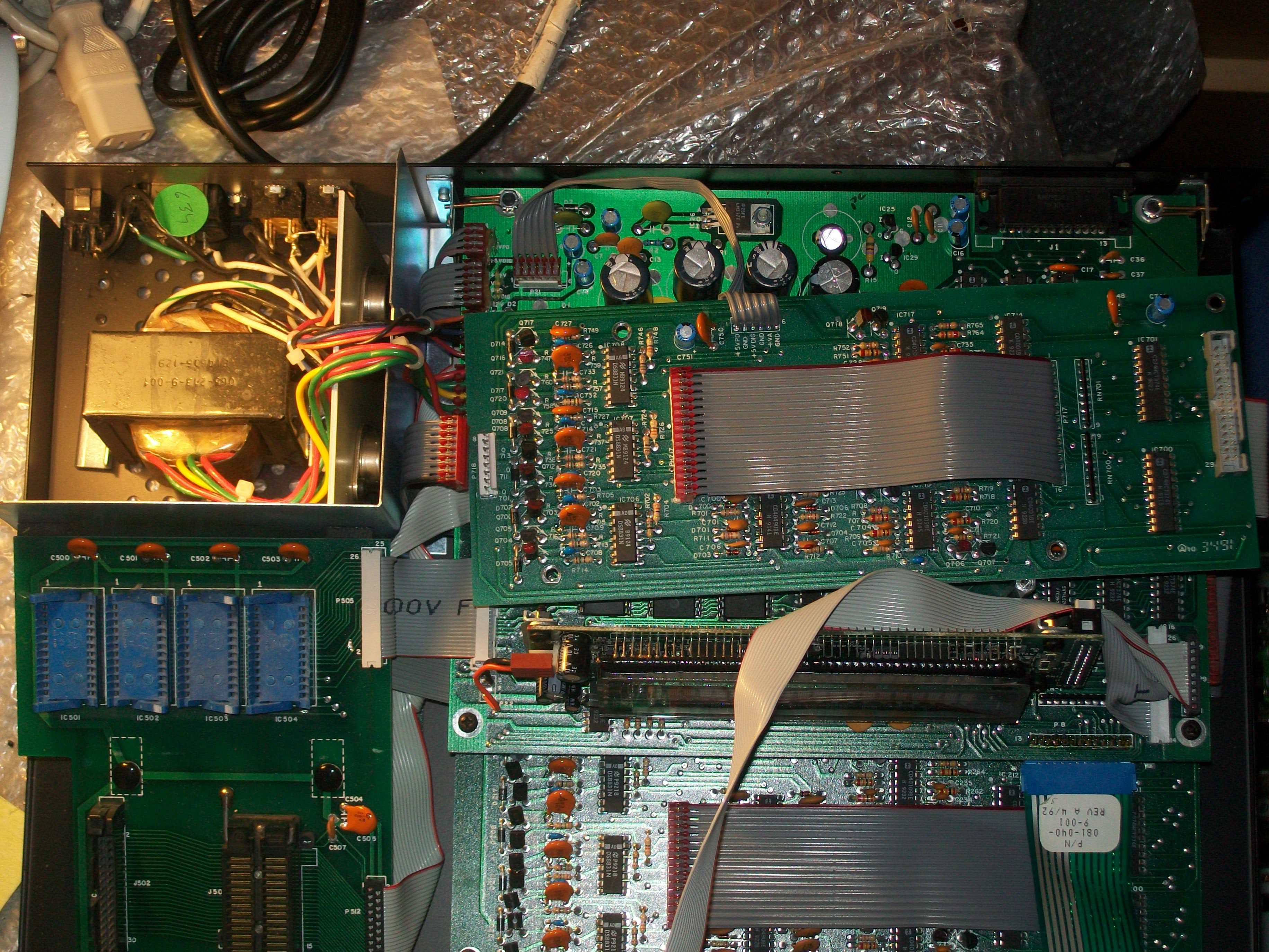
For the uninitiated this piece of equipment allow you to do out-of-circuit and in-circuit testing of many ICs like TTLs,RAMs and ROMs thanks to an extensive internal IC library.I often use it during my repairs but in that day it suddenly died, no sign of life, nothing came up on display when I powered it up.For first I checked the main fuse and it was good so I decided to open the unit:
Its internals
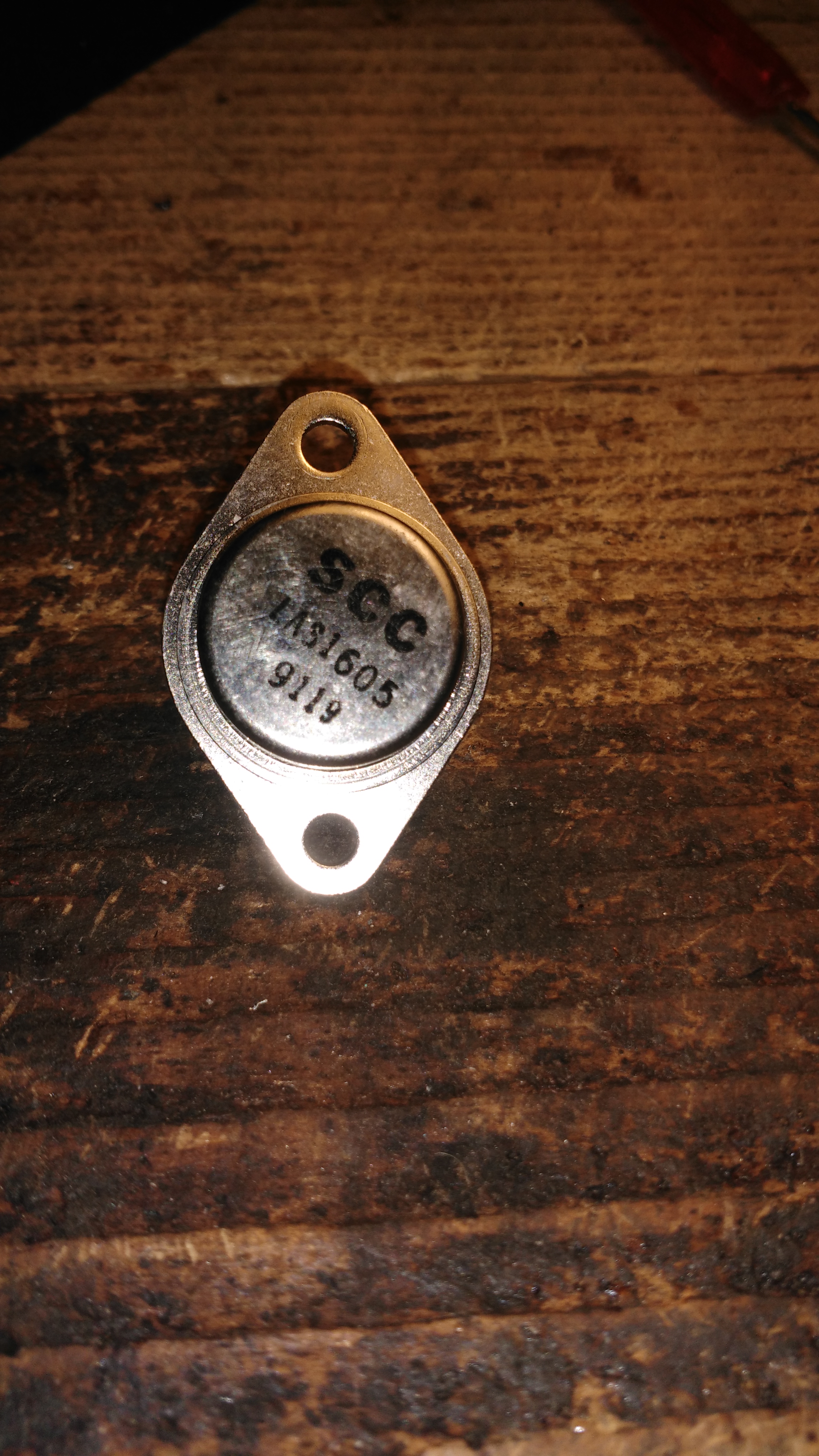
Having no schematics I started my troubleshooting from upstream checking the big transformer just after the AC input, voltages were present on its secondary coil.Following the path I figured out the AC voltages are rectified by a circuit on one of the PCBs.In particular the rectified +12V is then regulated by a couple of ‘LAS1605’ fixed +5V voltage regulators (in TO-3 package) mounted on a big heatsink for providing +5V to the circuitries on the other boards:
Two LAS1605 fixed +5V voltage regulators in TO-3 package
I probed the inputs of both and +12V was present:
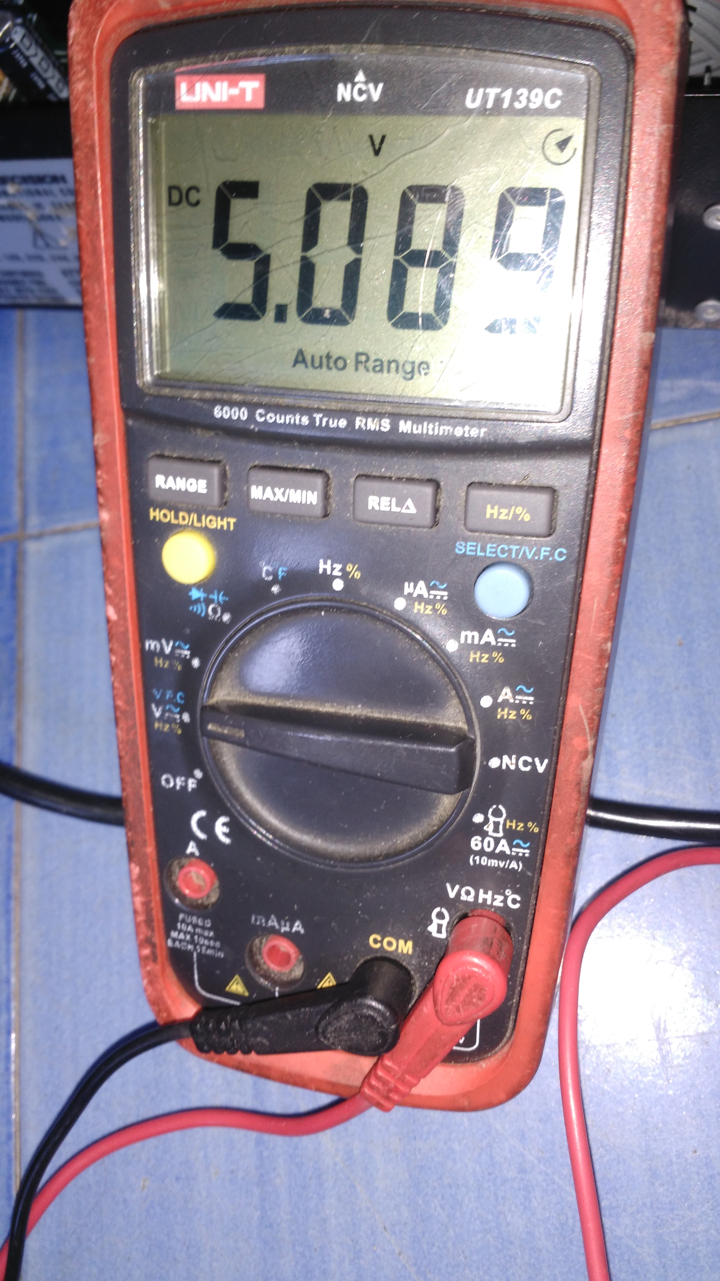
As well as +5V on the output of one regulator:
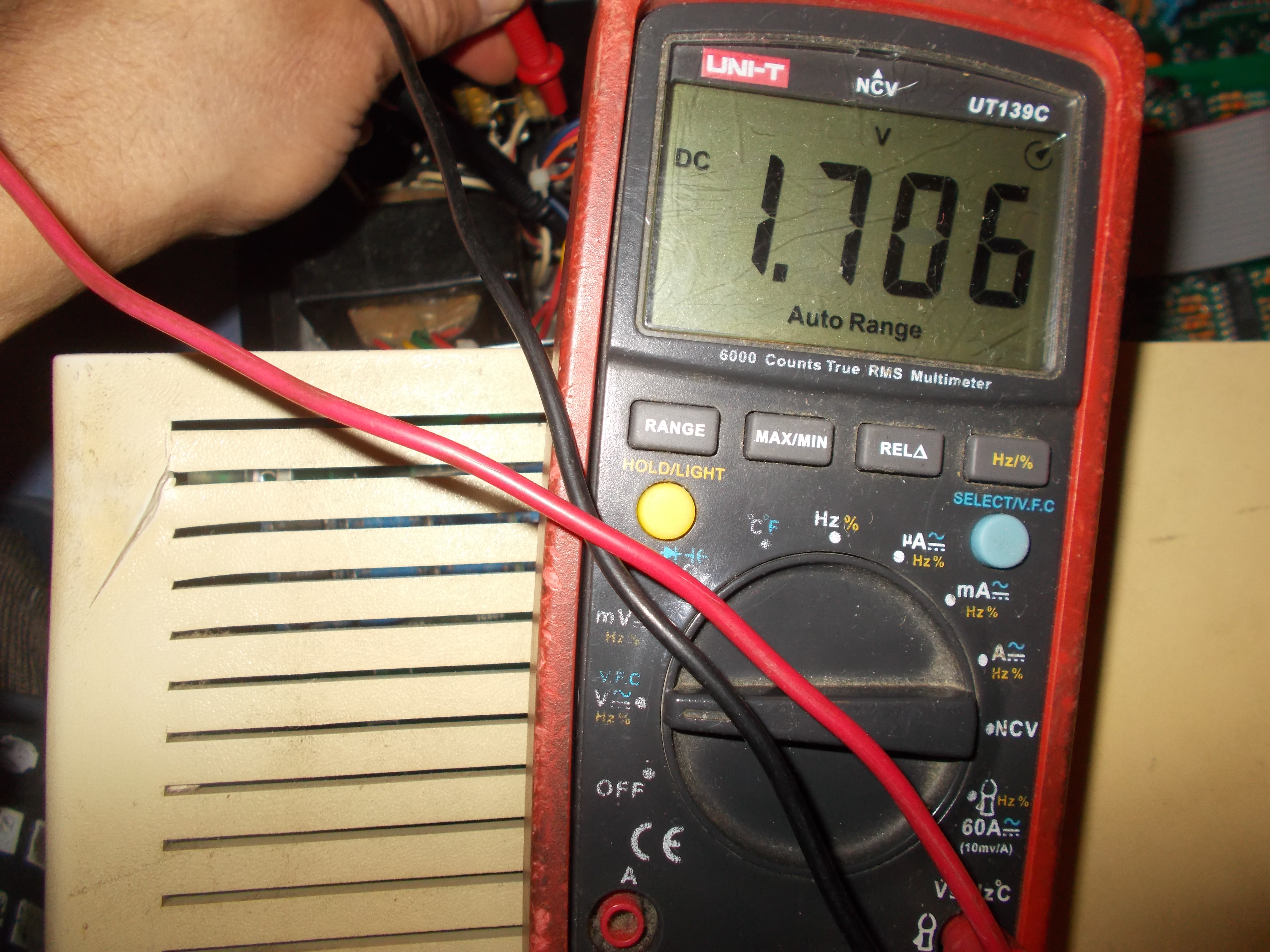
But the other one was giving only +1.706V on its output, too few for correct functionality of the logics on PCB:
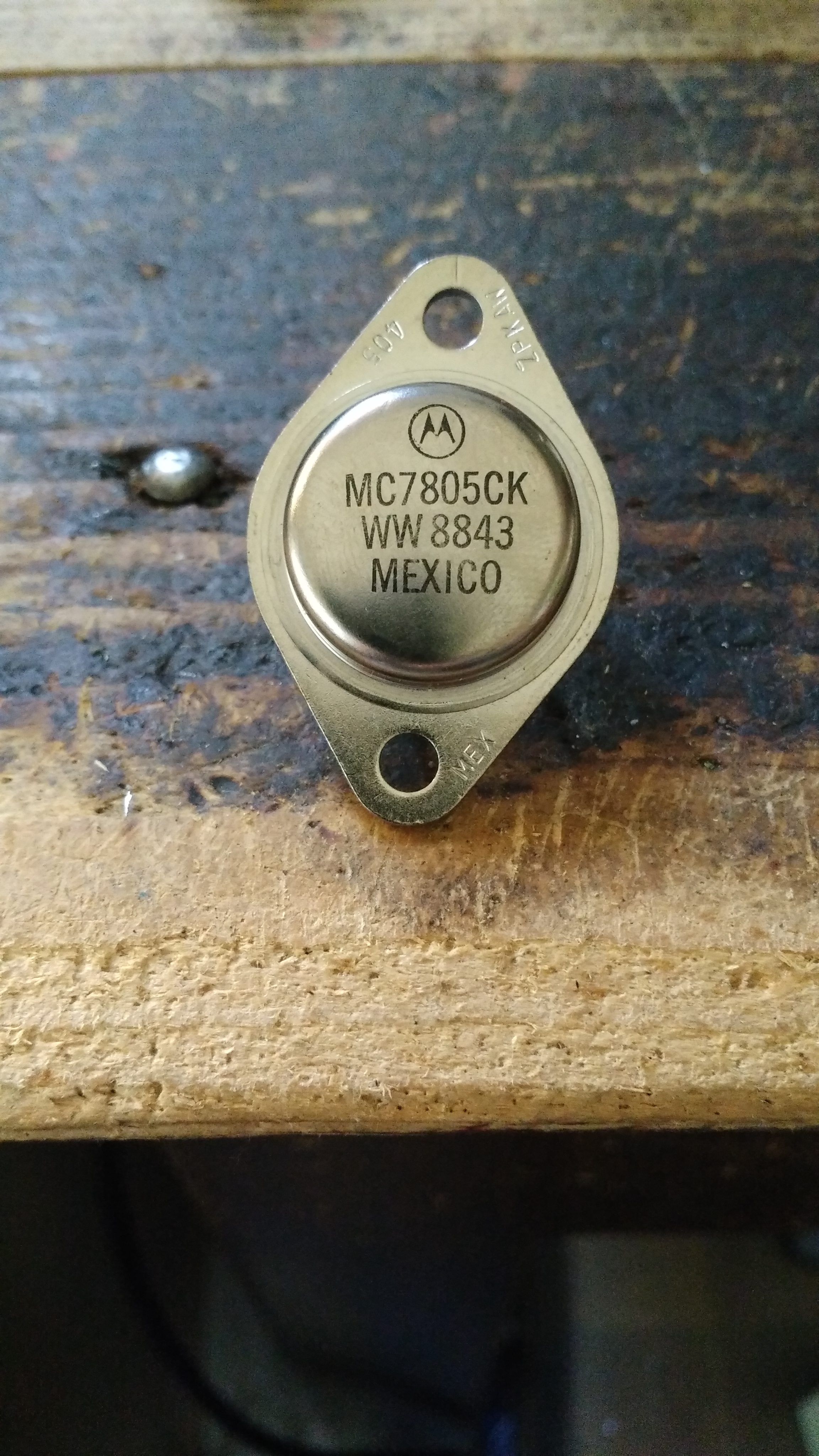
I looked online for buying a ‘LAS1605’ +5V voltage regulator or a compatible one but found only few at not really cheap price.Then, as a last resort, I asked my local electronics shop, they surpringsly had in stock some TO-3 ‘MC7805CK’ which is a perfect drop-in replacement (although it can deliver up to 1.5A output current against the 2A of the ‘LAS1605’ but this is not really an issue since I don’t think the tester can draw more than 1.5A during normal operation)
MC7805CK used as replacement
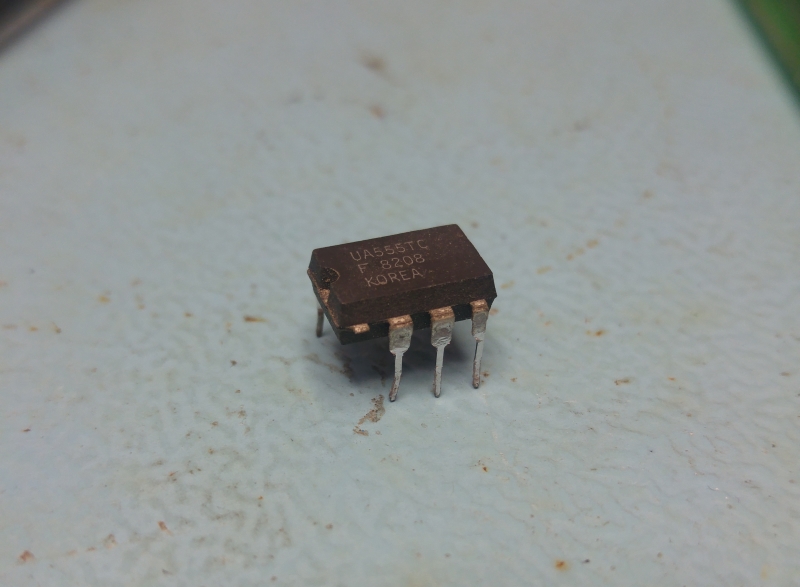
I pulled out the suspicious part:
The culprit in all its loneliness…
I swapped the spare in and was welcomed by this :
BK560A lives again!
My BK560A rised from its grave! Not too bad for a 2-euro repair! (as much as the replacement part costed…)
I bought this setup from a good friend quite a few months ago now. I knew it needed some attention when I bought it.
On power up I got this most of the time
No response from any inputs from the keypad.
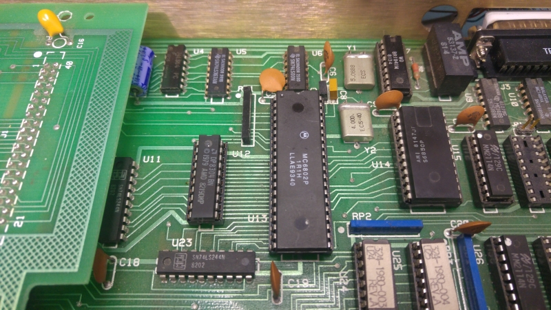
The keyboard generates an interrupt for the 6802 CPU. Using the scope I could see the /IRQ signal was being asserted.
I checked all of the ROM’s and found no issue and also checked to surrounding logic and found no issue.
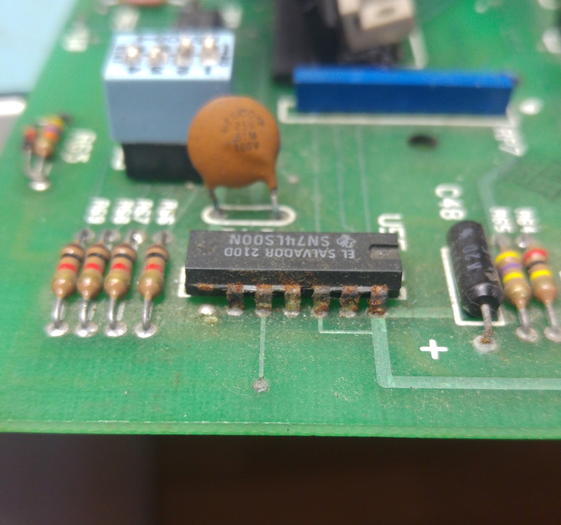
Looking around the main PCB I found a couple of problem areas.
As you can see, both of these chips had some corrosion. I replaced them but they made no difference to the problem I had so after a while I came to the conclusion the CPU must be bad.
Searching eBay turned up nothing UK based so I fired off an email to my friend, Purity to see if he had a spare I could buy. He had one and said I could have it.
And now I get this
Problem solved.
Next issue was with the Unipak 2 itself.
I could successfully select and read chips but the data being read back was a little wrong.
Reading a few carefully selected addresses of an EPROM I found that bits 2, 3, 4 & 5 were stuck high.
Looking at the schematics I quickly came to a potential problem area.
You can see from the schematic above that the LM339 comparator is responsible for those exact bits.
I removed the chip and tested it out of circuit. The chip failed and I ordered some new ones.
With a new one fitted everything was back to working status.
I’m really happy to finally have this in my collection and working.
Massive thank you to Purity for his generosity. He has been very kind to me recently and also a great help. I hope one day to be able to return the favor.