Operation Wolf repair log #3

 PCB Repair Logs, Repair Logs  Comments Off on Operation Wolf repair log #3
Apr 102020
 

Another few Operation Wolf boards in at the moment. This one is from Unit504.

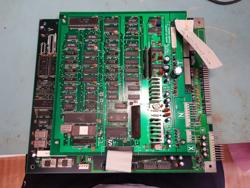
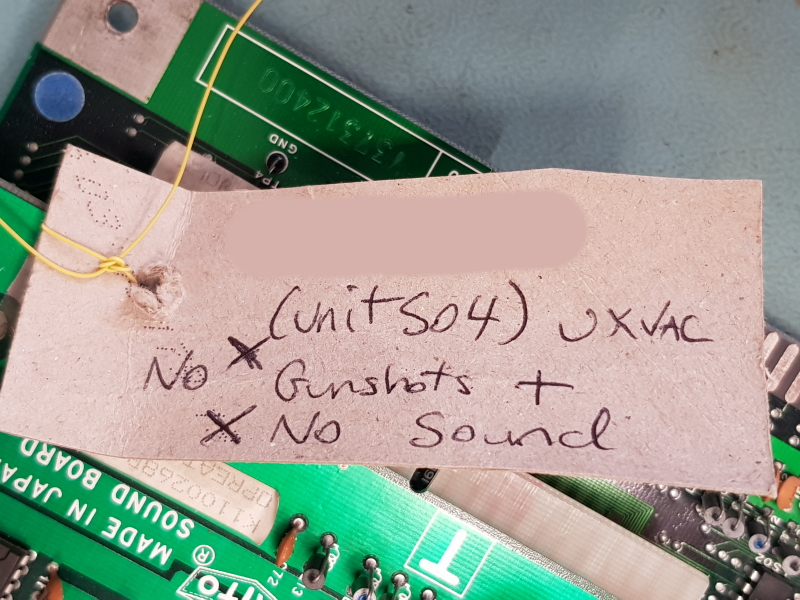
There is a nice little tag on this telling me the faults which really helps me keep all these boards together and where to start looking.

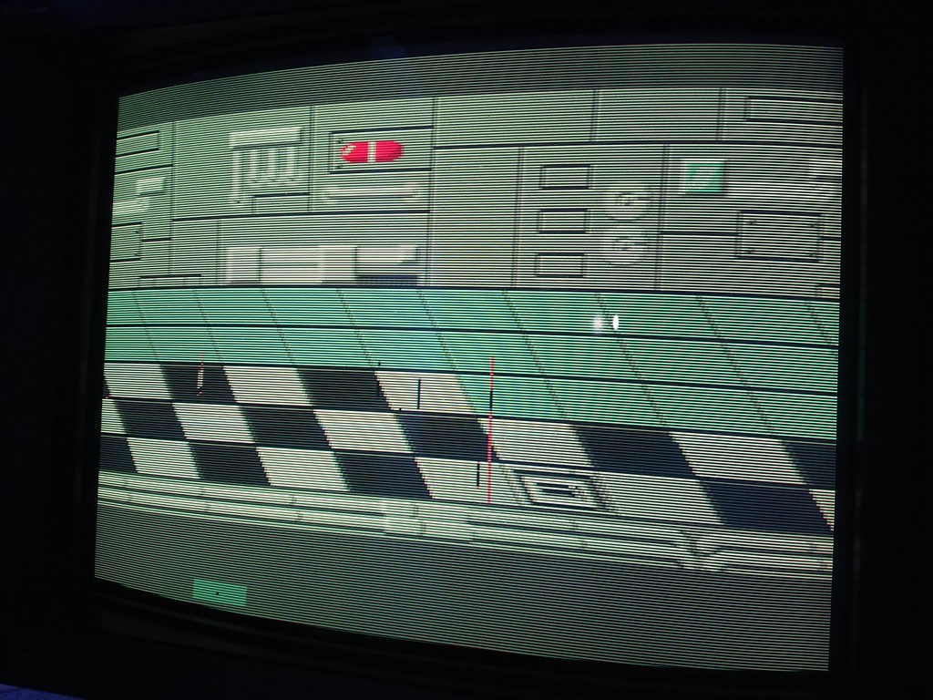
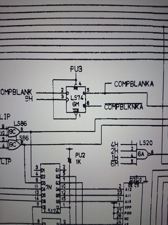
First job was to look into the gun shot register issue.
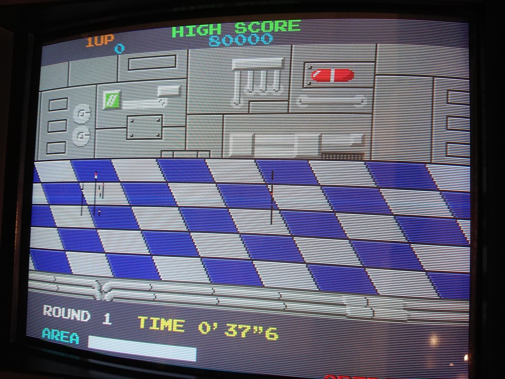
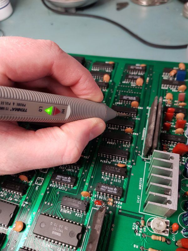
I did a quick test and could see the screen flash when the trigger was pulled so I knew that wasnt the fault
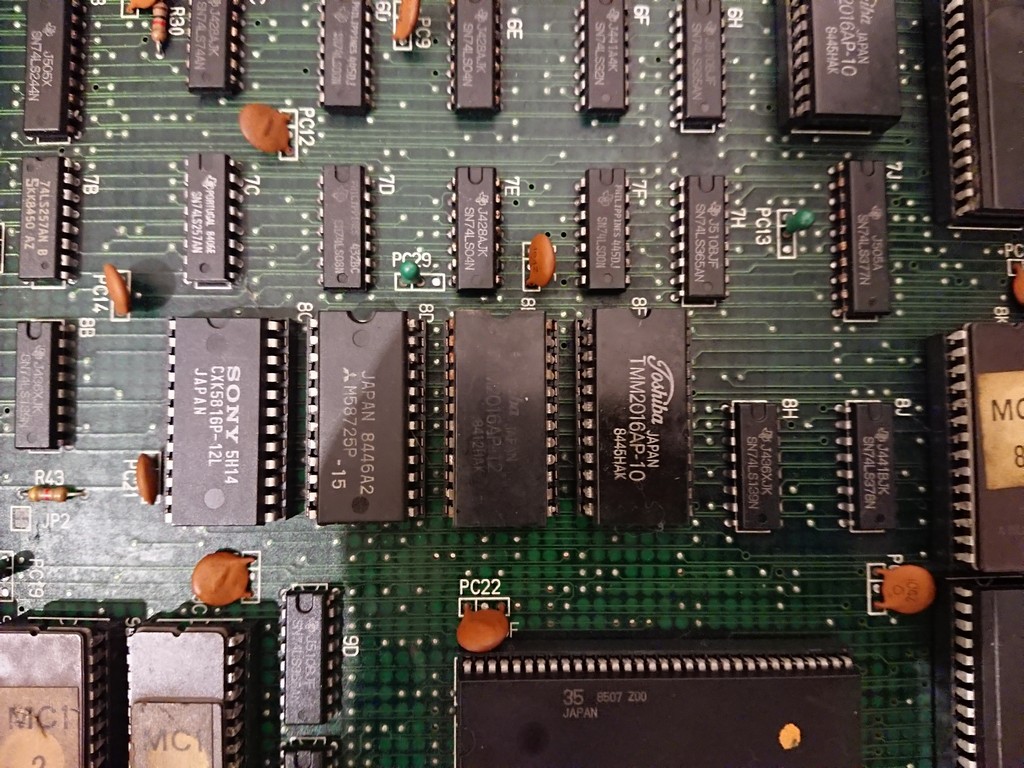
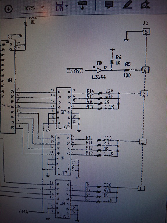
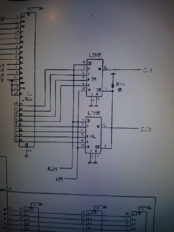
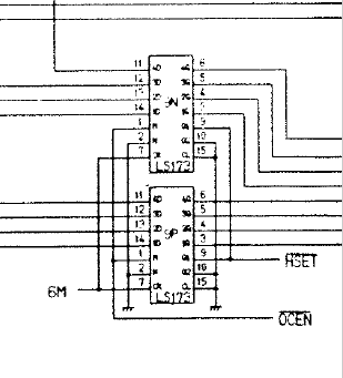
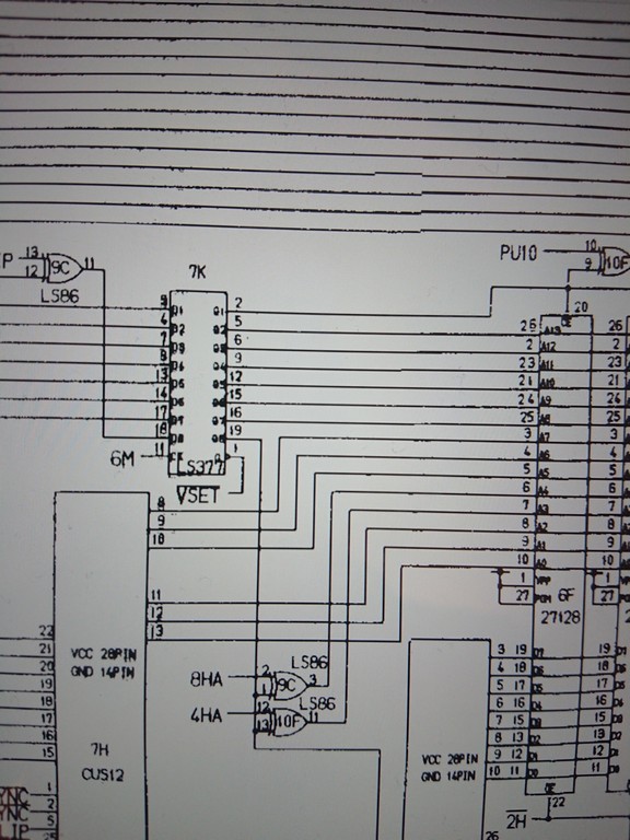
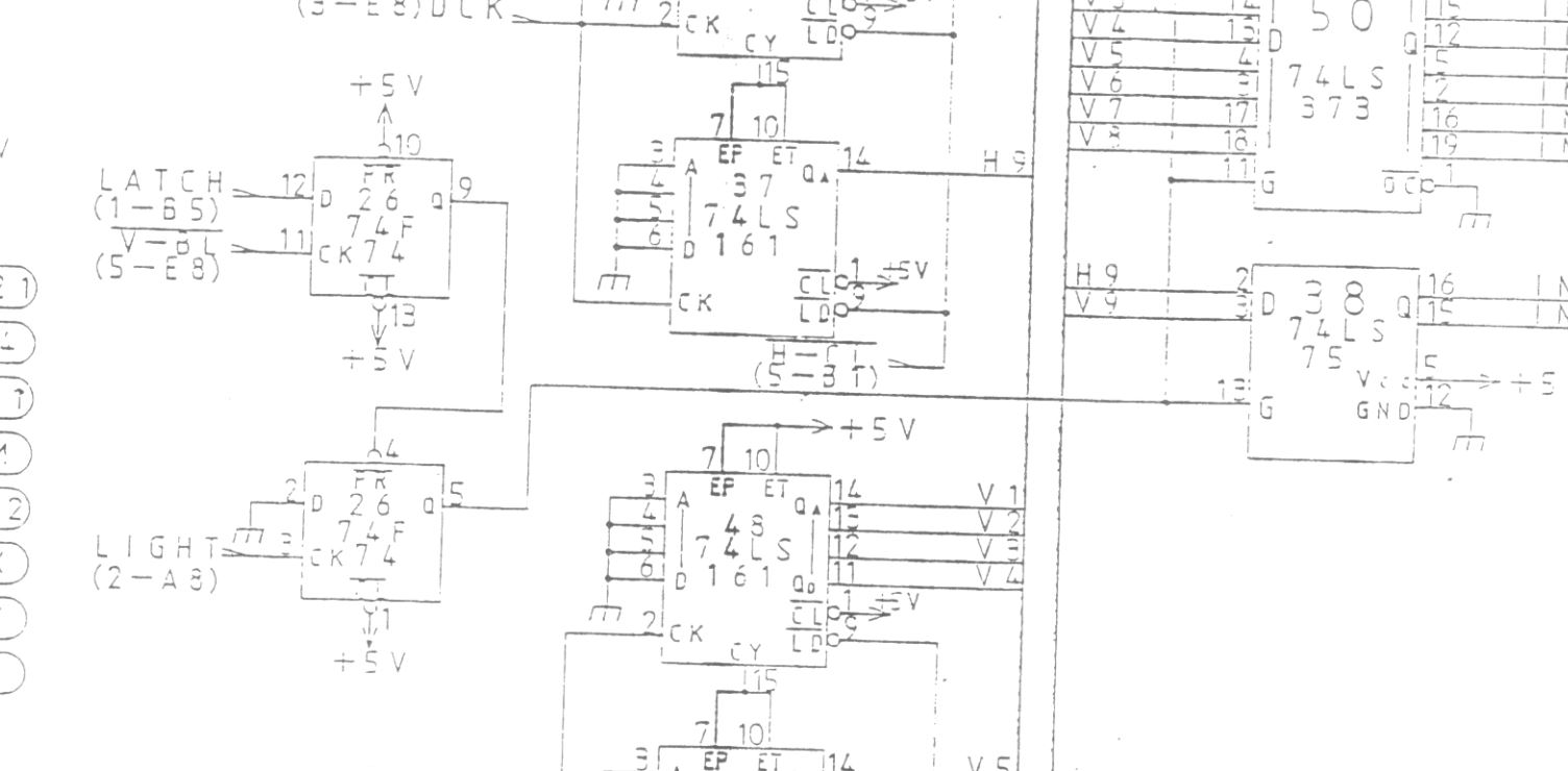
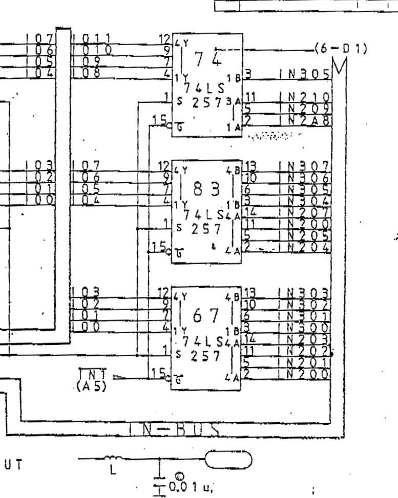
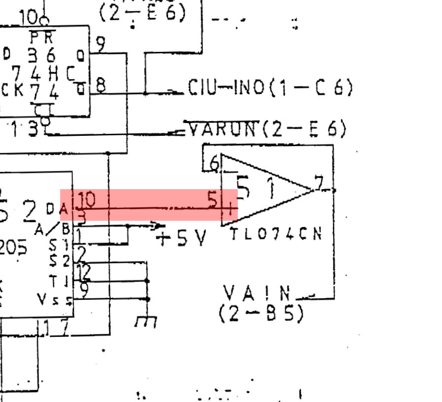
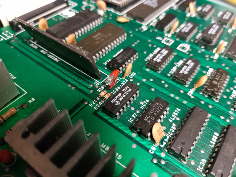
Following the circuit I come to the 74F74 IC which is used to latch the gun co-ordinates.

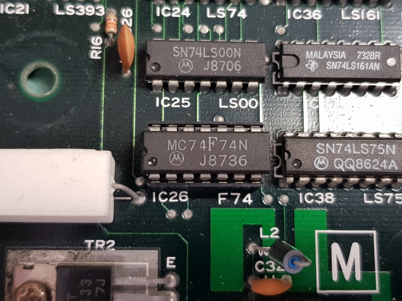
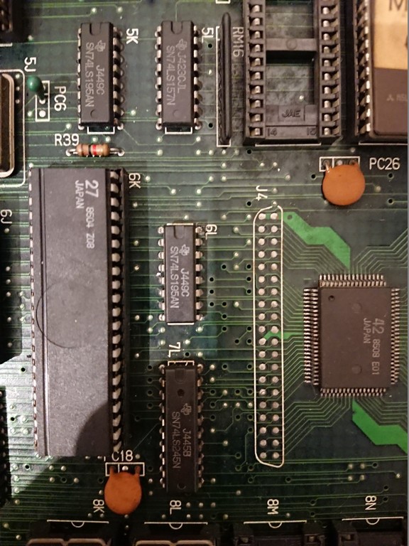
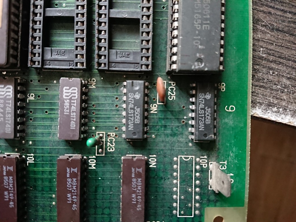
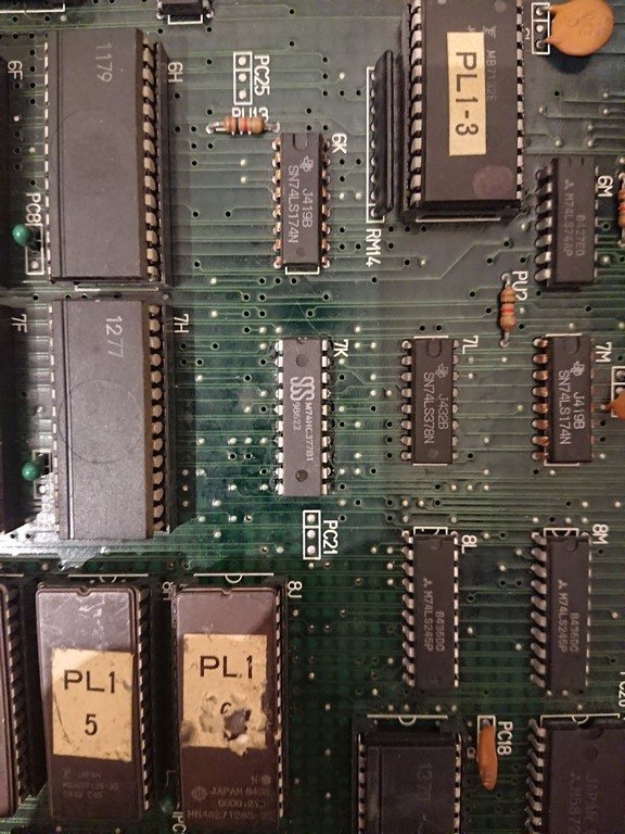
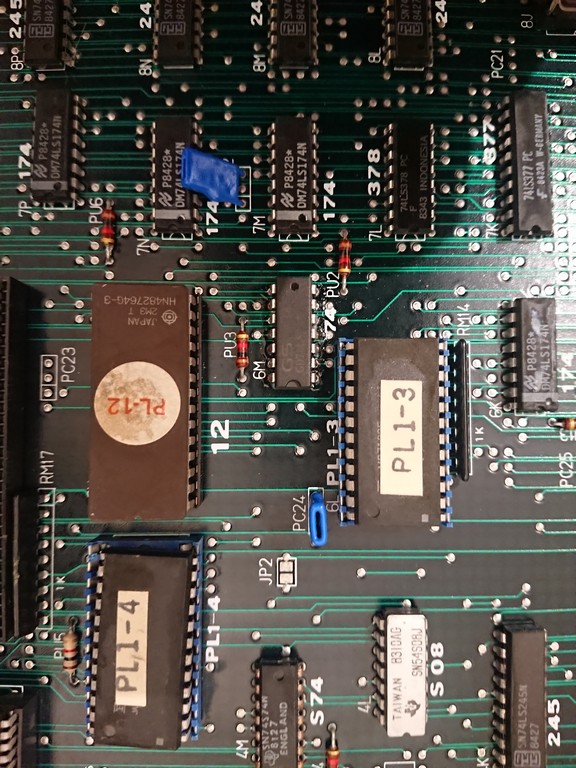
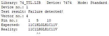
I normally wouldn’t start looking at this part but it was already socketed so decided to pull the chip and test it. It failed an out of circuit test.

I replaced this with a 74ALS74 and it seems to be be fine.
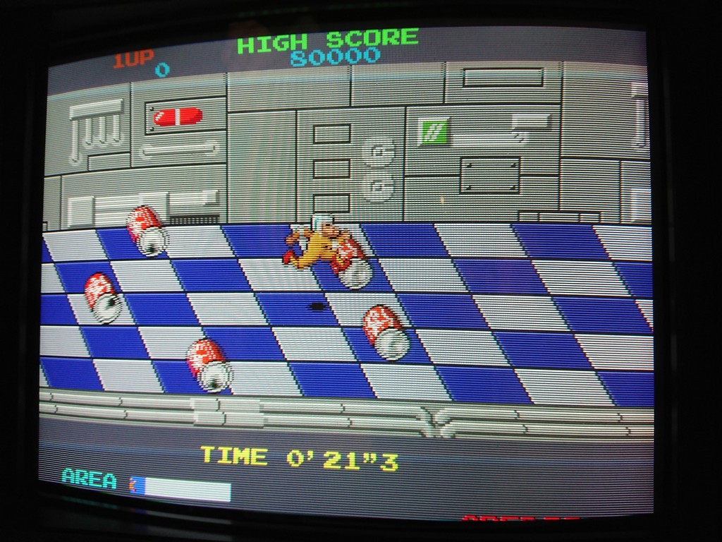
Now all the gun shots register as expected.

Next onto the sound.
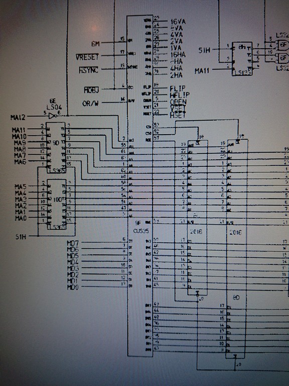
None of the sounds were working at all and I didnt believe that all the seperate circuits for making sounds would be dead so looked a bit closer at the CPU side of things.
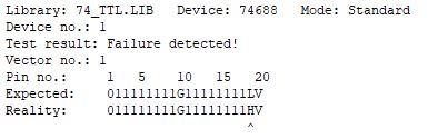
First off I checked the ROM and it dumped out fine.
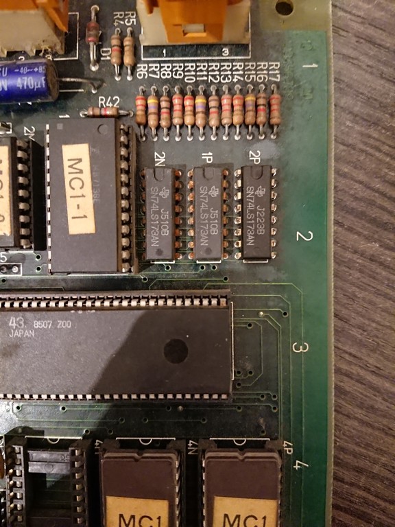
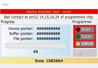
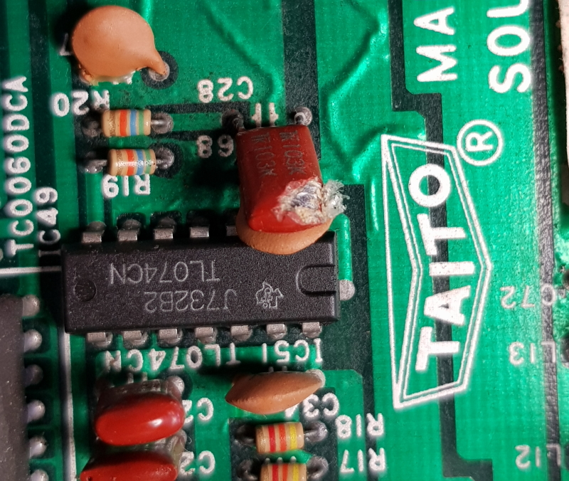
Next the RAM. An inspection of the RAM showed signs of corrosion

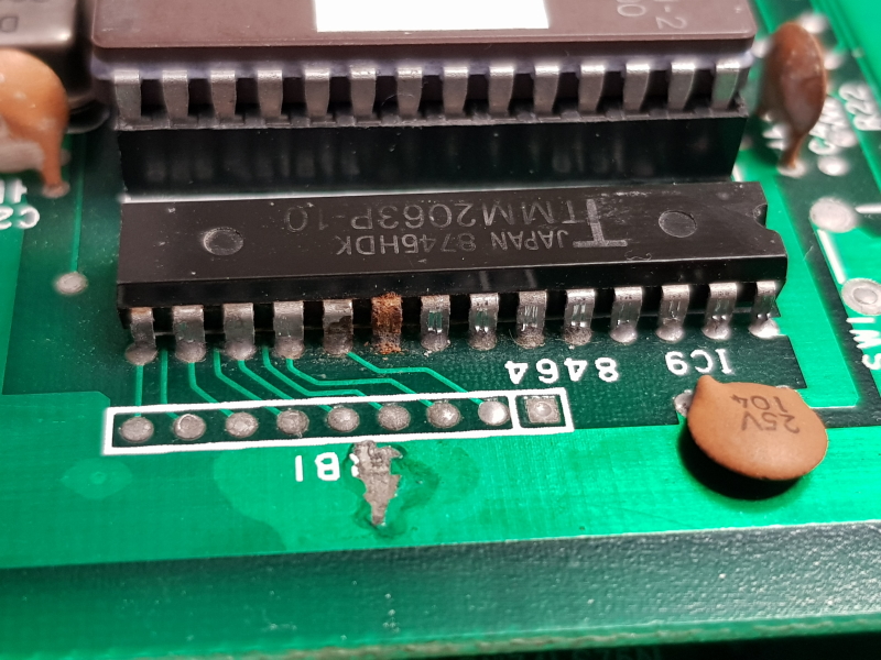
I removed and tested it and thankfully it failed

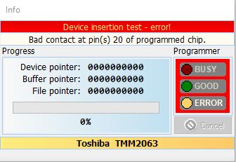
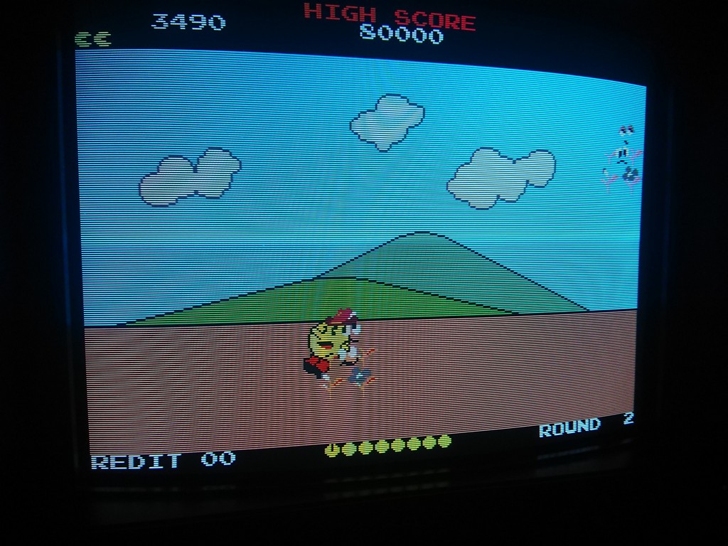
Looks like that corroded pin has broken contact somewhere. Anyway, replacing the RAM brought all the sound back to life and completed this repair.

Metro Cross repair log ( same hardware of Baraduke)

 General, PCB Repair Logs  Comments Off on Metro Cross repair log ( same hardware of Baraduke)
Mar 302020
 

The game at first didn’t boot due to the watchdog circuit being triggered.

There were 4 work srams by Toshiba and first one from left was faulty.

Unfortunately soon after , game started to reset again and the second sram from left failed.

The PCB had then all sprites in a single row and was missing the text on the upper and bottom area and soon after it losts also the BLUE component

Decided to start from the easy part and restored the missing colour.

Green and blue components are generated by the PROM @ 1N.

Signals were good so the fault was in the 74LS173@2P which had all output stuck at 0V

After changing the TTL I restored the blue component.

The missing text was due to the 74LS195@6L , while checking it I saw that the text reappeared but glitched

After changing it I finally had again the text


To restore the sprites I decided to concentrate on the \HSET signal on the sprite address generator circuit.

This signal comes from pin 22 of CUS35 and it was always stuck LOW. I took another CUS35 from a BaradukeĀ  board and the problem remained.

So I decided to look at the other side and checked two 74LS173@9N and 9P

I shorted for a brief moment the \Hset signal to 5V and the sprites were correctly drawn again and the signal was oscillating.

But I noticed that some sprites has some glitching on colours.

I decided to replace both of them

Board was 100% fixed


Of particular note is that all the faulty TTLs were by Texas Instruments ( not Fujitsu!) and of uncommon type.

It seems Namco had a stock of these ICs to be used on an hardware design šŸ˜‰

Please note also that CUS35 is 100% compatible with CUS48 from later Namco system 1 games.


Pacland repair log #5

 General, PCB Repair Logs  Comments Off on Pacland repair log #5
Mar 292020
 

Second Pacland pcb I got for repair is a Namco one.

It had some sprites wrongly selected by the game code

After checking on the schematics the sprite addressing I found this:


pin 16 of 74ls377@7KĀ  was stuck low thus selecting the wrong sprites on the sprites eproms

After changing it board was fixed:

Pacland repair log #4

 PCB Repair Logs  Comments Off on Pacland repair log #4
Mar 292020
 

Got two Pacland pcbs to be repaired from a friend.

Fist one is a Sidam Pacland which showed the following problem:


All the screen had shadowed colours going up and down vertically.

By expecience whith similar problems on different hardware I understood it was a Hblank problem.

The game didn’t shut off the screen at the borders so the monitor didn’t have anymore the black reference.

Looking at the schematics I found immediately a clear reference to the blanking circuit:


Compblank was oscillating, while COMPBLANK A and \COMPBLANK A were stuck.

Chaning the 74LS74@6M fixed completely the issue


Operation Wolf repair log #2

 PCB Repair Logs, Repair Logs  Comments Off on Operation Wolf repair log #2
Mar 272020
 

Got this board set from Paulcan69 to have a look at.
The faults reported were gun shots do not register & there was no sound.
I was told before hand that the gun issue seems to be a very common problem so I focused my attention on that first.
The input from the gun comes in from the sound PCB and passed straight down to the main PCB.
First I checked the signal from the gun was actually reaching where it should do

I confirmed that on a trigger press in game that the signal reaches pin 3 of the 74F74 at IC26 and also that pin 5 output latched.
Using the scope I could also confirm the operation of the 74LS75 at IC38.

The current XY screen draw position is tracked by a set of 74LS161 counters and fed into 74LS373 transparent latches.

When the trigger is pressed the the 74LS373’s are latched and the current XY values are sent to 3 x 74LS257 data selectors.

These selectors are read by the main CPU from address $3A0000 – $3A0001.
Using the scope syncing on pin 15 of the 74LS257’s I confirmed that some of the outputs on these were always logic HIGH.
I ended up replacing IC67 & IC83 which fixed the gun problem.

Next was the sound issue.
This one had no sound at all.
All the signals looked OK from the CPU side but nothing was ever being asked to play a sound.
Given the fact that the board uses the Sony brand RAM I just went right ahead and removed it as they have been very unreliable in recent times.
It failed in an out of circuit test using my programmer

Now the music was back but the samples did not.
I already had a pretty good grasp on how the sound worked from my previous repair so started checking the same areas as before but didn’t really find anything but then I spotted this

This is part of the feedback circuit for the op-amp. Replacing this gave me some samples back but they cut out before they finished playing and some didn’t play at all

I knew exactly where to look for this and quickly found the 74LS688 at location IC41 with its output stuck LOW.

I removed and tested which obviously failed

I initially thought I would have to put this repair on hold as I needed to order some 74LS688’s but turned out I had to wait less than 24hrs for Farnell to deliver.
With the new chip fitted I had my sounds playing for the right duration but all the samples on the A channel were still missing altogether.
Using the scope I traced the sound to the output of the M5M5205 ADPCM Speech Synthesis LSI at IC50 (schematics incorrectly refer to it as IC51)

I could see the signal going into the op-amp but nothing was coming out so I replaced it.

I now had an output from the op-amp but still no sound. Tracing this through on the PCB I came across another damaged capacitor (no idea how I missed this one as well)

Replacing this brought all the sound back and that’s another one complete.

 Posted by at 8:01 pm