Hello everyone, this time I have a SNK Neo-Geo MVS game cartridge on my desk. It has glitches with some of the graphics.
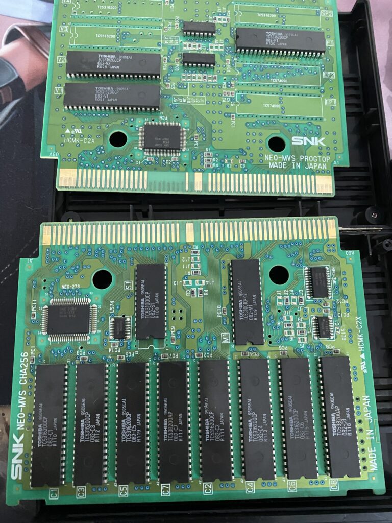
MVS cartridges consist of 2 boards – the PROG board and the CHA Board.
This particular PROG Board holds 16-bit P ROMs and V ROMs.
P ROMs are Program ROMs. Some other Neo-Geo games use 8-bit parts instead for the P ROMs labeled either SP1/2 or EP1/2.
V ROMs are audio ROMs which holds ADPCM audio samples.
Since this game boots up and runs, and the sound is perfect, we don’t need to examine the PROG board at the moment.
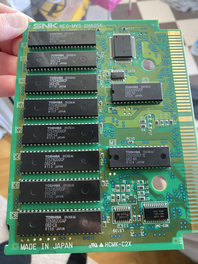
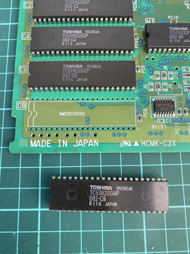
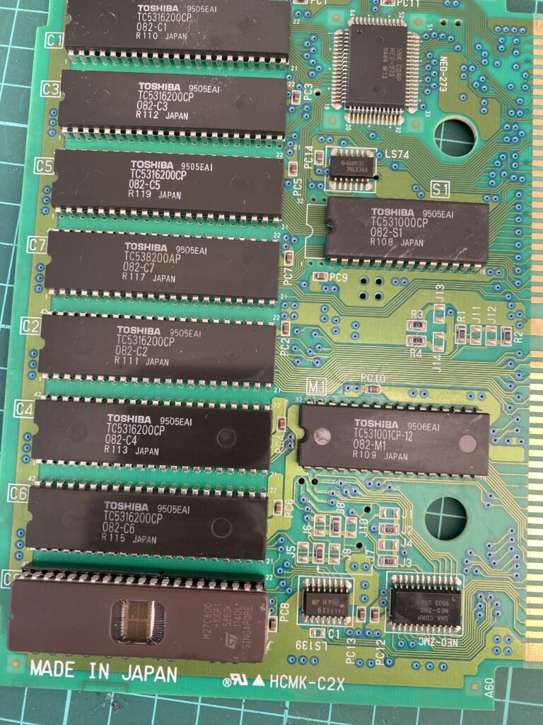
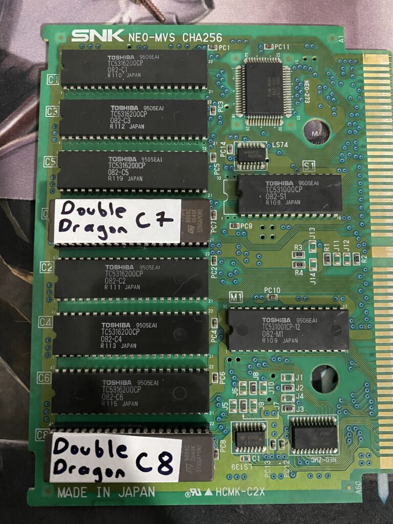
Let’s take a look at CHA board. CHA Boards hold C ROMs, an S ROMs and a M ROM.
M ROM is a 8-bit ROM containing the Z80 Sound CPU program and data. Without it, you don’t get any sound.
S ROMs are Graphics ROMs containing tiles for the “fix” layer. The fix layer is a non-scrollable, tile-based layer with transparency which has the highest priority on the display (it always overlaps sprites). It is most often used to display text or HUDs like scores and health bars.
And finally we have C ROMs. C ROMs are 16 bit sprite graphics ROMs organized in pairs, each containing half of the bitplanes for sprite tiles.
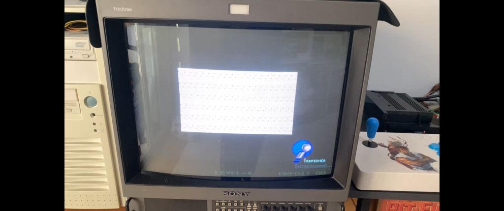
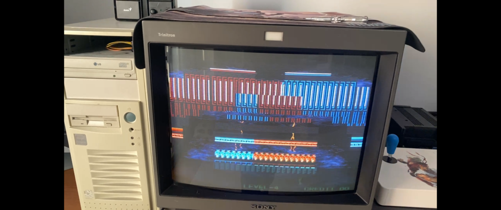
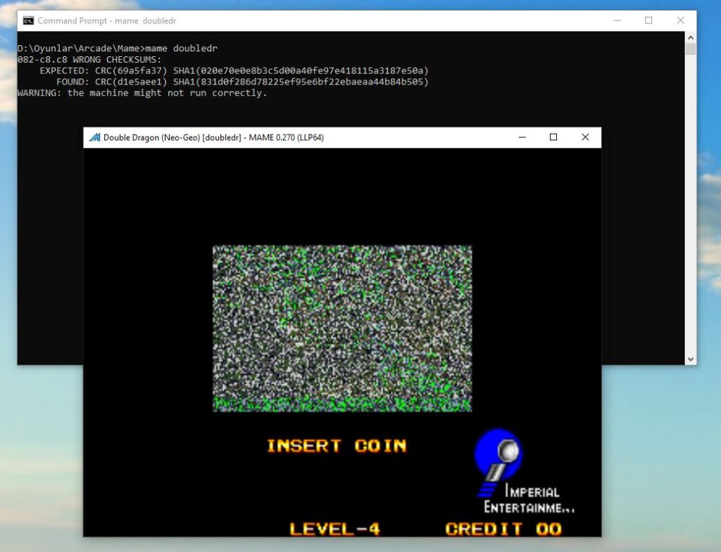
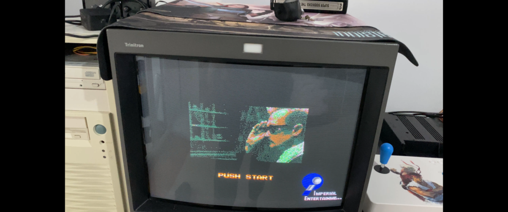
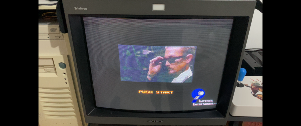
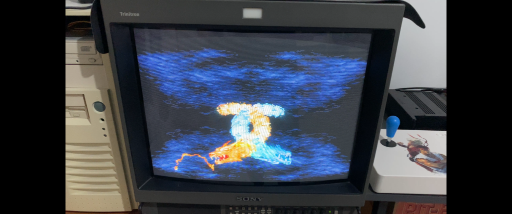
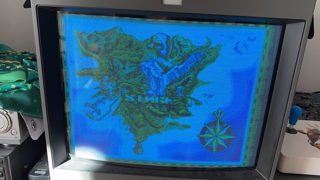
Let’s see the fault with this particular cart before proceeding further. This white square is supposed to display a video:
Where’s the background???
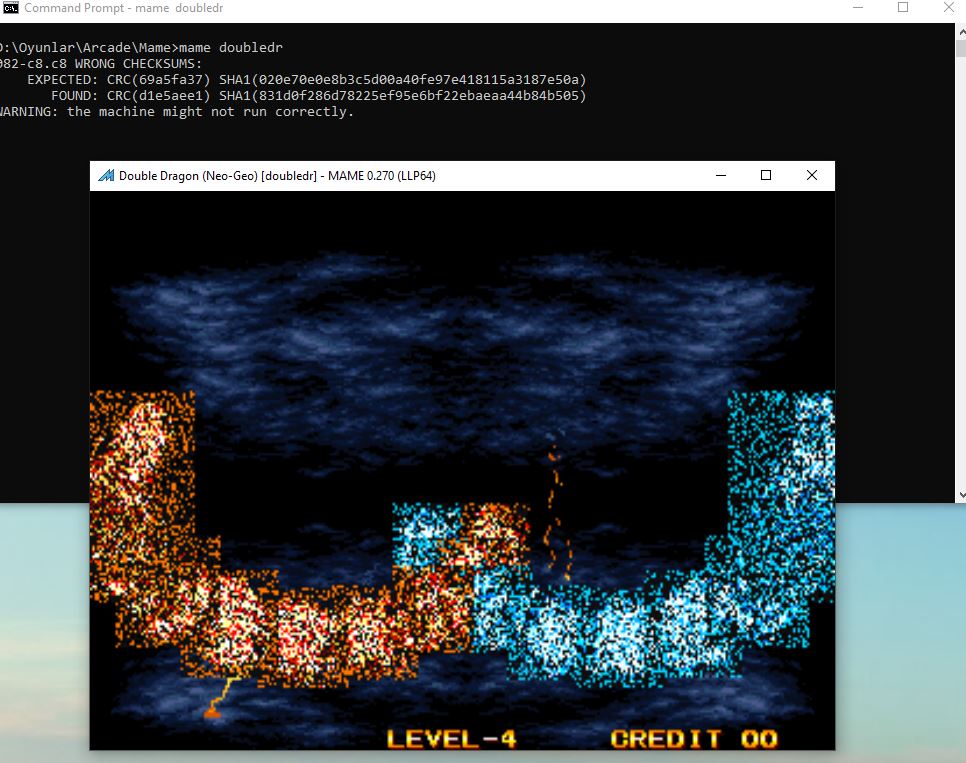
There’s supposed to be two Dragons showing here instead of glitches.
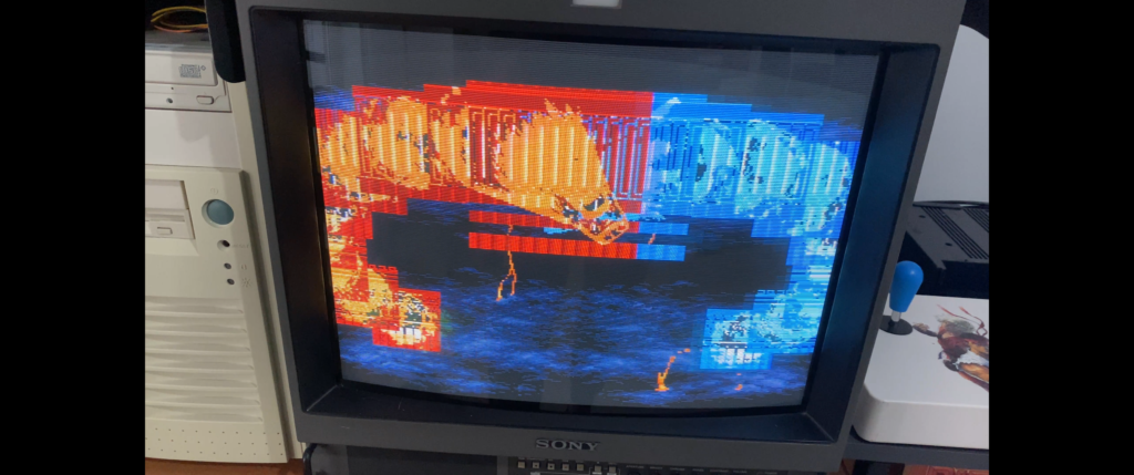
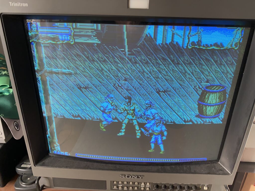
Also you can see a video of the graphics corruption here:
Okay, since the graphics issues are with sprite tiles, we know the problem is with the CHA board, and we know that there’s something wrong with the C ROMs. But which ones?
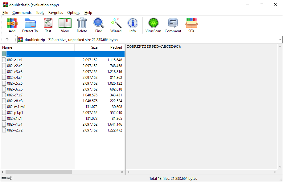
For this situation, let’s consult the MAME ROMs. MAME’s dump of this game is “doubledr.zip”. Here are the contents – there’s one file for each ROM chip on both boards.
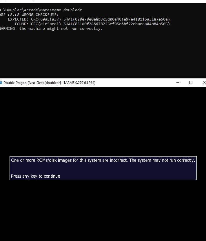
What I will do now is simulate the same error I’m seeing with my physical cart on MAME by corrupting each C ROM file one by one.
Normally, MAME does a hash check on each file when booting up a game – if the hashes don’t match for a file, it won’t start the game. But if you launch MAME from a command prompt, it only warns you and it will start the game.
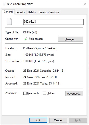
I’ll start with corrupting the C8 ROM since it is 1MB in size, and thus equivalent to a 27C800 EPROM (of which I have plenty).
That’s looks like it – when MAME runs with a corrupt C8 then the same sprites look glitched as on my cart. The glitches look different glitches but the same sprites are affected.
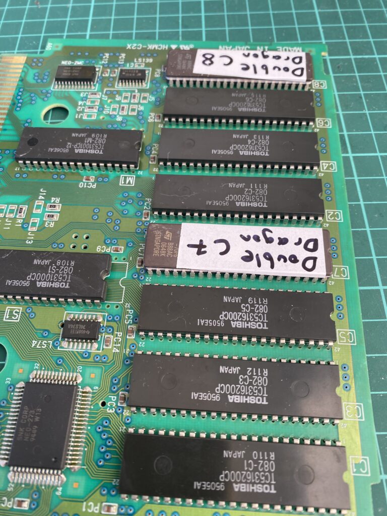
Let’s desolder the C8 ROM from the board:
The MAME file for this part is 1MB in size. As mentioned above, the EPROM equivalent is a 27C800. Be careful when replacing a mask ROM part with an EPROM part – don’t always do this by size, because some ROMs like M1/S1 use different pinouts.
Here is the CHA board with a socket and programmed 27C800 installed:
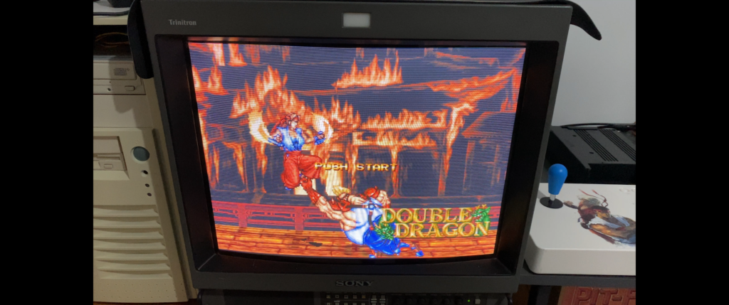
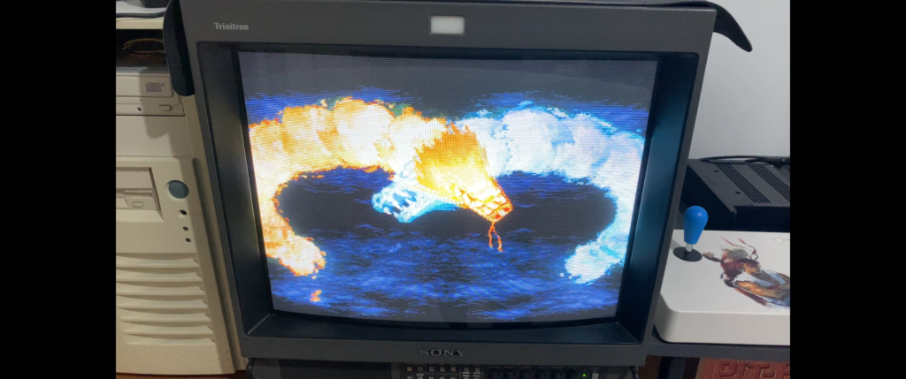
Time to power up and give it a shot!
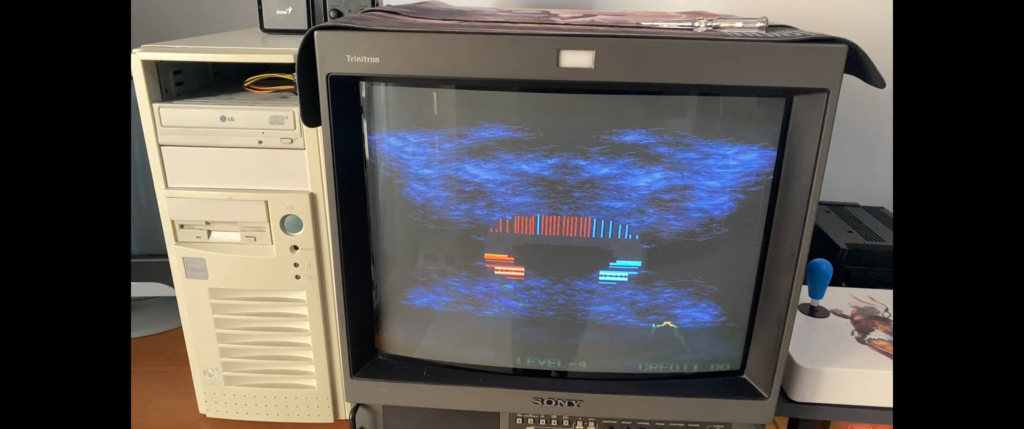
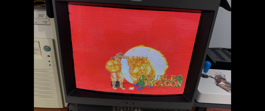
Well, the graphics are looking better than before, but they’re still bad. Here’s the video:
Next, I simulate a corrupt C7 ROM in MAME in the same manner and see that the same sprites glitch. So I go ahead and change out the C7 mask ROM for a 27C800 EPROM on the board too:
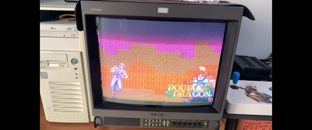
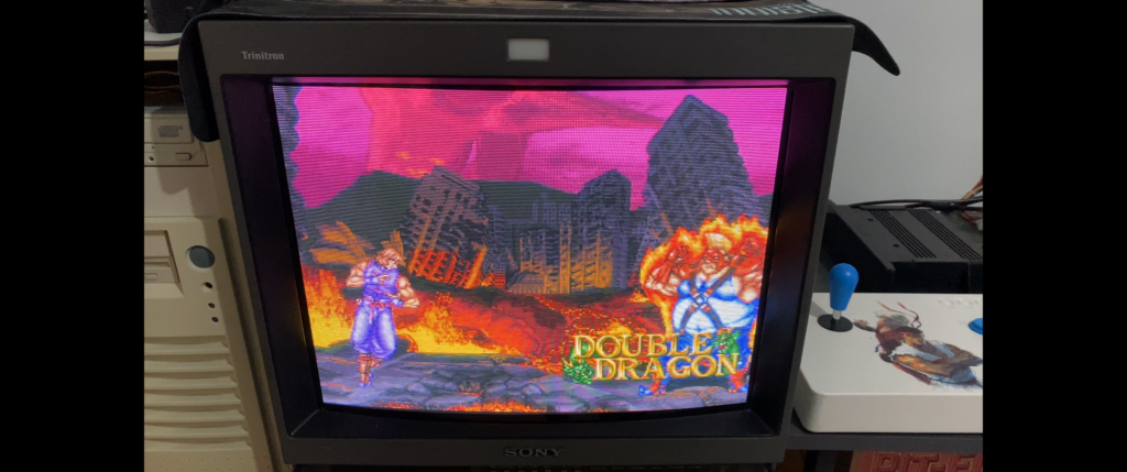
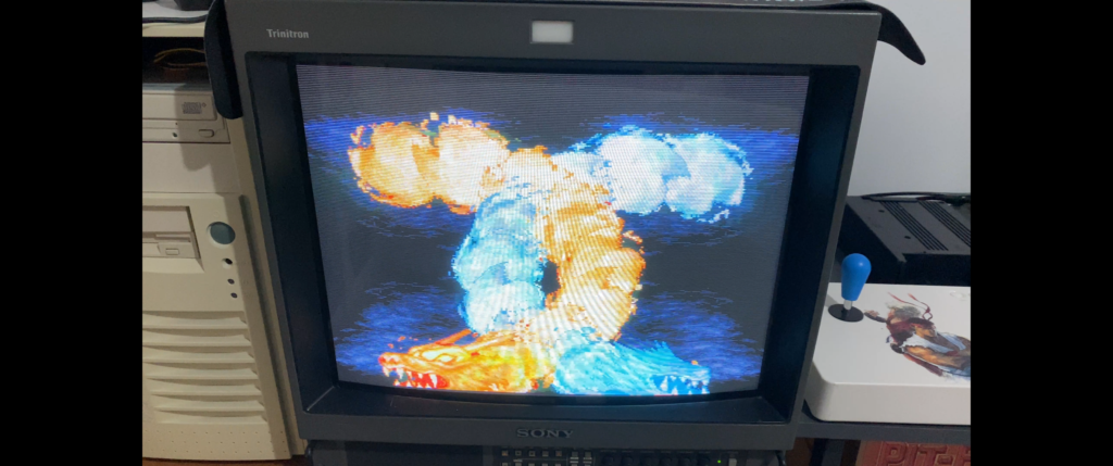
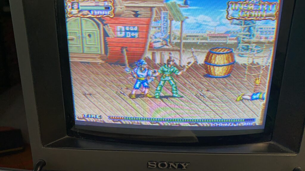
Now this is the result:
Everything fixed! Here’s the video:
It turns out that you cannot close up the cartridge shell when using sockets. Therefore, I desolder the sockets out and solder in the replacement EPROMs without sockets.
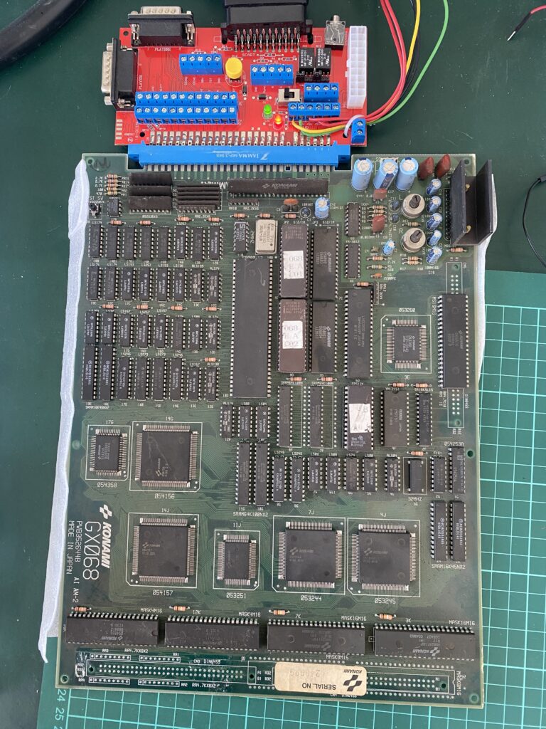
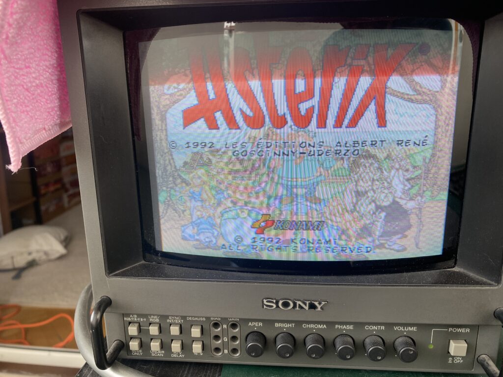
Hello everyone, this time I have a Konami Asterix board that I got from the Arcade Museum forums. I bought it as non-working “error with 2 chips” at an affordable price.
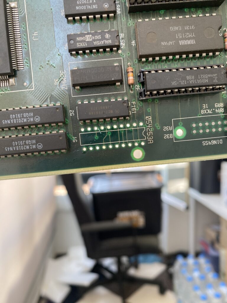
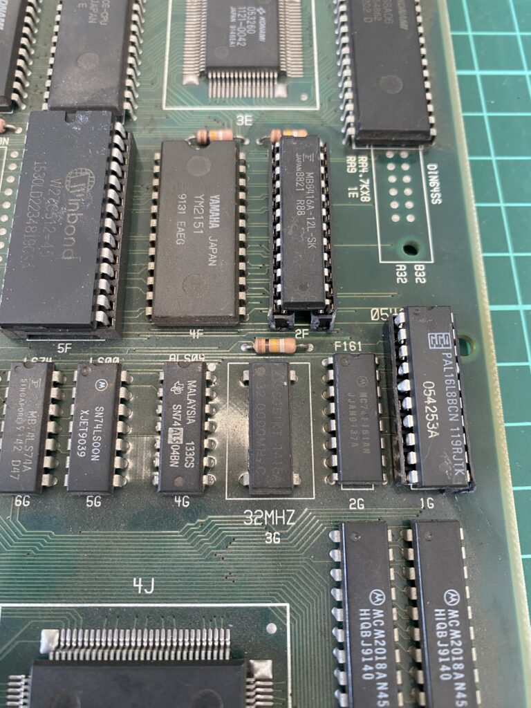
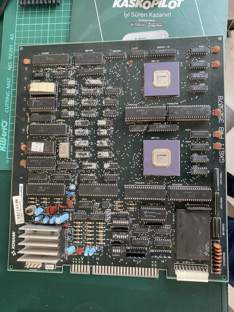
This is the board:
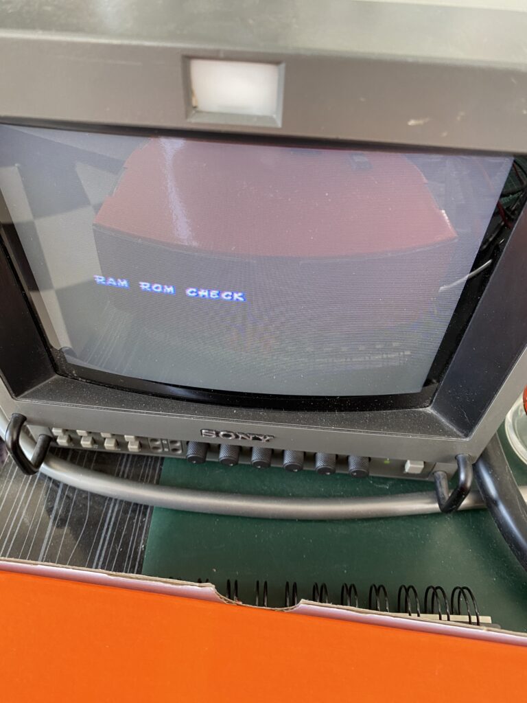
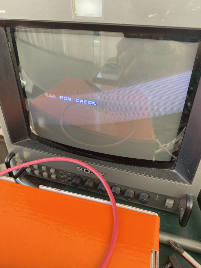
I immediately attached it to my JAMMA Test Rig and powered it up.
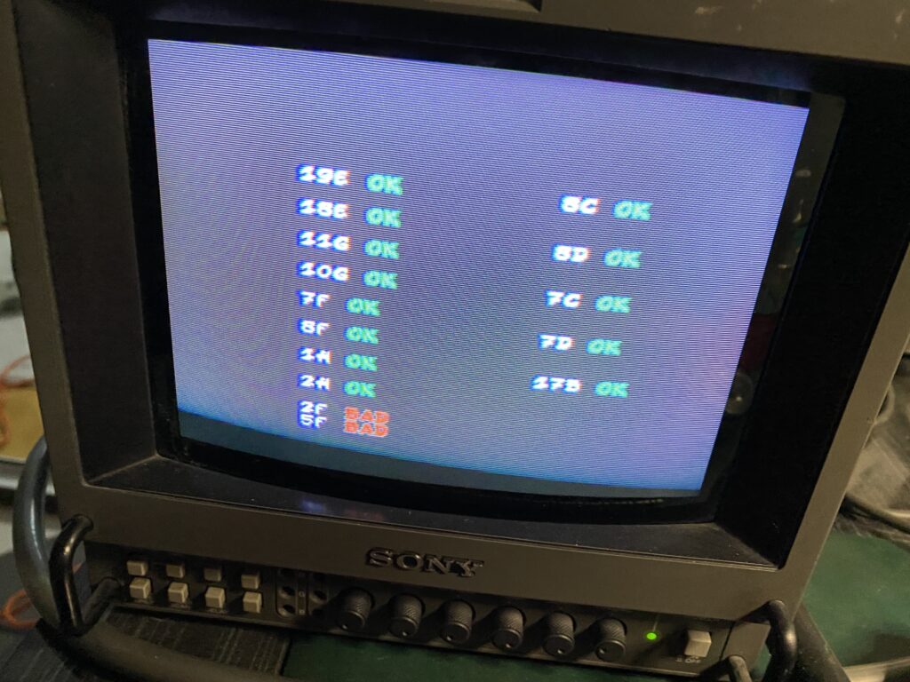
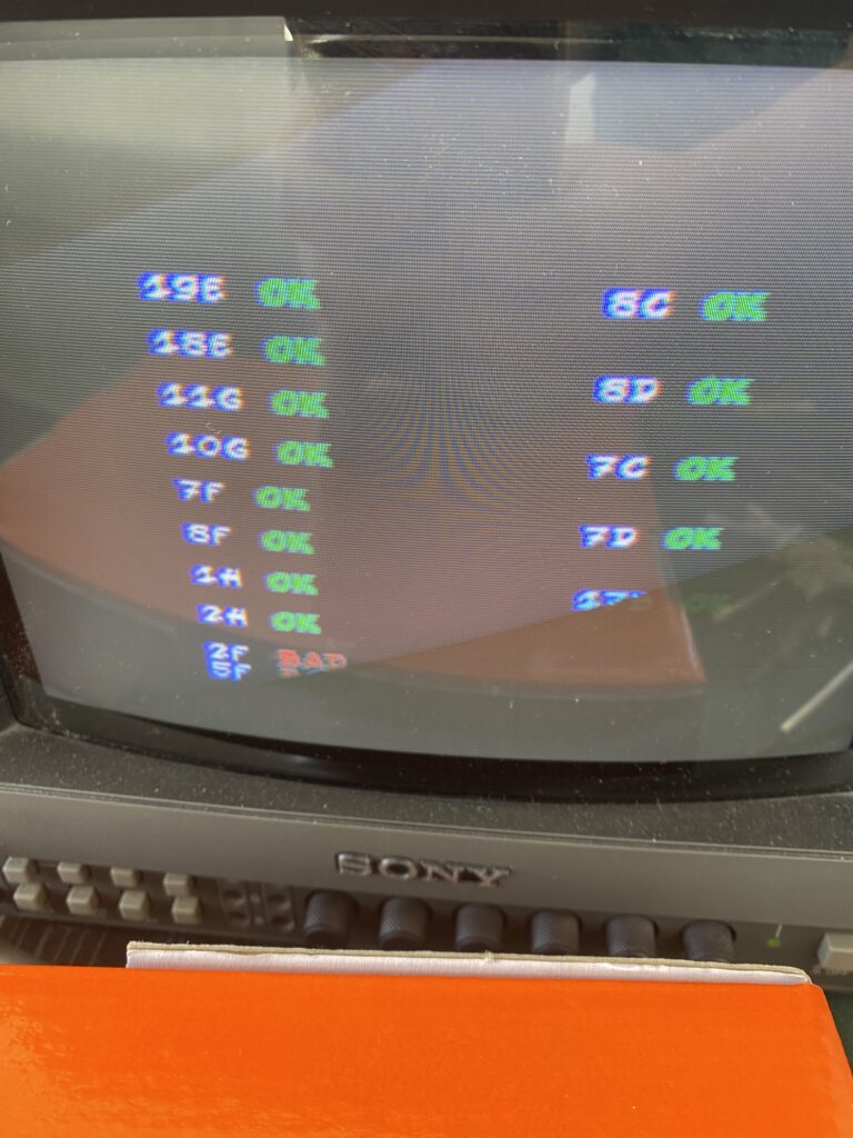
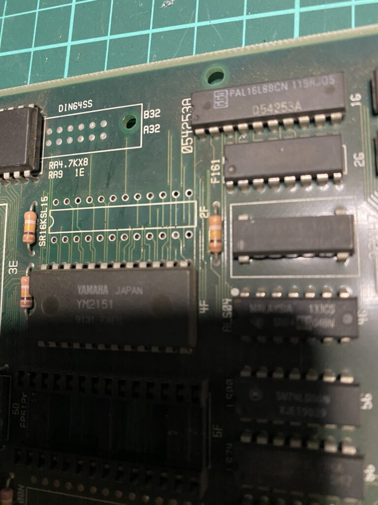
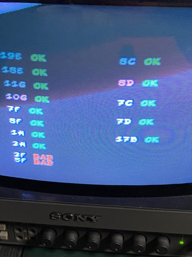
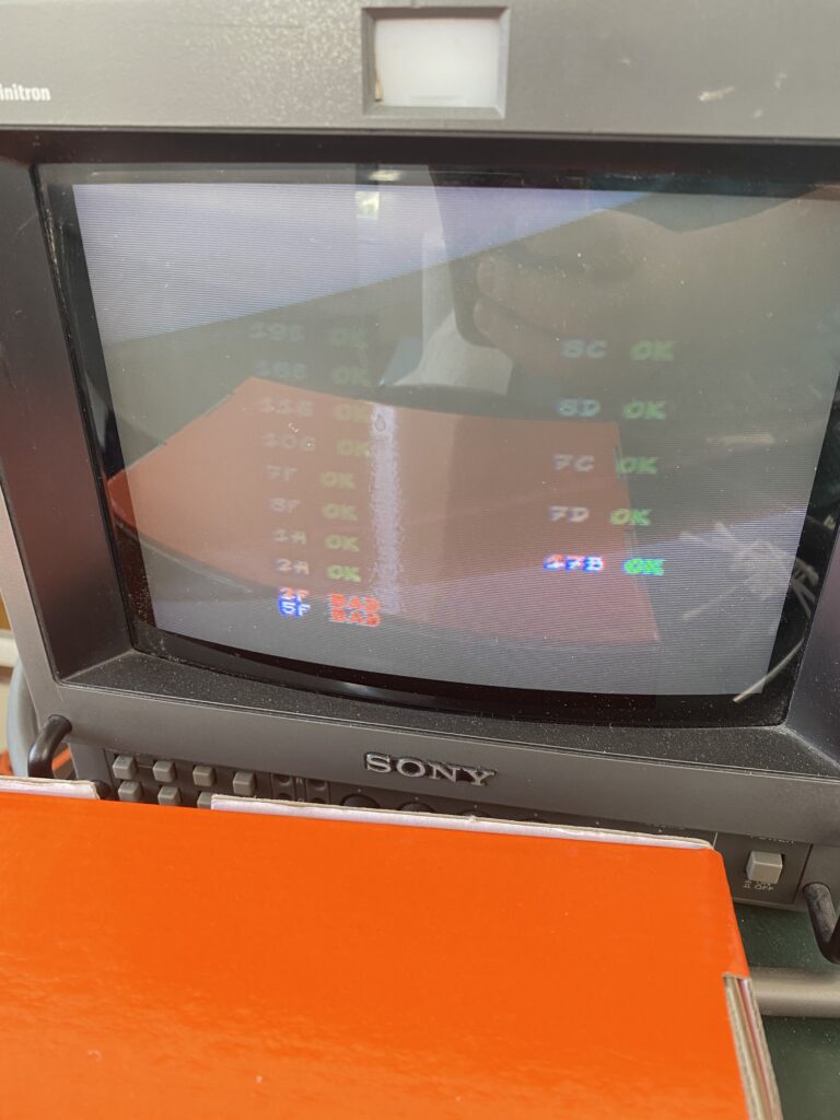
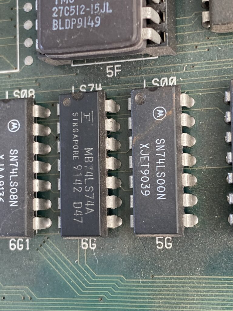
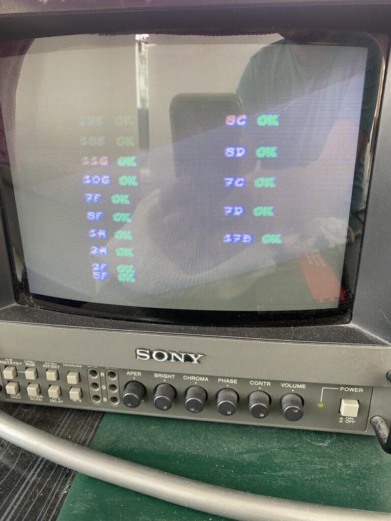
Indeed, we see 2 defective chips on the board’s ROM Check screen – 2F and 5F.
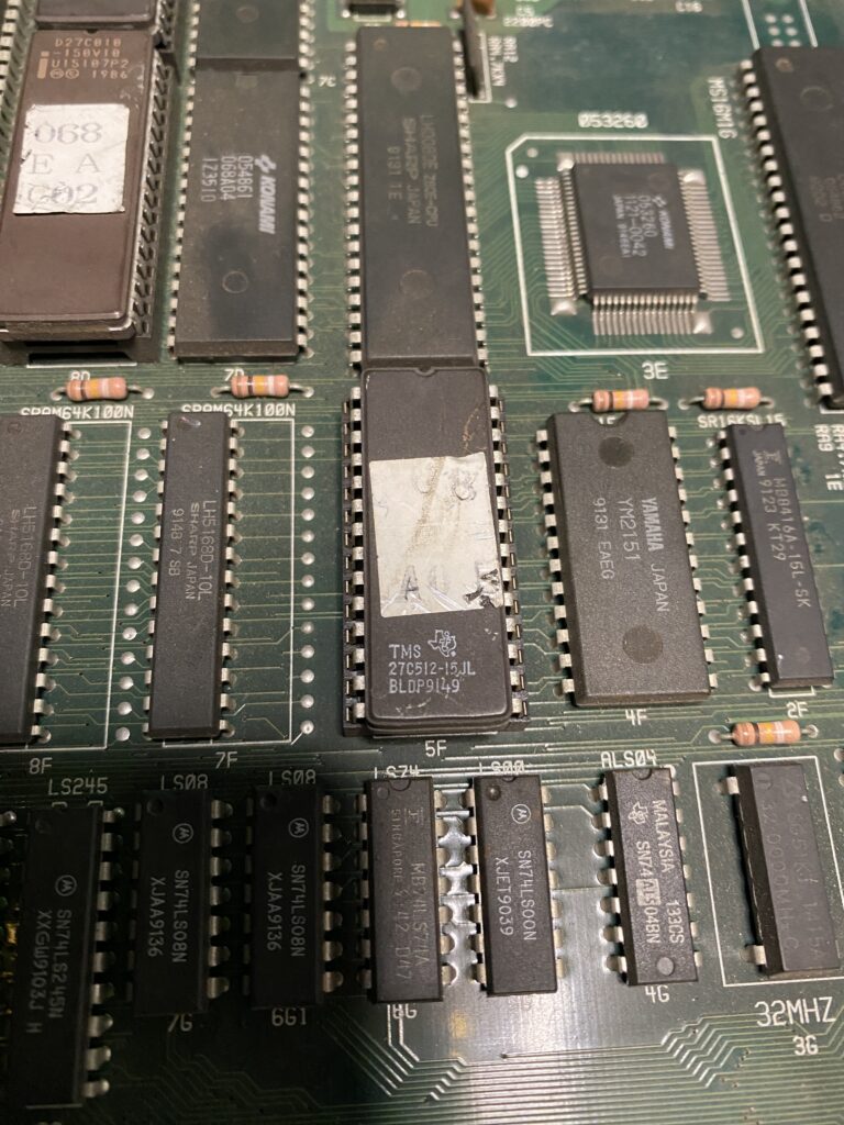
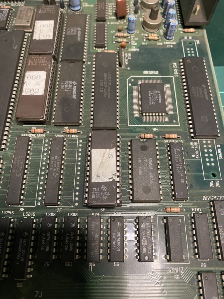
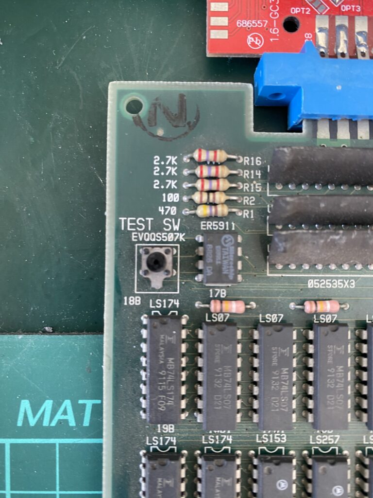
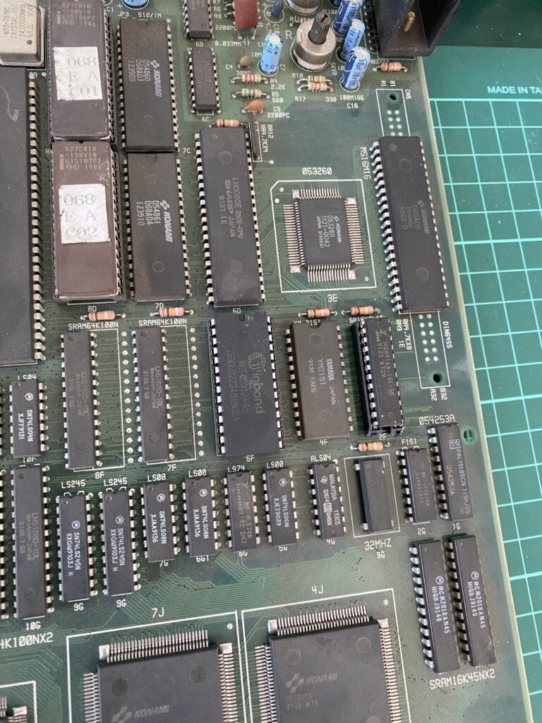
When examining the board, we see that 2F is a RAM chip while 5F is a ROM chip.
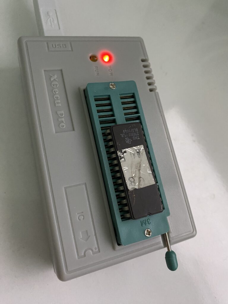
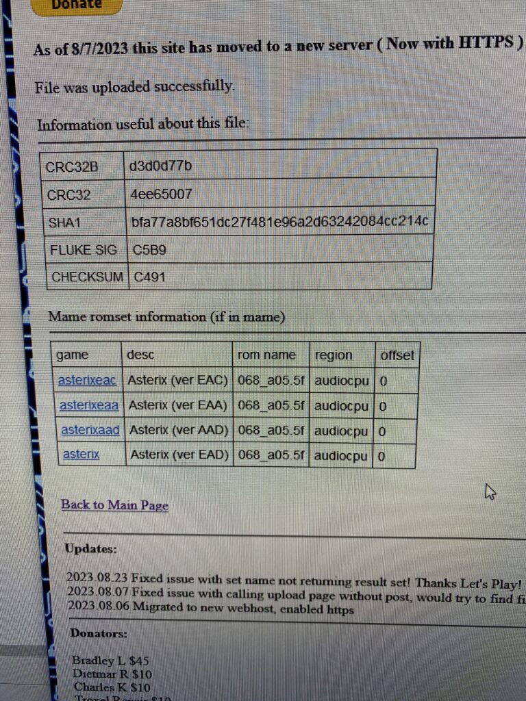
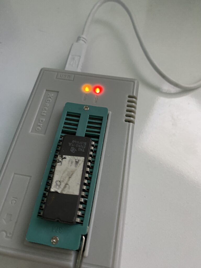
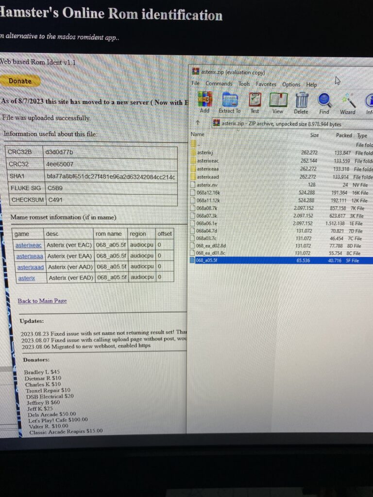
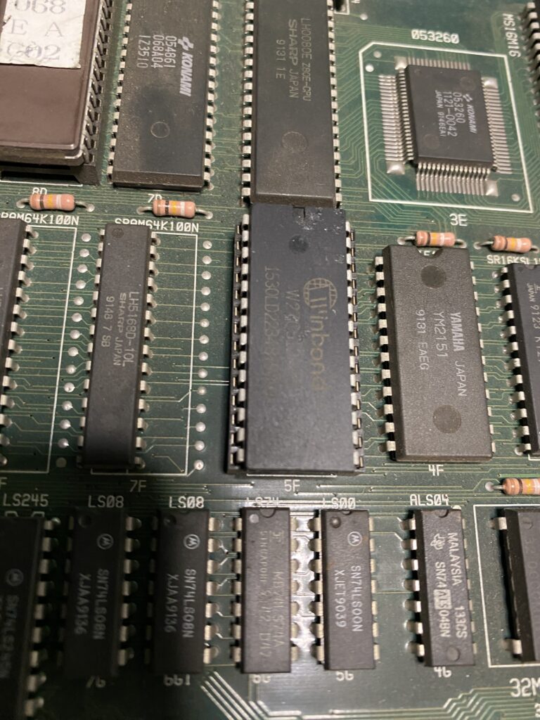
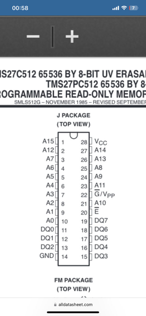
The 5F EPROM (TMS27C512) is already socketed, so let’s dump it and compare it with MAME via the ROMIdent site.
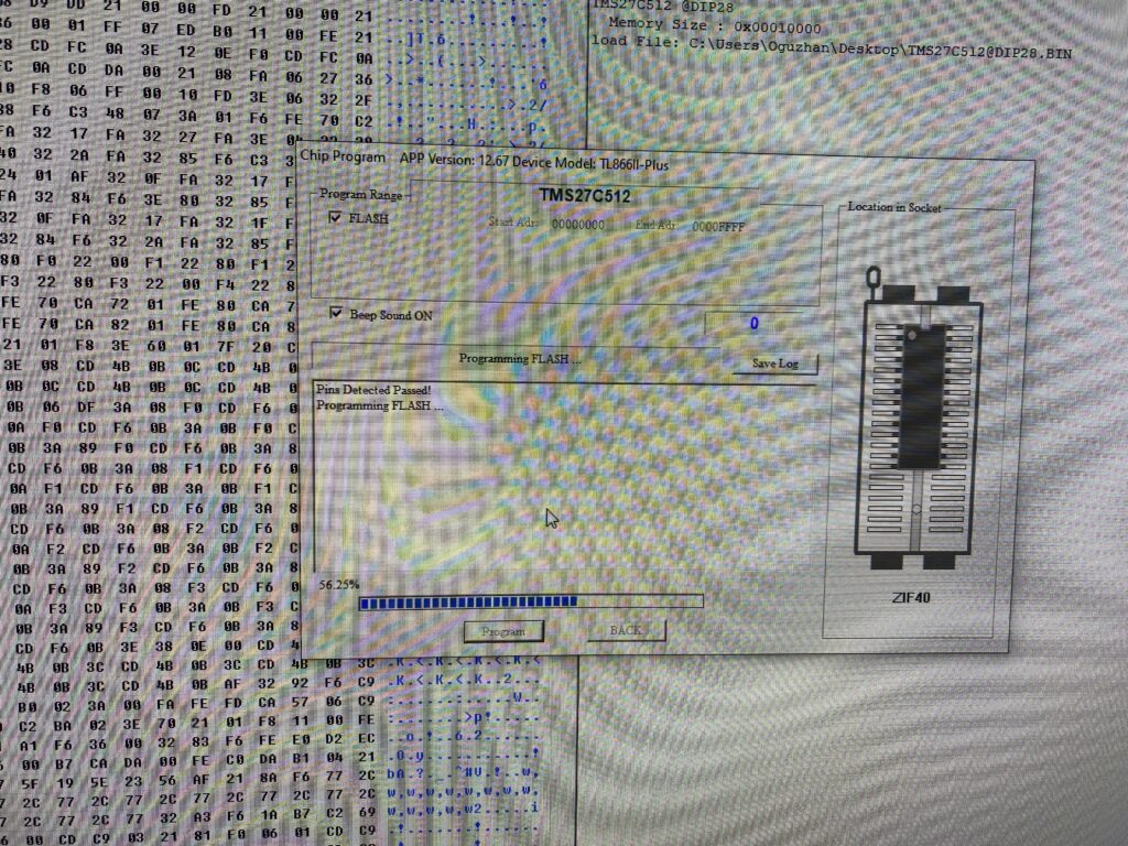
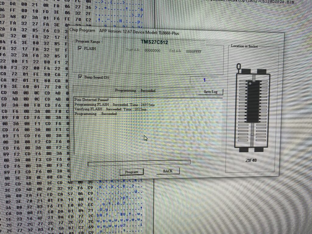
The ROM looks fine and matches what it should be. For good measure though, I’ll rewrite the dump back to the EPROM.
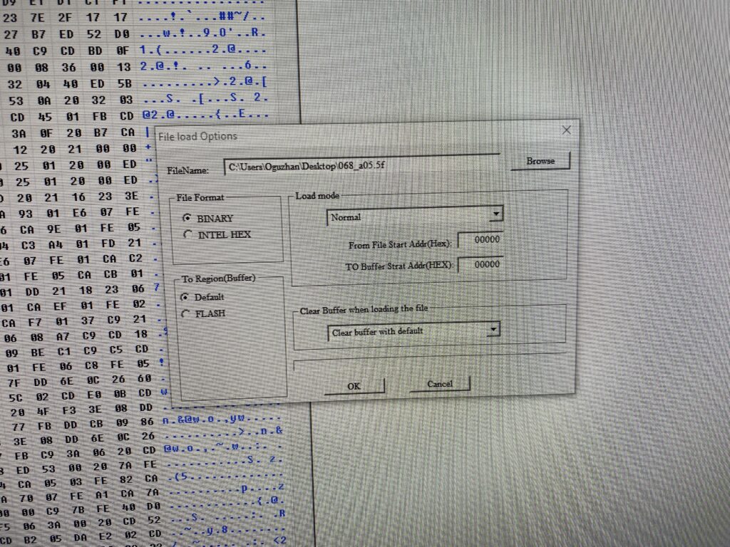
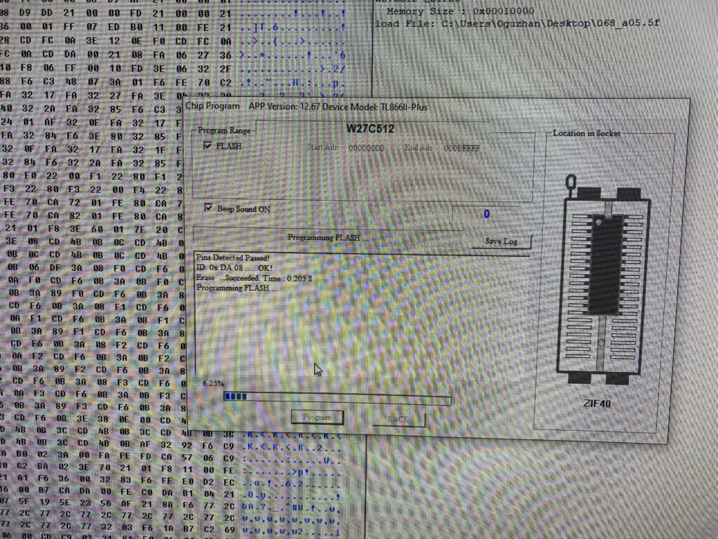
Then, while I’m at it, I’ll write the MAME equivalent dump file 068_a05.5f to another EPROM (W27C512) that I’m sure is good, so that we can try both.
First, I’ll put the old ROM back in and try it out.
Let me give you some information if you try a similar experiment. With some Konami boards, if you change ROM chips, the system might not detect it. For example, when switching from a 2P ROM to 4P ROM, or switching to a different language ROM.
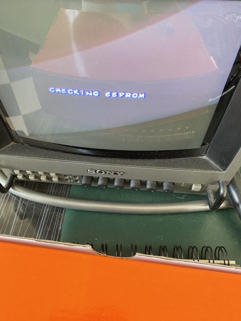
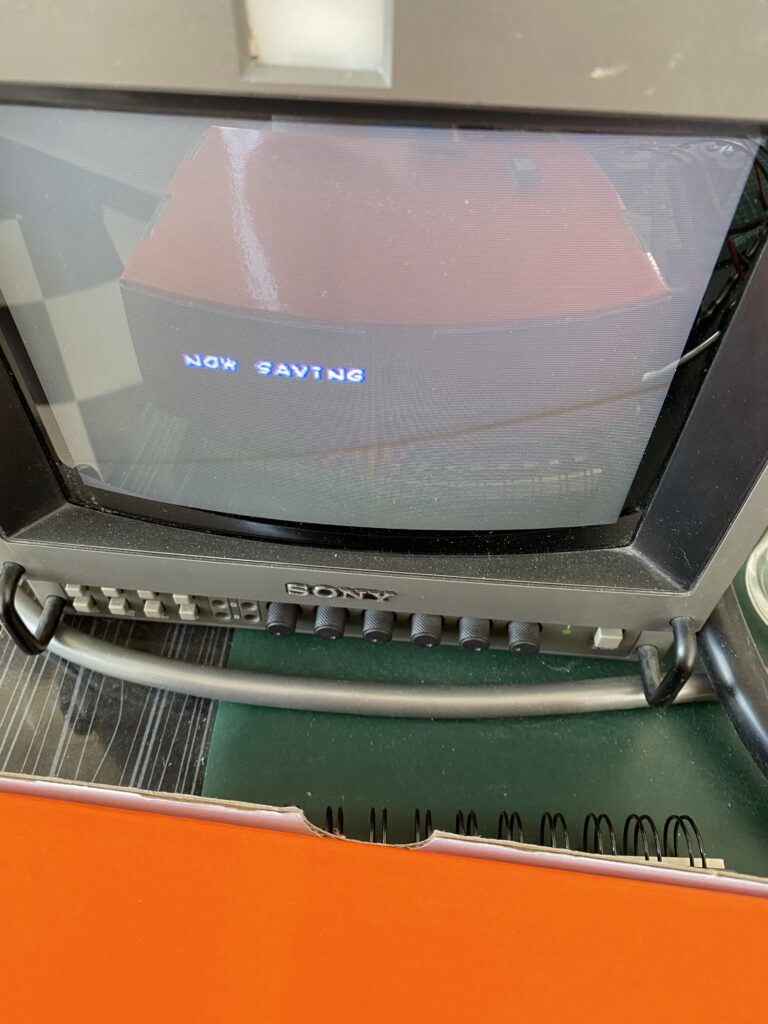
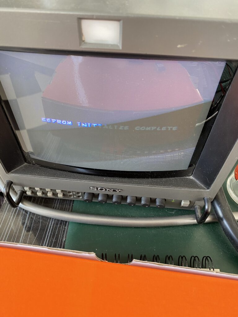
If this occurs, hold down the TEST SW button while powering on the board. You should see an EEPROM Initialization message.
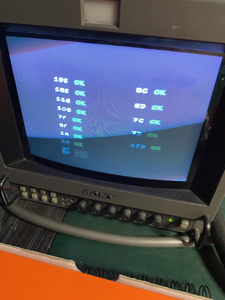
After the EEPROM reinitializes, it goes into the normal boot routine. Let’s see if 5F is fixed.
Not yet! Let’s try the new EPROM I wrote in case the old part is faulty.
It’s still not fixed. For now, let’s leave all this aside and deal with the RAM. Maybe problematic RAM is also causing problems accessing the ROM.
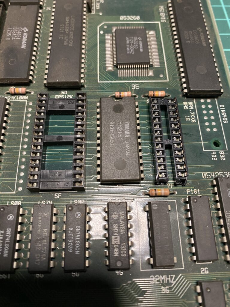
I carefully remove the old RAM by desoldering it from the board.
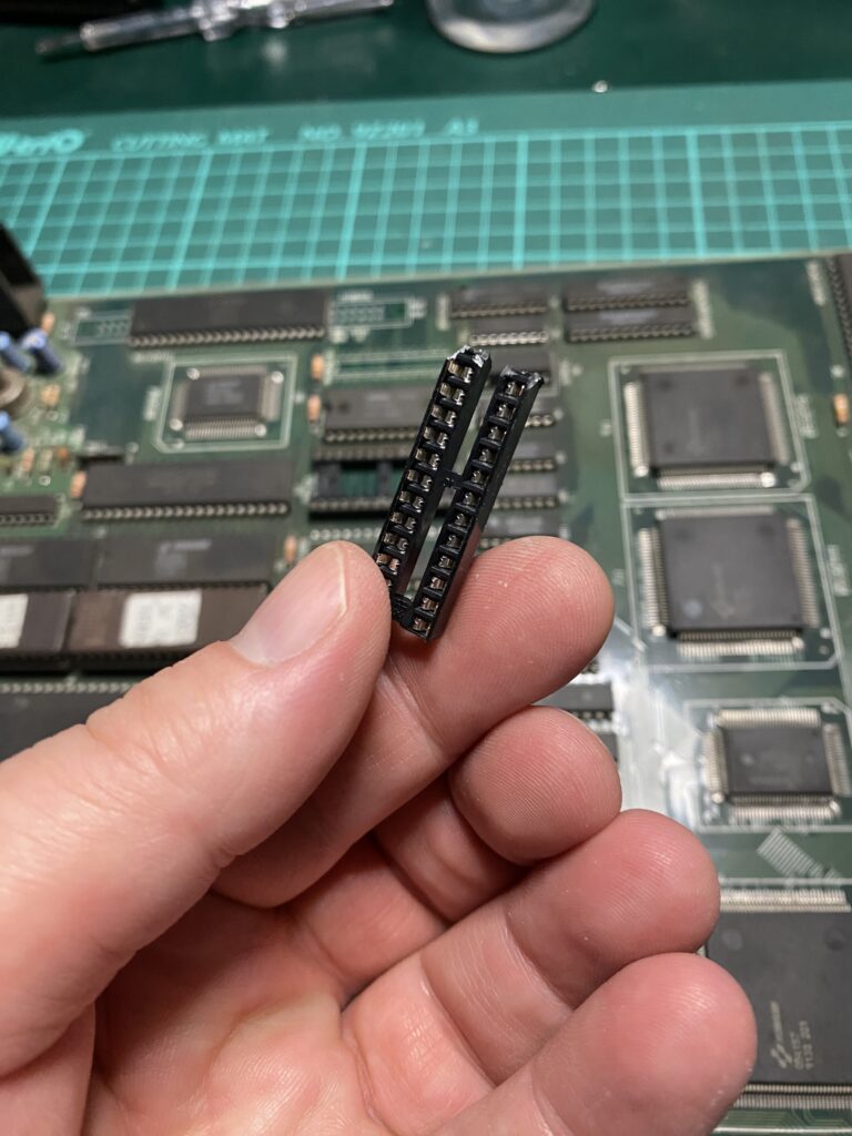
I’m out of suitable sockets for that pinout, so I cut down a large socket. It’s not fantastic but it does work!
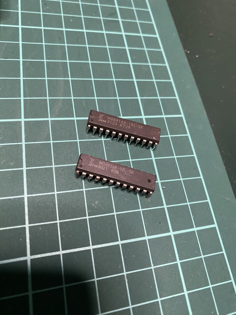
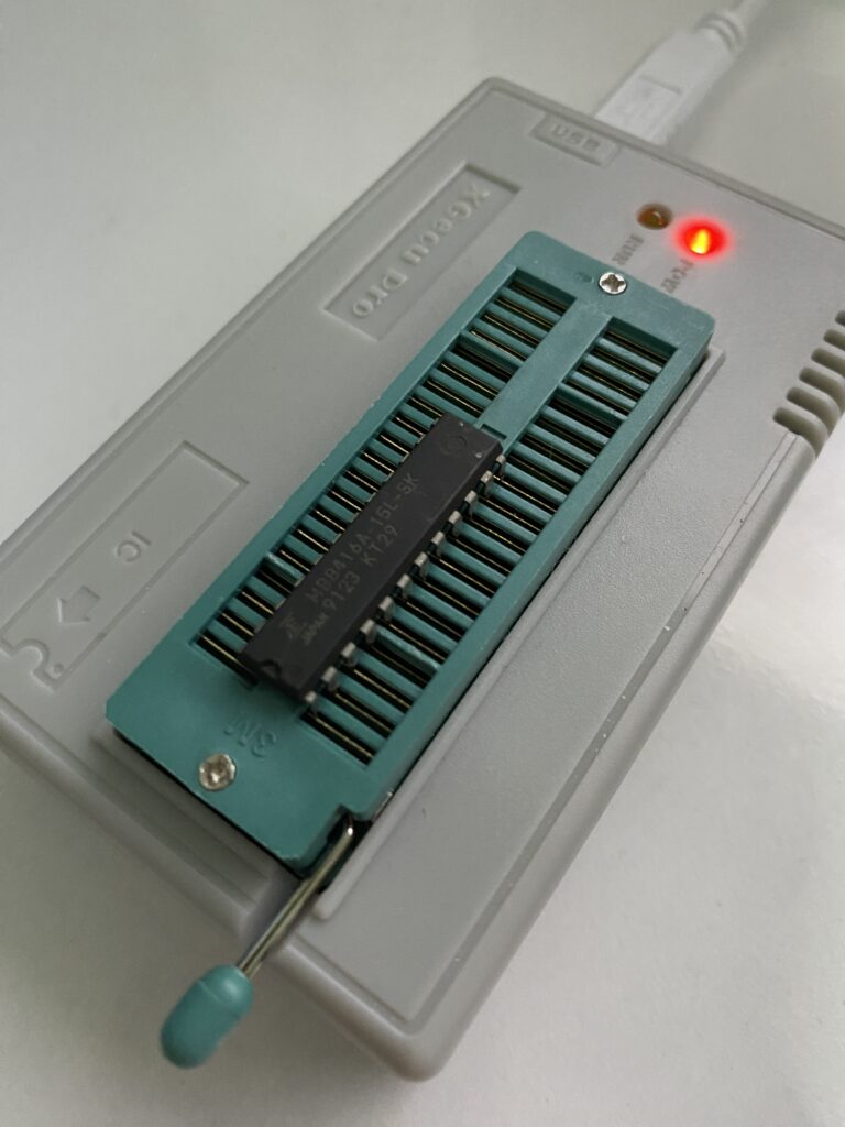
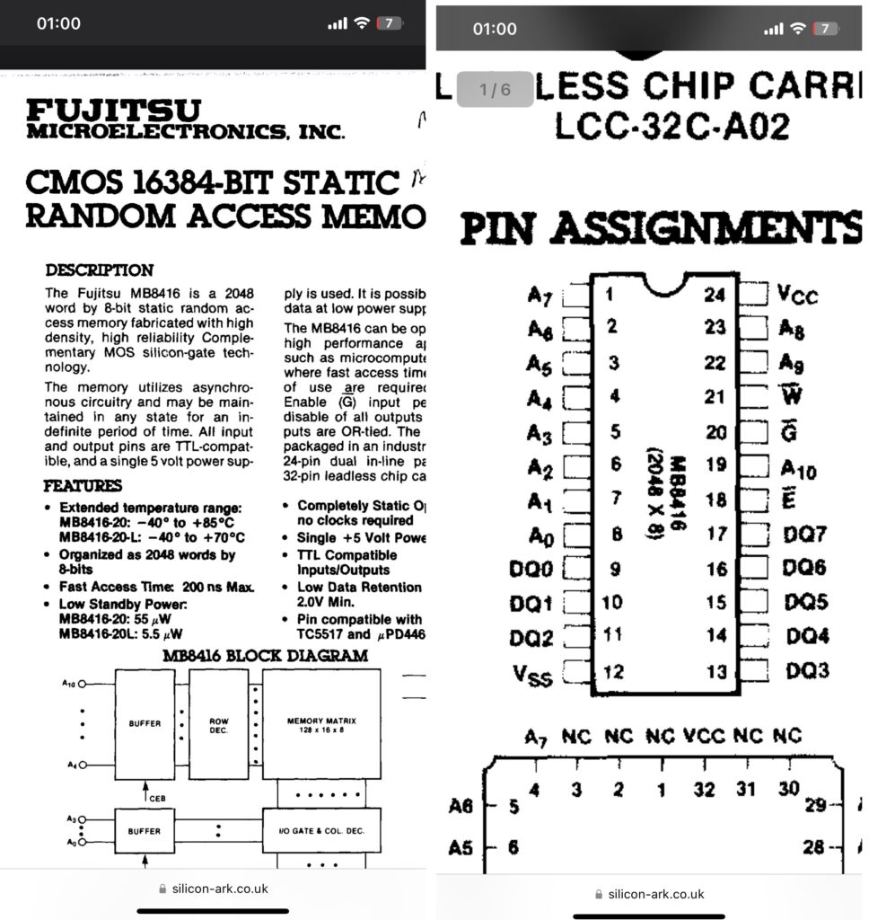
The part number of the RAM that came out of the board is MB8416A-15L-SK. I have a similar part that I can put in its place – MB8416A-12L-SK. The 12 means 12ns, i.e. shorter access time, i.e. faster RAM.
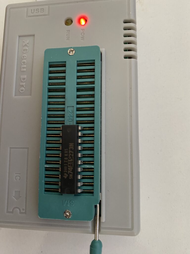
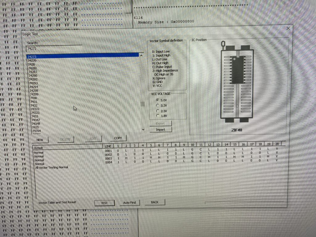
First, lets test the old RAM out of circuit with my EPROM programmer.
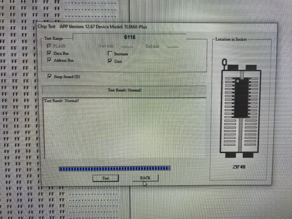
This RAM is a 6116 series equivalent. There are various cross reference sites to see equivalents. Or you can compare two datasheets and look; if you do this, pay attention to both the pinout and memory layout.
Test Result: Normal. The only time I regret that something is intact is when I’m repairing something and I suspect that the component is faulty. I wish it was faulty so I could just replace it and have it work!
Anyway, let’s install the new RAM into the socket and boot up the game board. Sometimes out of circuit test results can be inconsistent…
Hmmm, the 2F and 5F chips are still marked BAD so things are complicated. Apparently neither the ROM or the RAM is the problem. But somehow these two can’t be accessed correctly by the CPU. When examining the board for physical damage, I didn’t see any broken wires on the board. I didn’t see any cold solder.
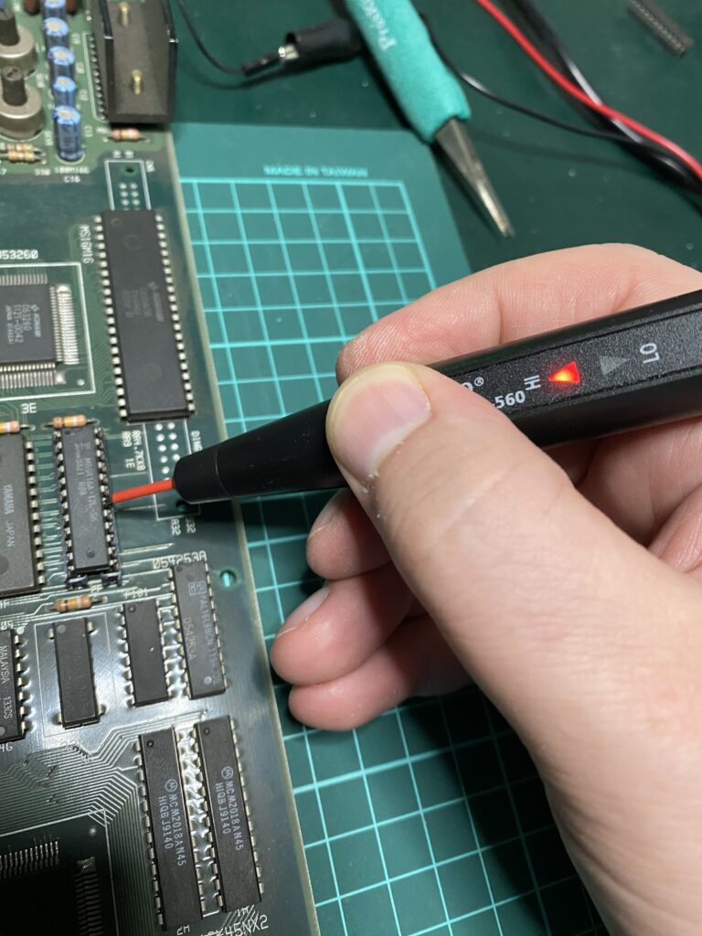
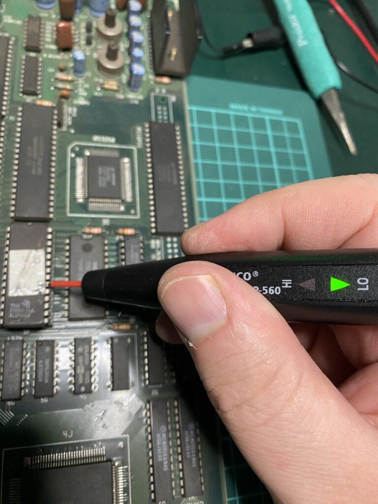
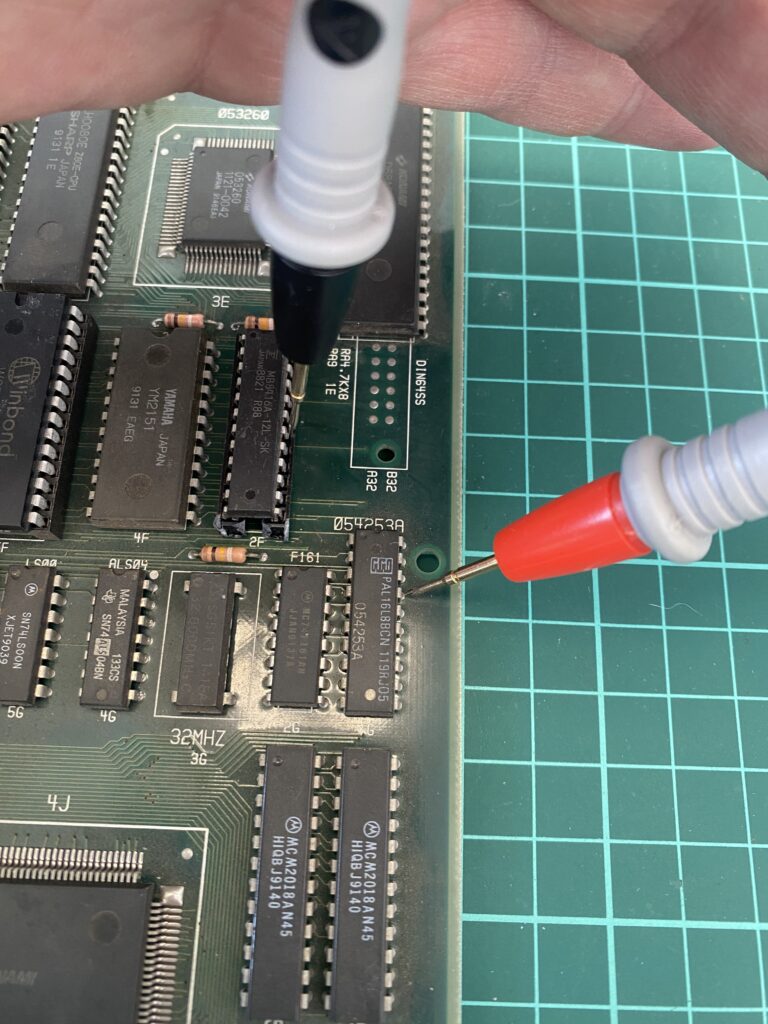
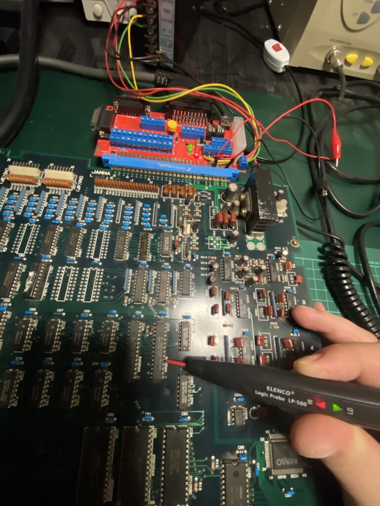
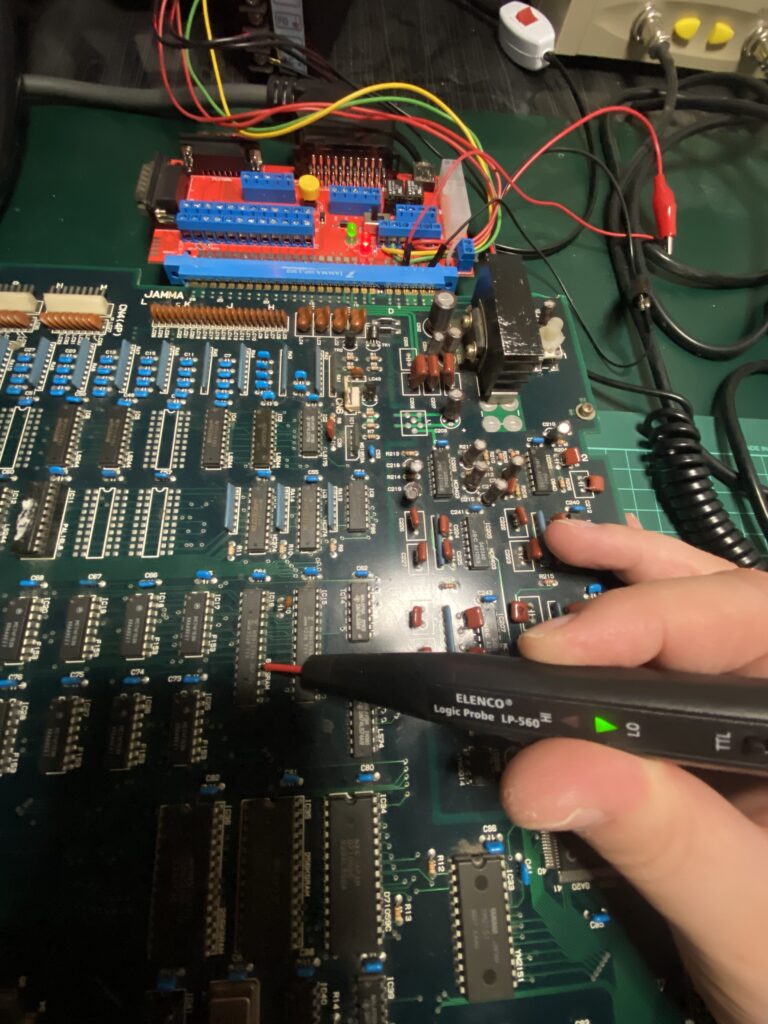
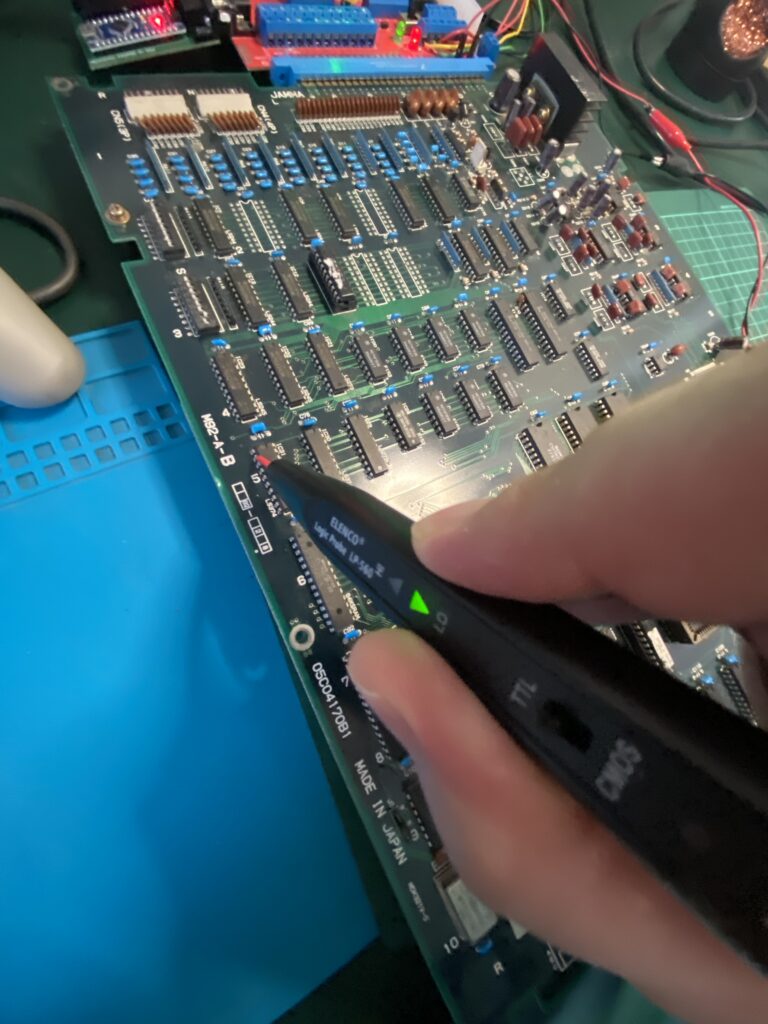
Let’s keep digging. At this stage of the repair, I take out my Logic Probe and start checking signals.
I see a High (No Pulse) signal on the 18th pin of the RAM. This is the Chip Enable pin. The datasheet shows a line over the label for this pin, showing that its Active Low. Thus, the RAM is not being enabled.
When I check the ROM, I see a LOW signal (No Pulse) on the Pin 20. This pin is also the Chip Enable pin for the ROM. Just like the RAM, the pin is labeled Active Low on the datasheet so the ROM is being enabled.
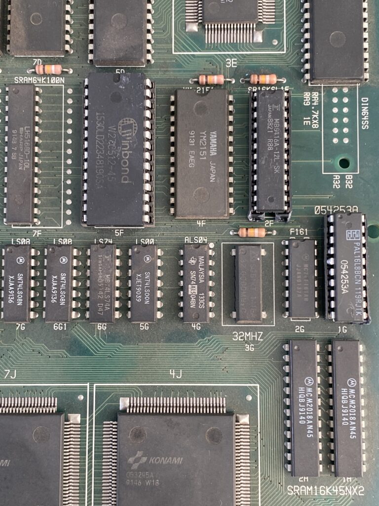
When I measure with a multimeter set to Continuity Test where the Chip Enable line of the RAM goes, I see that it goes to a PAL chip.
PALs are custom chips. If this PAL is faulty and has no dump, the only solution is to source a PAL from a donor board. If it has a dump (this one does), write the dump to a compatible GAL chip and use it. [Editor Note: The PLD Archive website is an excellent source for PAL dumps.]
I don’t have a GAL but I have a better option – a working Asterix board! Having a working board to compare against is very useful when working on boards without schematics like Asterix.
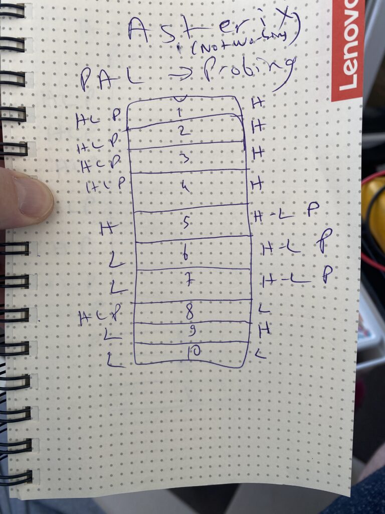
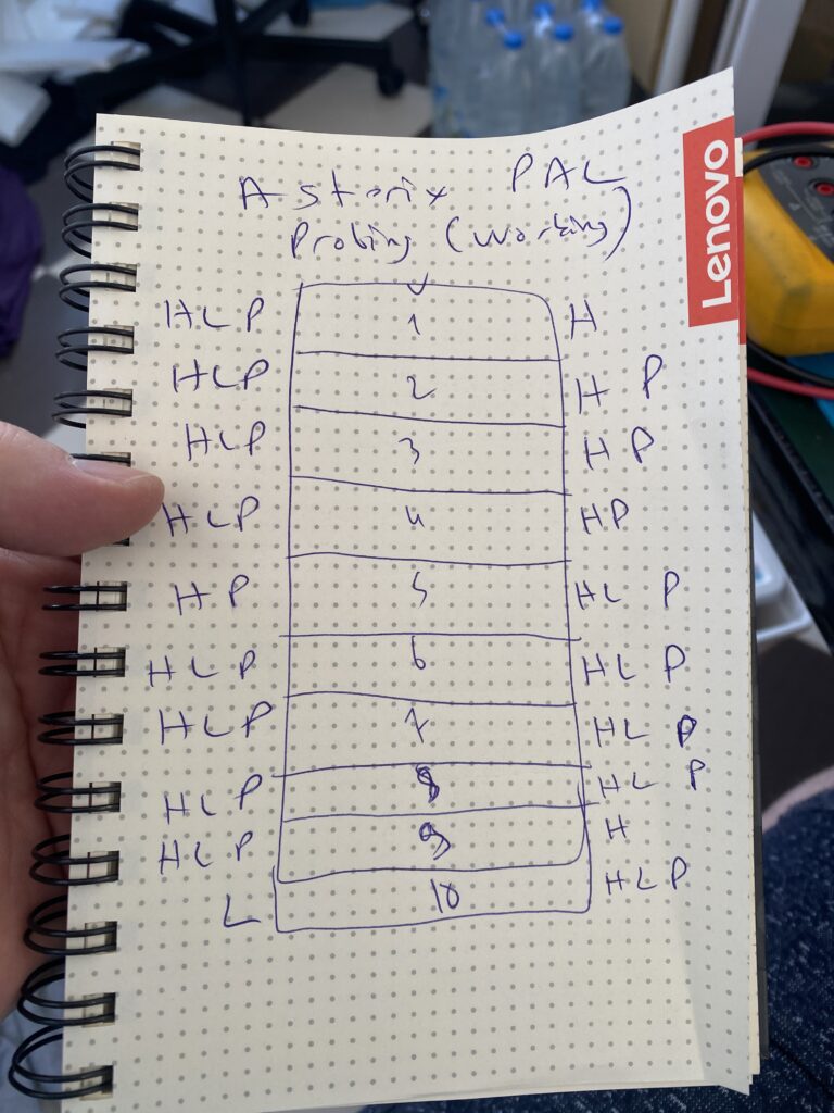
With the Logic Probe, I test the pins of the working and non-working board and compare the results. I do this test by powering each board off and on repeatedly through the startup diagnostic checks.
PAL TEST
H -> High L -> Low P -> Pulse
Not Working BoardWorking Board
Quite different. There is no pulse on several lines on the non-functional board.
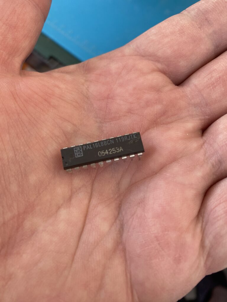
I’m confident that this PAL is the problem, and since I don’t have any GAL, I removed the PAL from the working board. You know the rule that if it works, don’t touch it? Arcade boards don’t have this rule 😀
Here is the functional PAL, transferred from the working board to the non-worked board and socketed:
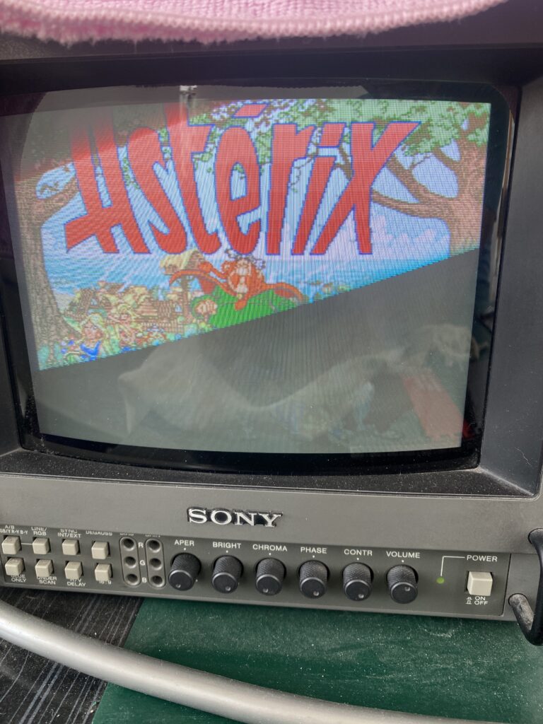
Time to power up!
PFFFFFFFFF. Just when I’m about to give up, something catches my eye. Did you see it? Look a little closer..
Yeah, right there… The IC with the F emblem. It’s a flip-flop circuit. But the important thing here is the brand. Fujitsu ICs are the most prone to failure. I take my Logic Probe in my hand and start probing from the top right pin on the chip (VCC). Let’s power up the board again…
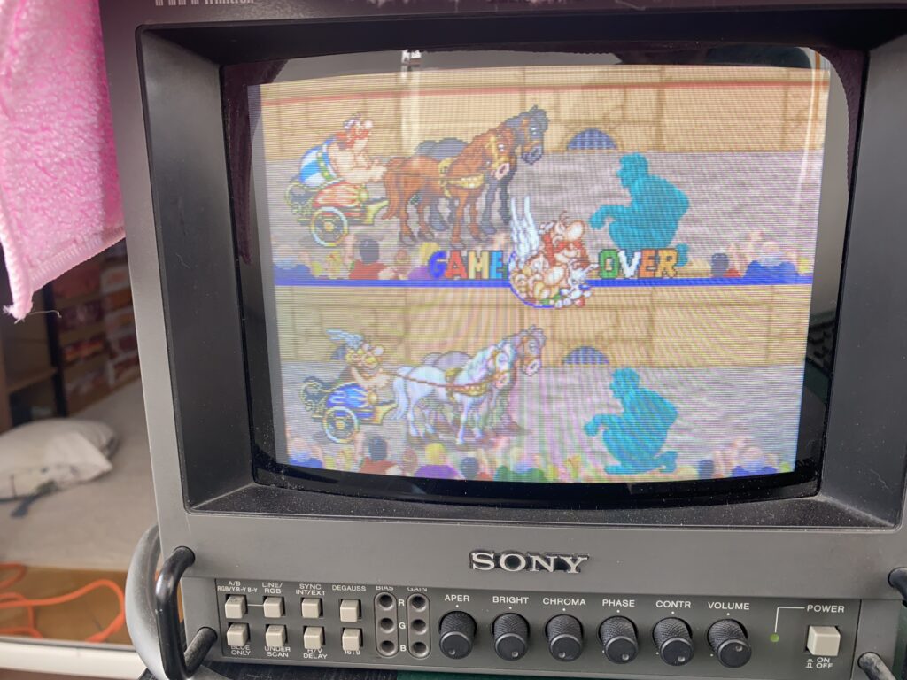
Whoa! Before I can understand what the probe is saying, I hear horse footsteps…
I don’t know what happened, but the board works now. I set the board aside for two days, and when I tried it again, it works fine. I have no idea if probing the VCC pin of that Fujitsu IC triggered something, but it works. I did not change out that part yet because it is working for now.
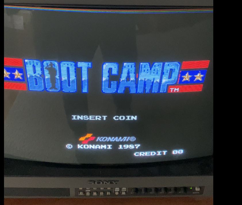
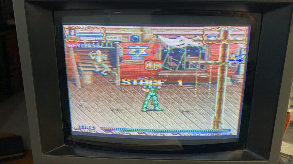
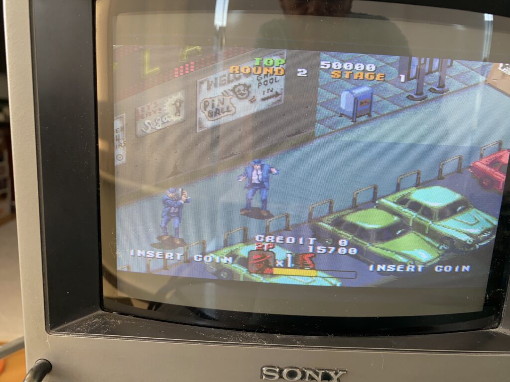
Hello everyone, this won’t be much of a repair article but stay with me. This game is Konami’s Boot Camp. Actually this name is the name published in America – in Europe we know this game as Combat School. It is one of my favorite games. I thought it was the same between regions and bought the USA version, but there was a difference – the American version is played with a trackball, not a joystick. I will convert my board to play with a joystick at some point.
Here is the board I received:
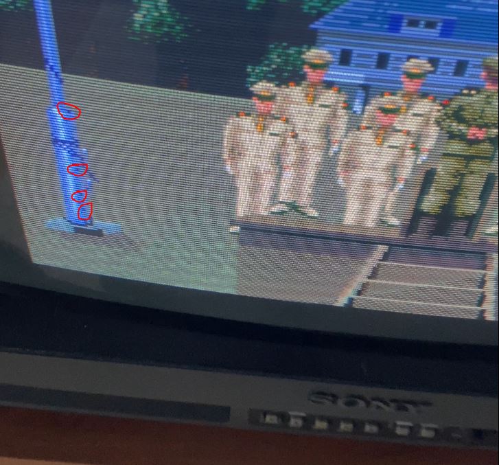
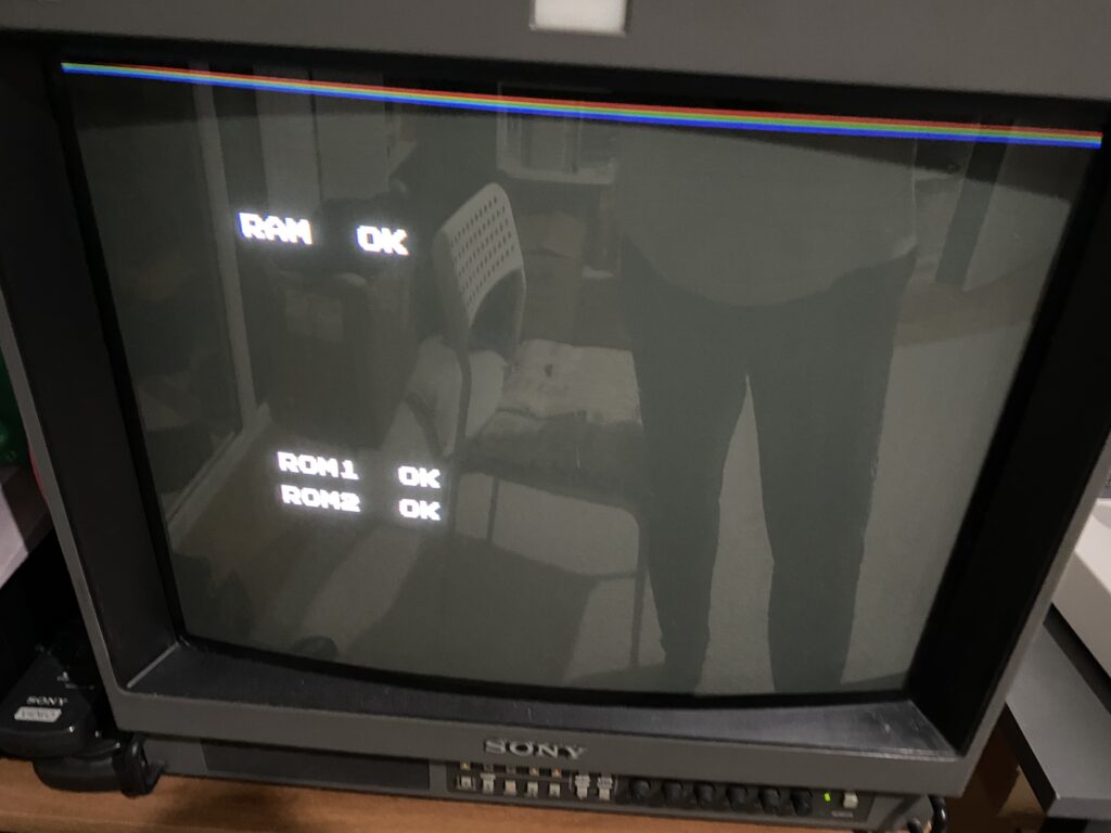
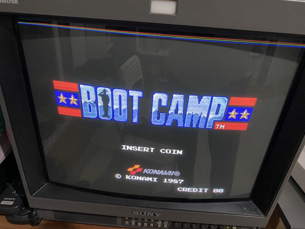
The board was sold to me in “working” condition, but when it arrived I encountered a problem. At first, the RAM & ROM Startup Tests pass successfully: and the title screen appears as it should:
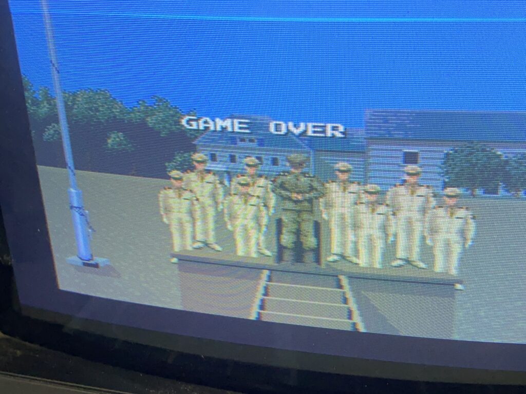
But along the top edges of the title logo and inside the game itself, there is random pixel corruption everywhere. The circled pixels on the flagpole shouldn’t be there.
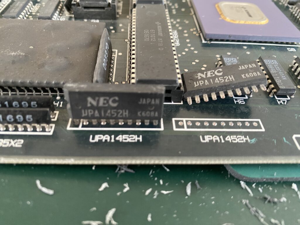
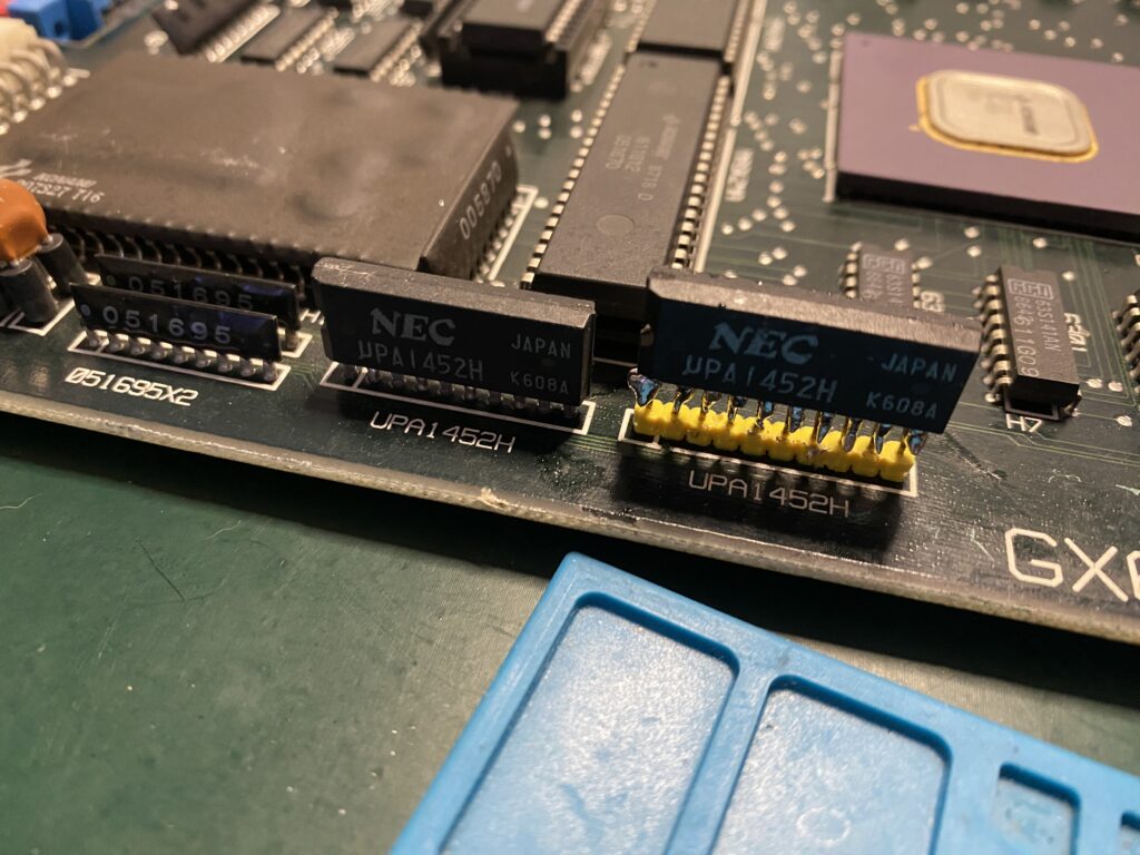
Then, when positioning the board to start investigating the problem, I realized that a part of the board is very fragile because when I touched it, it fell off!
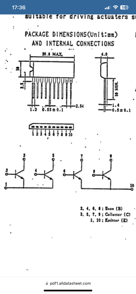
If you ask what this IC “UPA1452H” is for, I will quote you directly from the datasheet:
[i]“µPA1453 is a PNP silicon epitaxial Power Transistor Array built
in 4 circuits designed to drive solenoids, relays, lamps and the
like.”[/i]
I think this must be a component on this board that drives the trackball. Obviously this is a problem and I wanted to solder the IC back onto the board, but since the legs of the IC snapped off they cannot be soldered properly. So I used a header pin as a dirty and quick solution.
NOTE: Of course it won’t stay ugly like this. As I said at the beginning of the article, I will convert this board to a joystick version later on – when I do, this component will be removed in the conversion process.
After reinstalling that IC, now everything functions normally.
Hello everyone, today I have another board on my desk which I purchased as “working” but while my board boots up, it has issues.
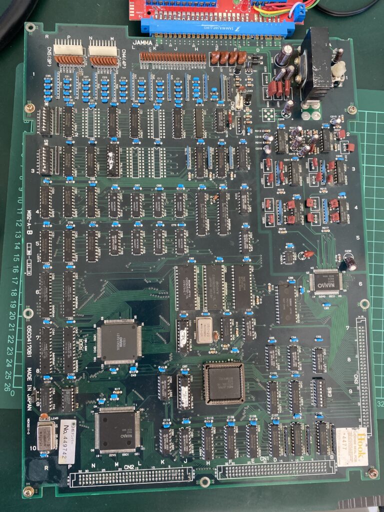
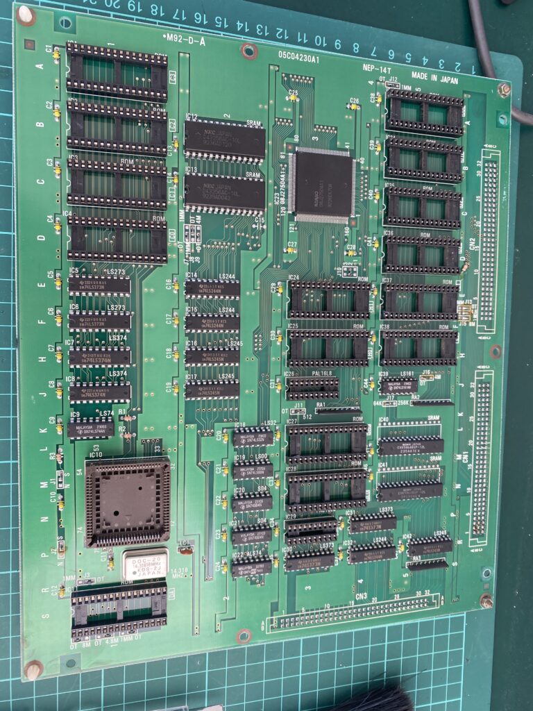
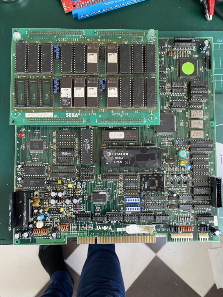
Irem produced several models of motherboards, and this motherboard is M92. It is a 2-stack board, consisting of a motherboard and a ROM board. M92 does not have any schematics. [Editor Note: wickerwacka produced some partial schematics of the M92 when implementing his FPGA core. Also take a look at our Irem M92 entry in PCB Encyclopedia]
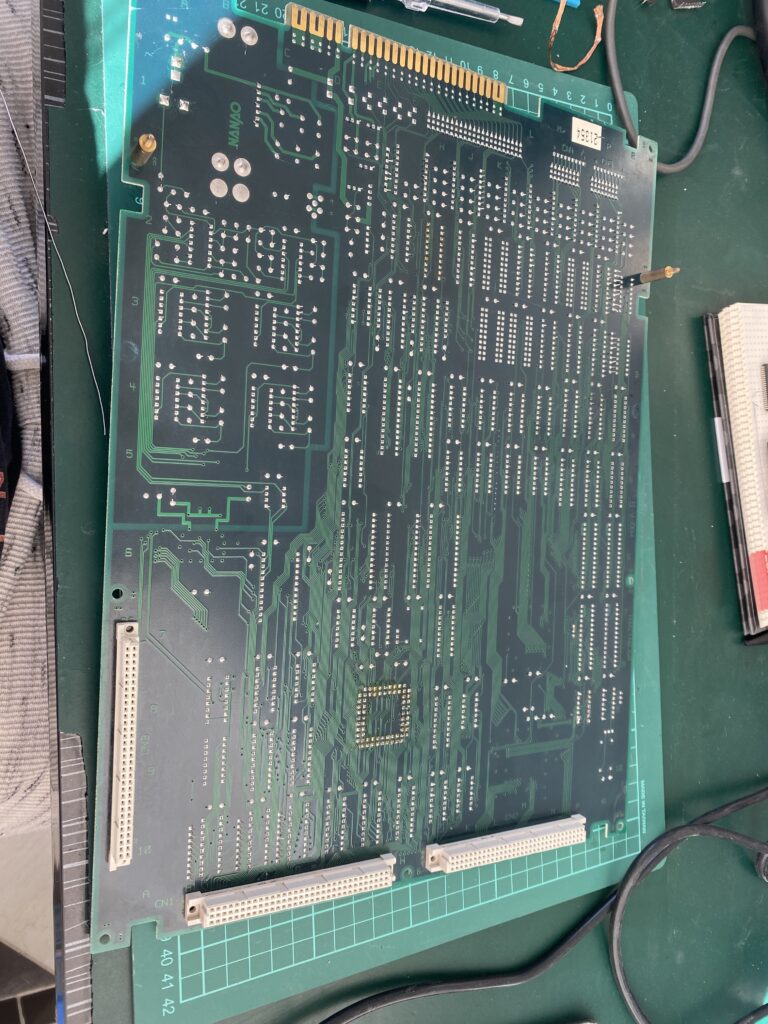
First let’s take a look at our board. Main board:
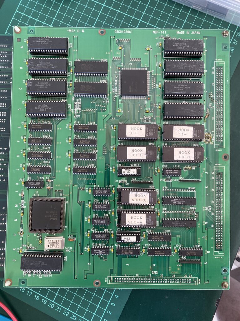
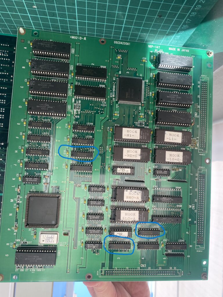
ROM Board
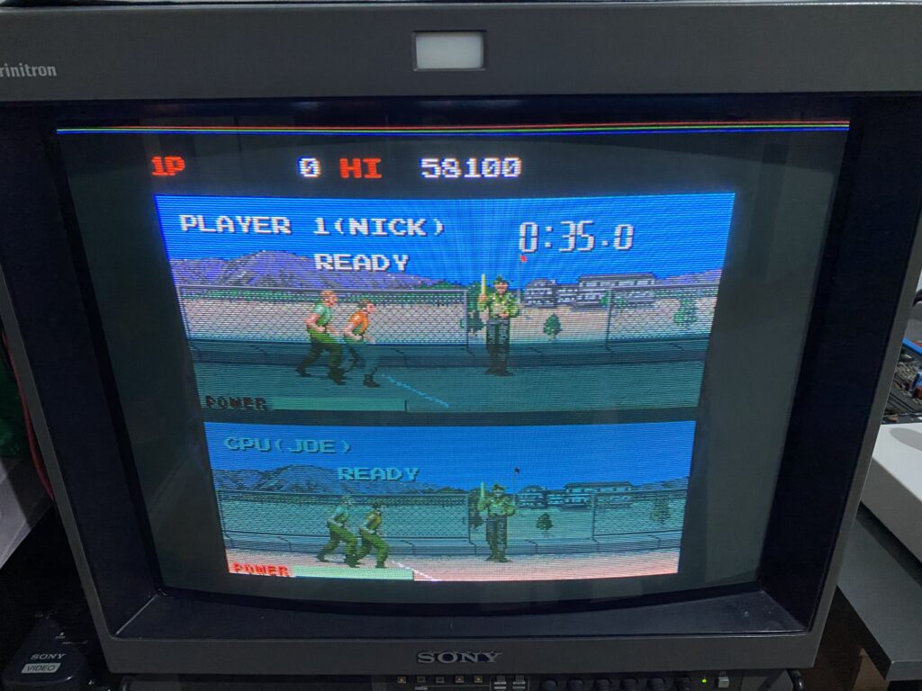
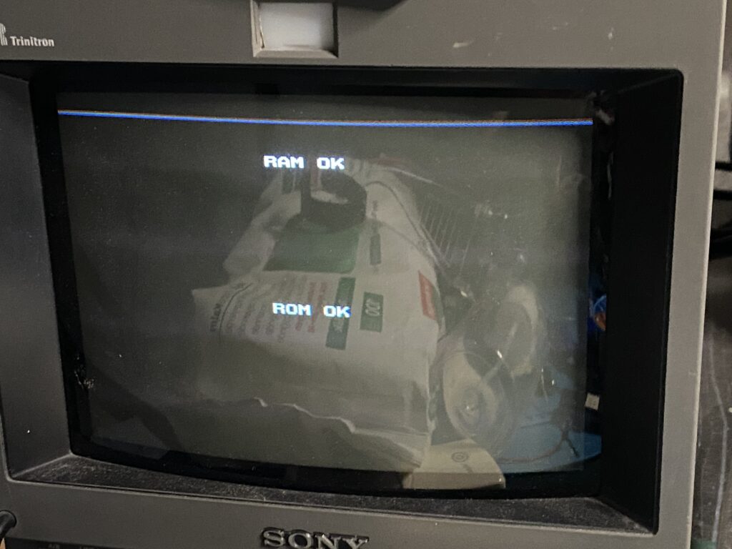
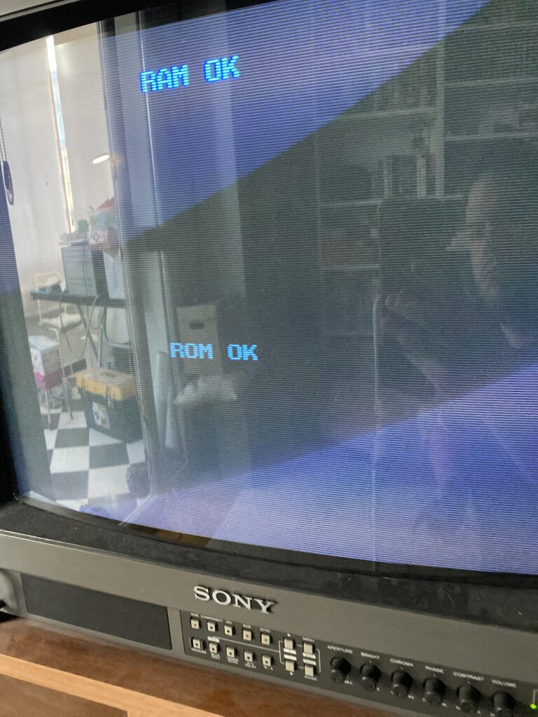
When I power up the board, it passes the RAM and ROM test successfully.
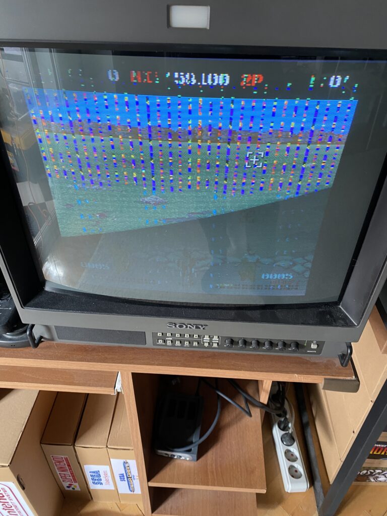
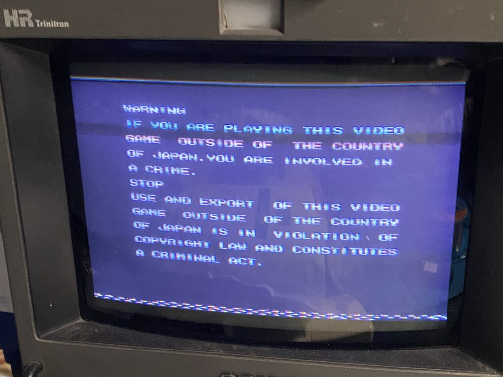
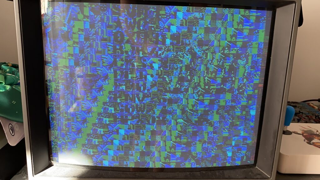
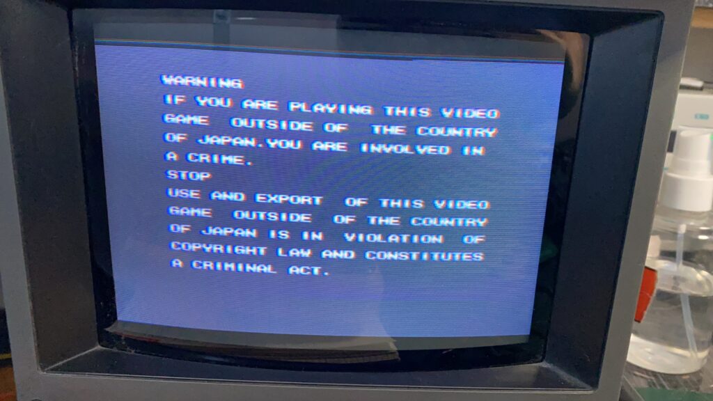
However, in the warning text, you will see a line at the bottom of the screen. That’s one of our problems.
Here you can see another problem, there is a vertical line on the left and right of the screen.
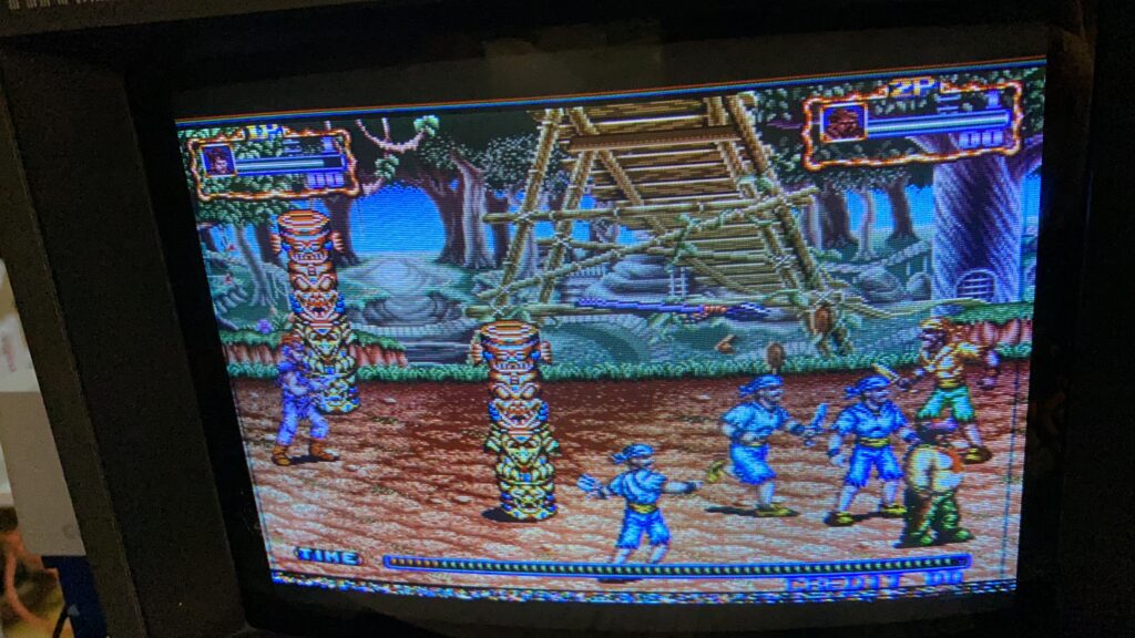
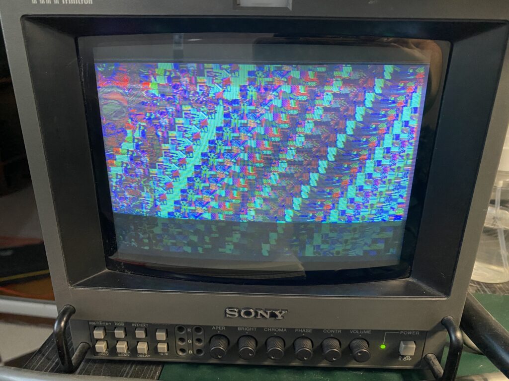
These are the most obvious problems. It is difficult to show the real problem with a photo. Take a look at this video of the problem:
As you can see, as our character moves forward and the background changes, there are flashes and/or color changes on the screen. This is our biggest problem.
Let’s do a physical inspection. The ROM board seems clean and problem-free enough. I move on to the motherboard.
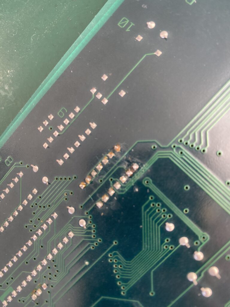
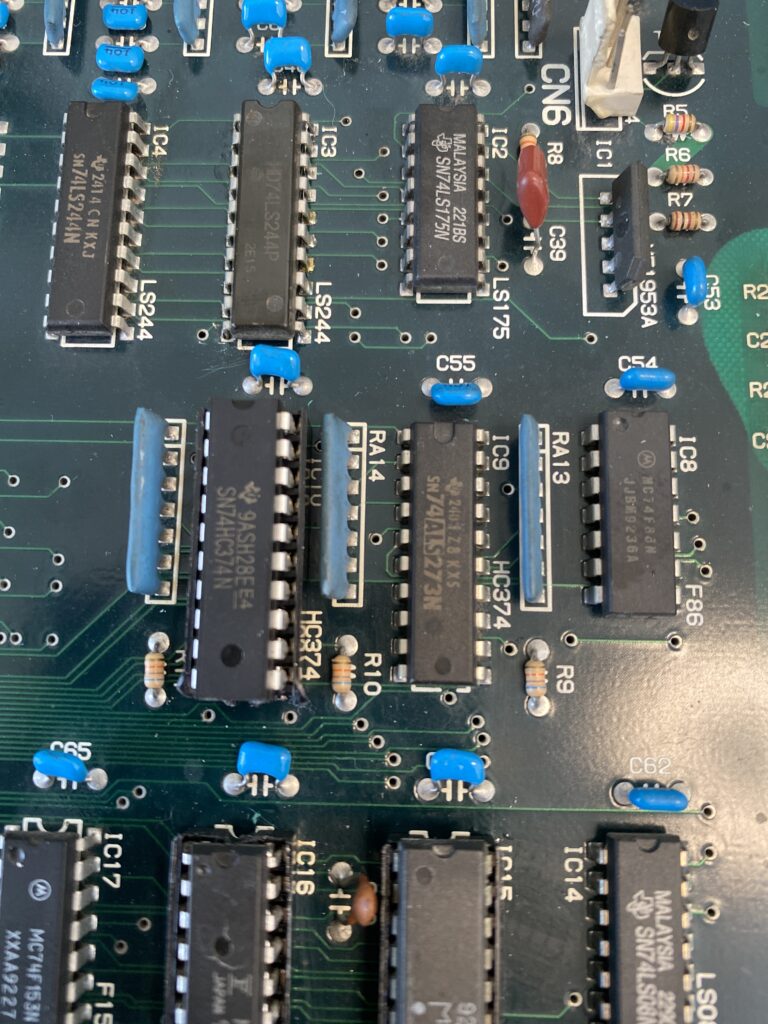
The mainboard has been worked on before – one of the chips has been changed or reflowed.
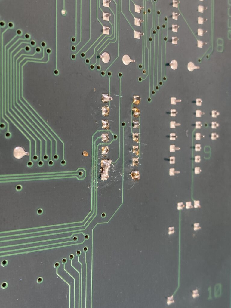
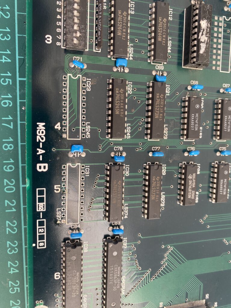
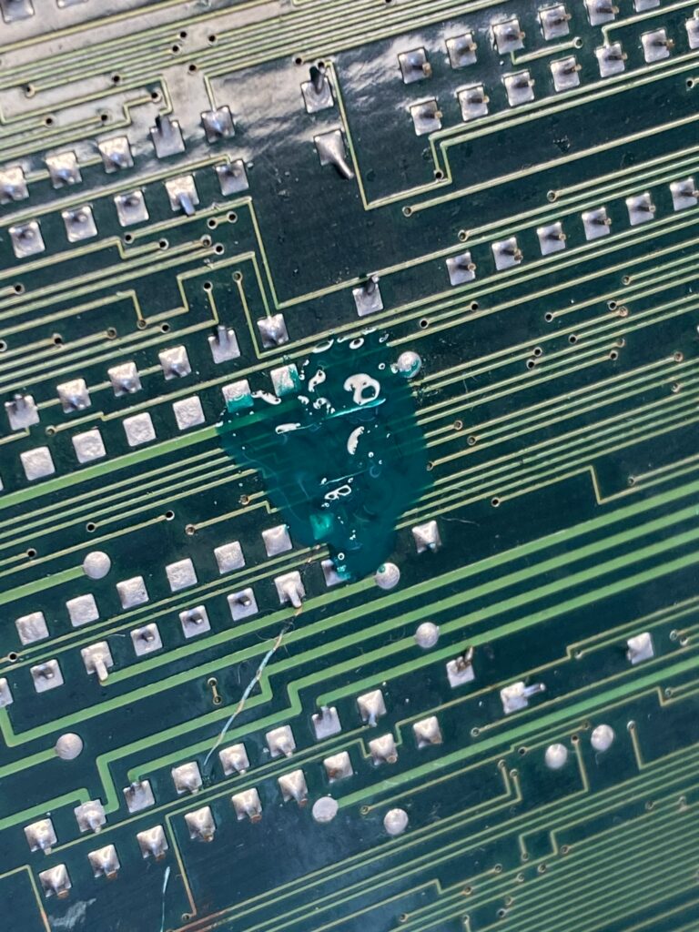
When I look closer, I see a solder bridge. This bridge belongs to 74LS74AN part.
I separate the bridge with a tiny touch of a soldering iron.
But removing this bridge causes no change with the game.
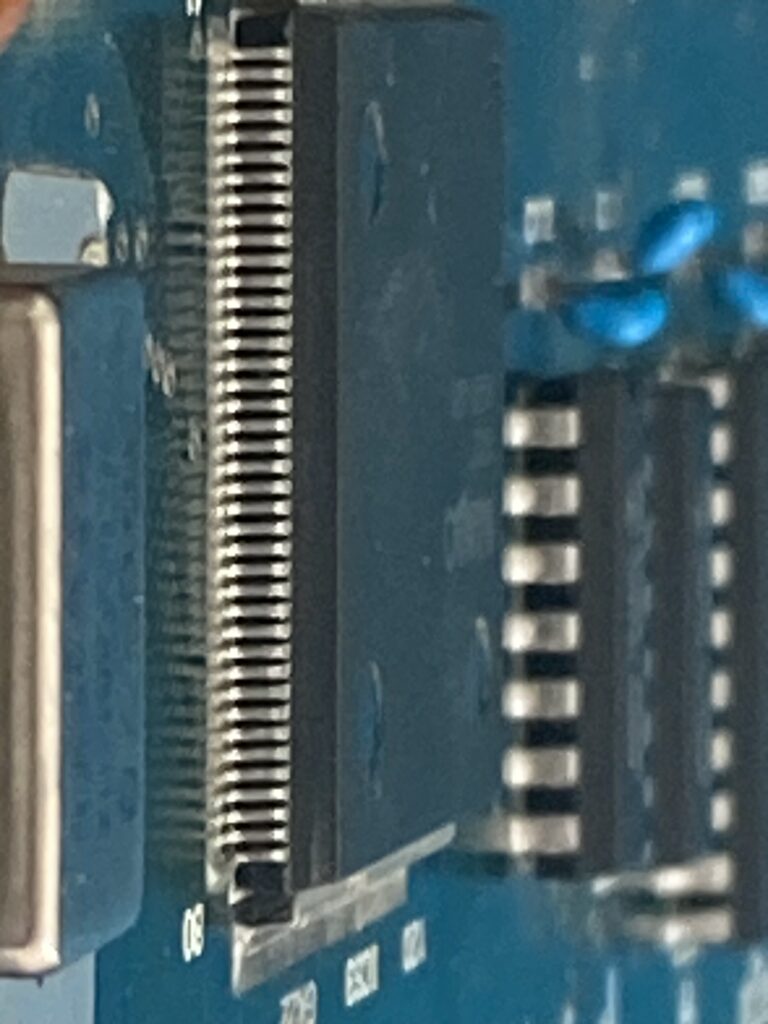
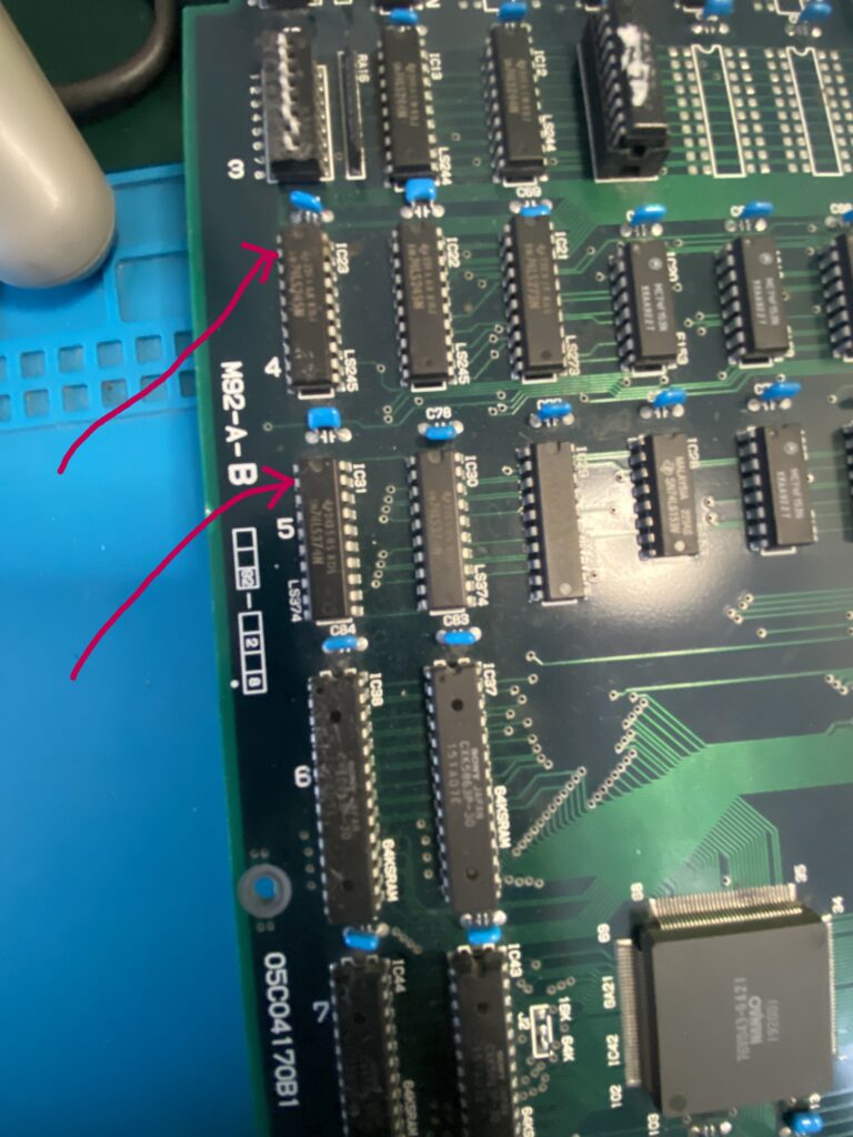
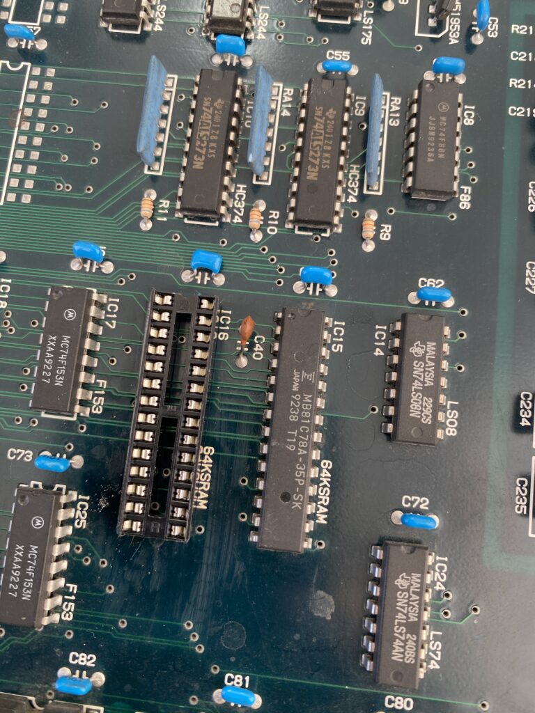
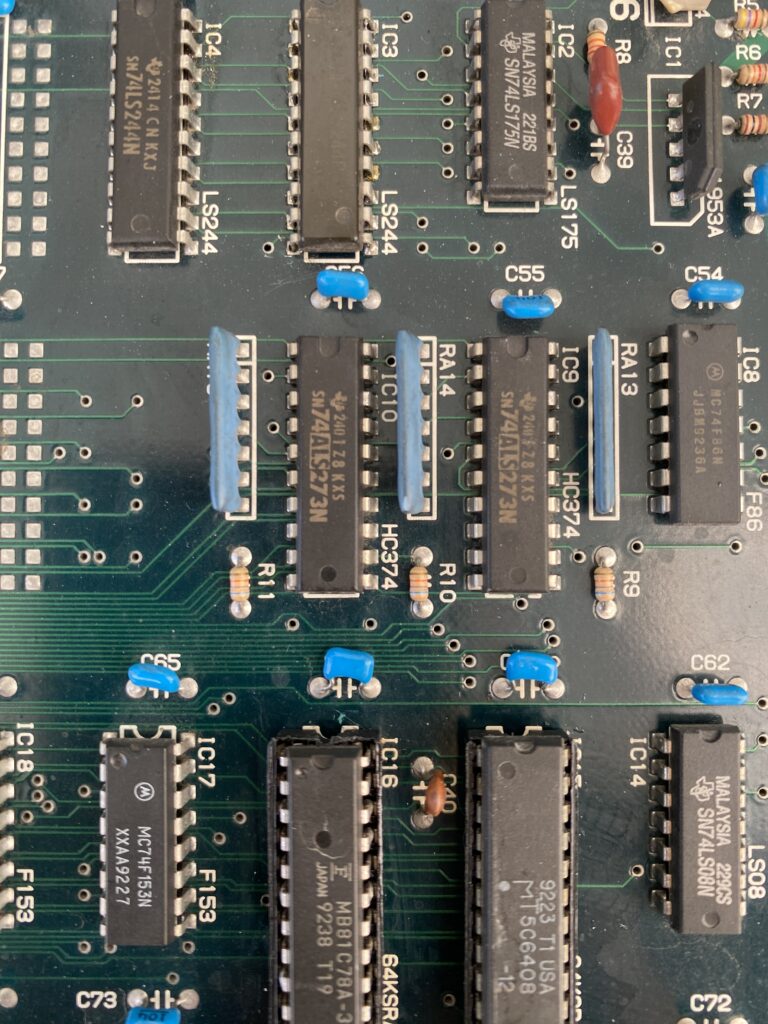
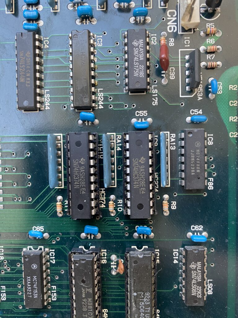
Next, I keep the game on for about half an hour, then I check the chips one by one to see if any of them are overheating. It seems that three of the ICs on the ROM board, which I have highlighted in blue, are overheating.
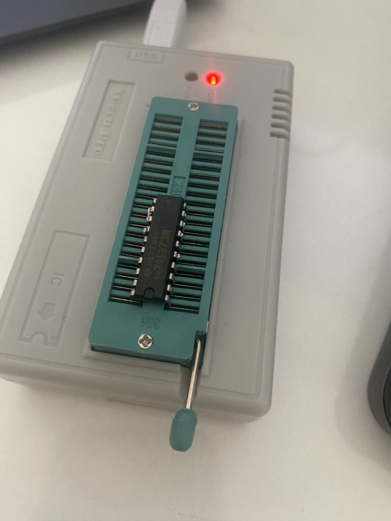
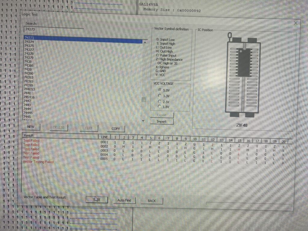
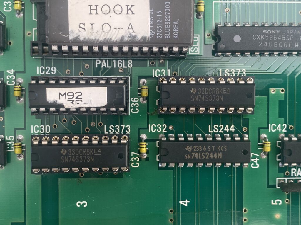
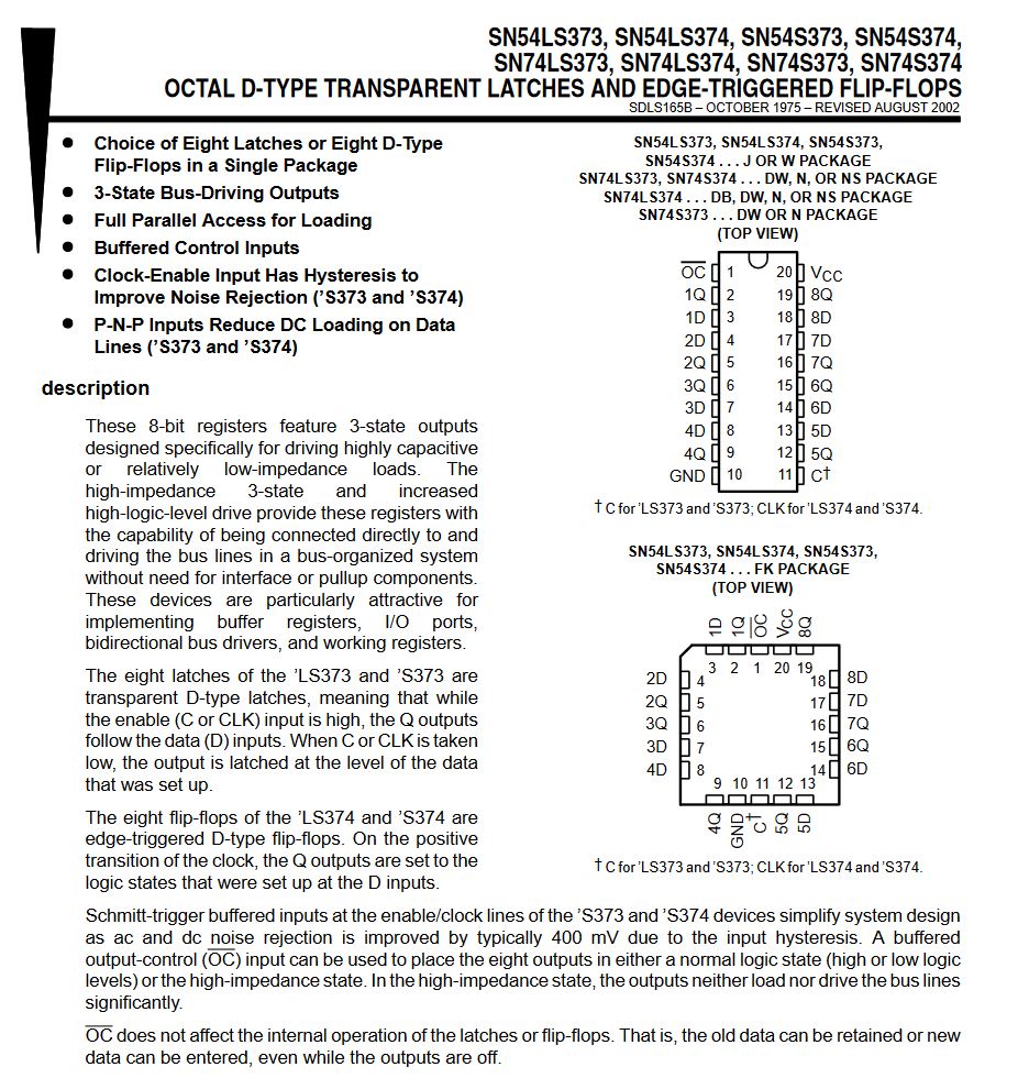
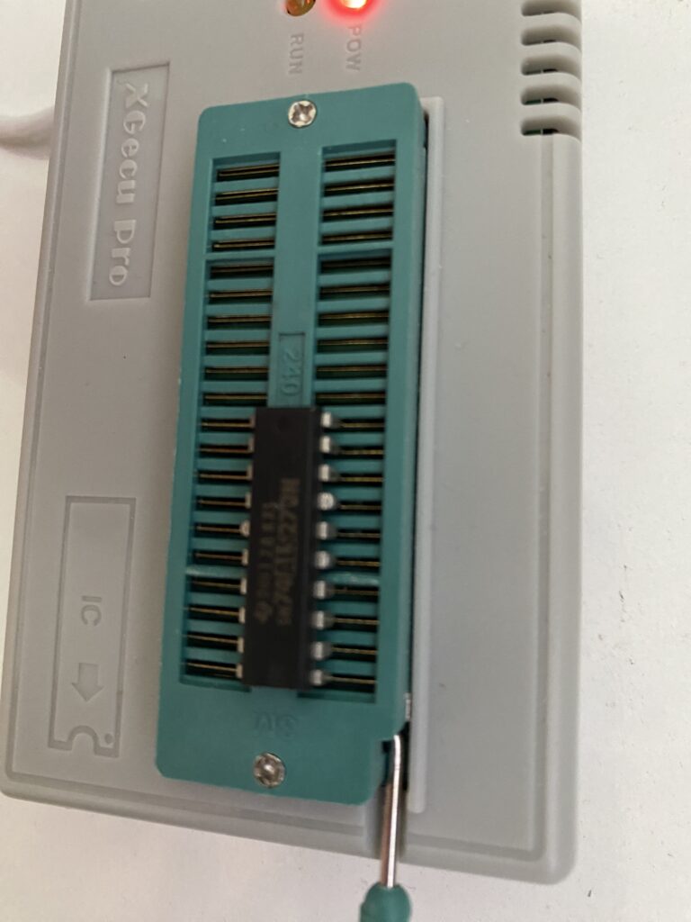
One by one, I remove the parts and test them out of circuit with my EPROM programmer. One of the SN74S373N parts fails the test.
I install socket and replace all three parts.
IC18
IC30 and IC31
Unfortunately, there’s no change in the game – but there’s no more overheating chips now either.
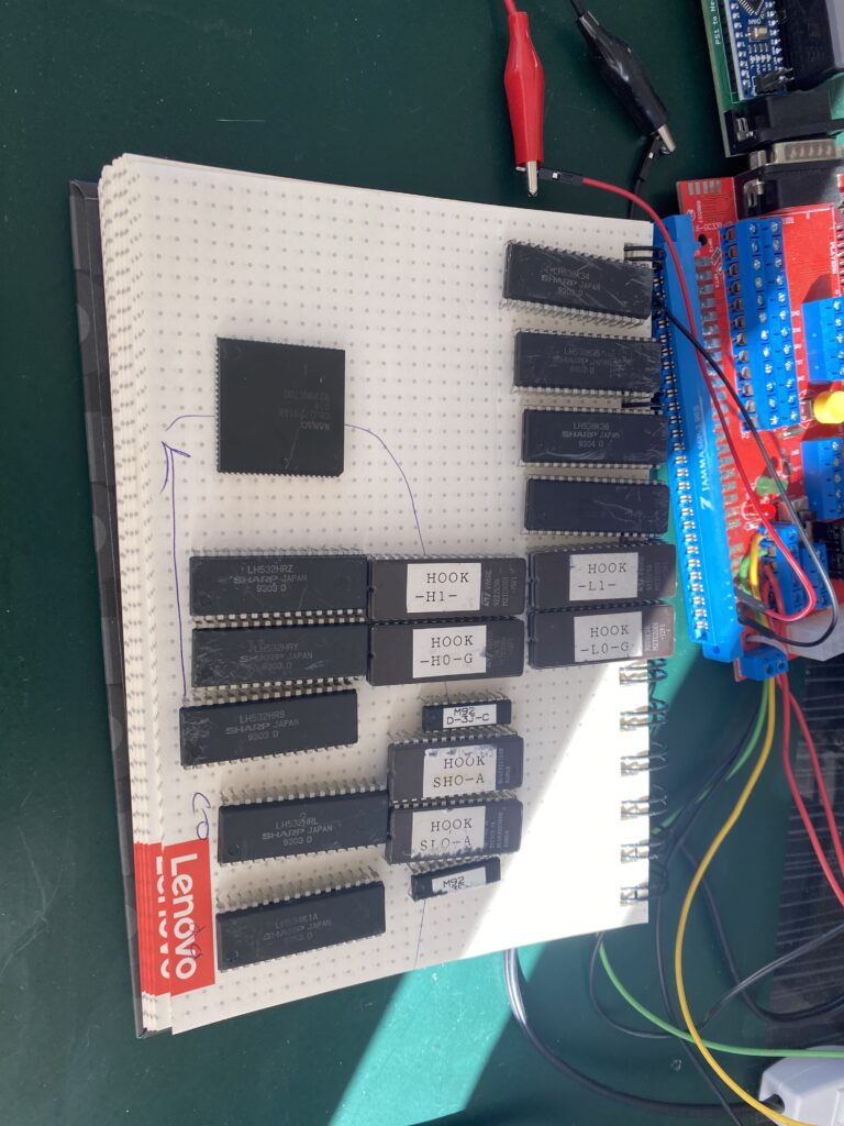
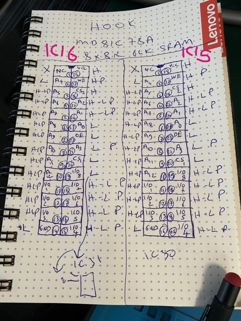
The next task is to check the ROMs by dumping them and comparing the dumps with MAME. I remove everything from the ROM board (both for cleaning and to check the ROMs)
I set the chips down on a notebook in the same order so I don’t forget their places.
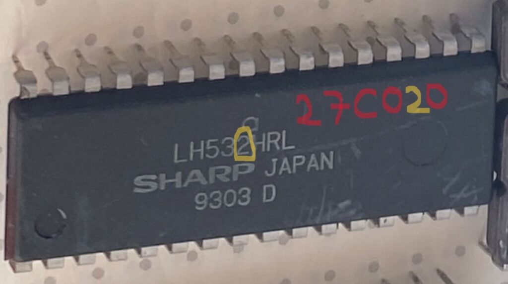
When dumping the ROMs, if it is not written on the chip you are reading what type of part it is, we either check MAME or we look for solutions in forums. [Editor Note: the part numbers for ROMs with Irem M92 boards are in our PCB Encyclopedia]
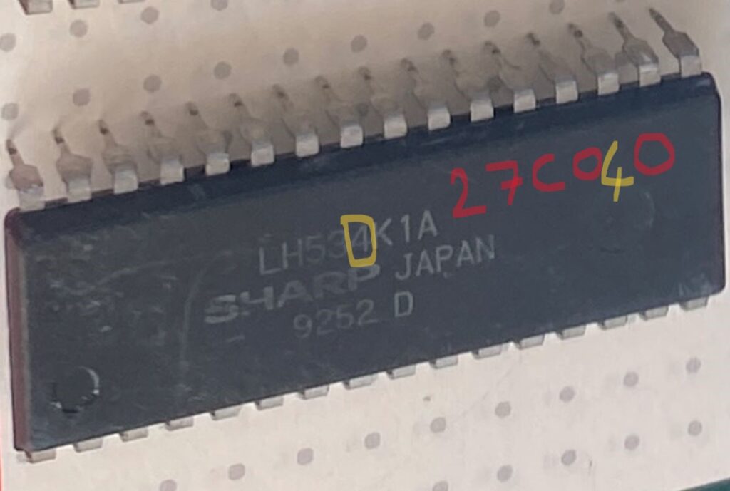
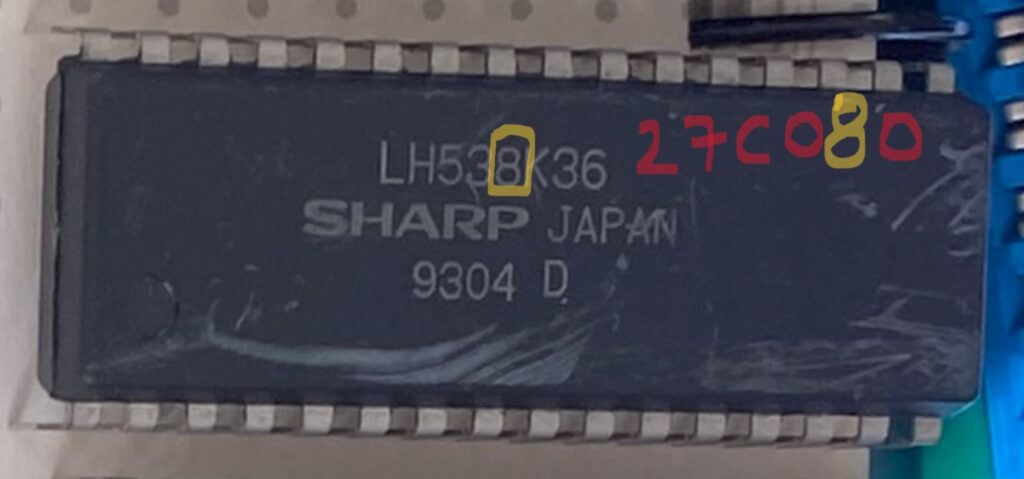
There were 3 types of ROMs on this board. Let me specify how to read them:
532 –> 27C020
534 –> 27C040
538 –> 27C080
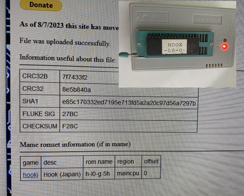
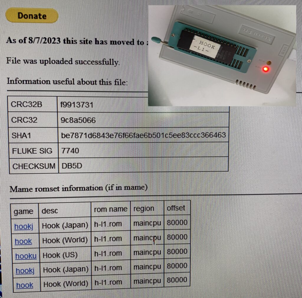
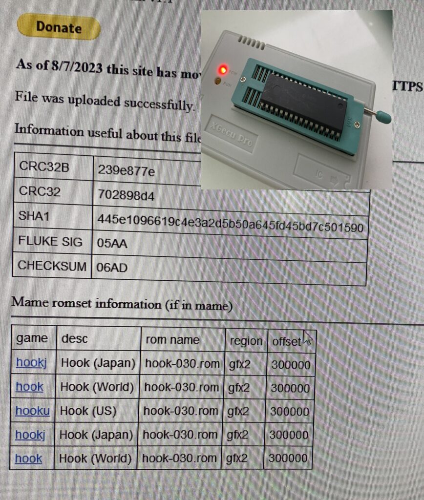
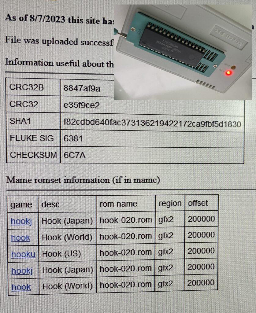
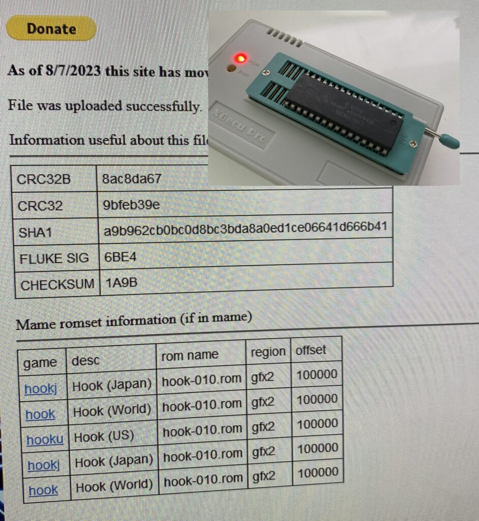
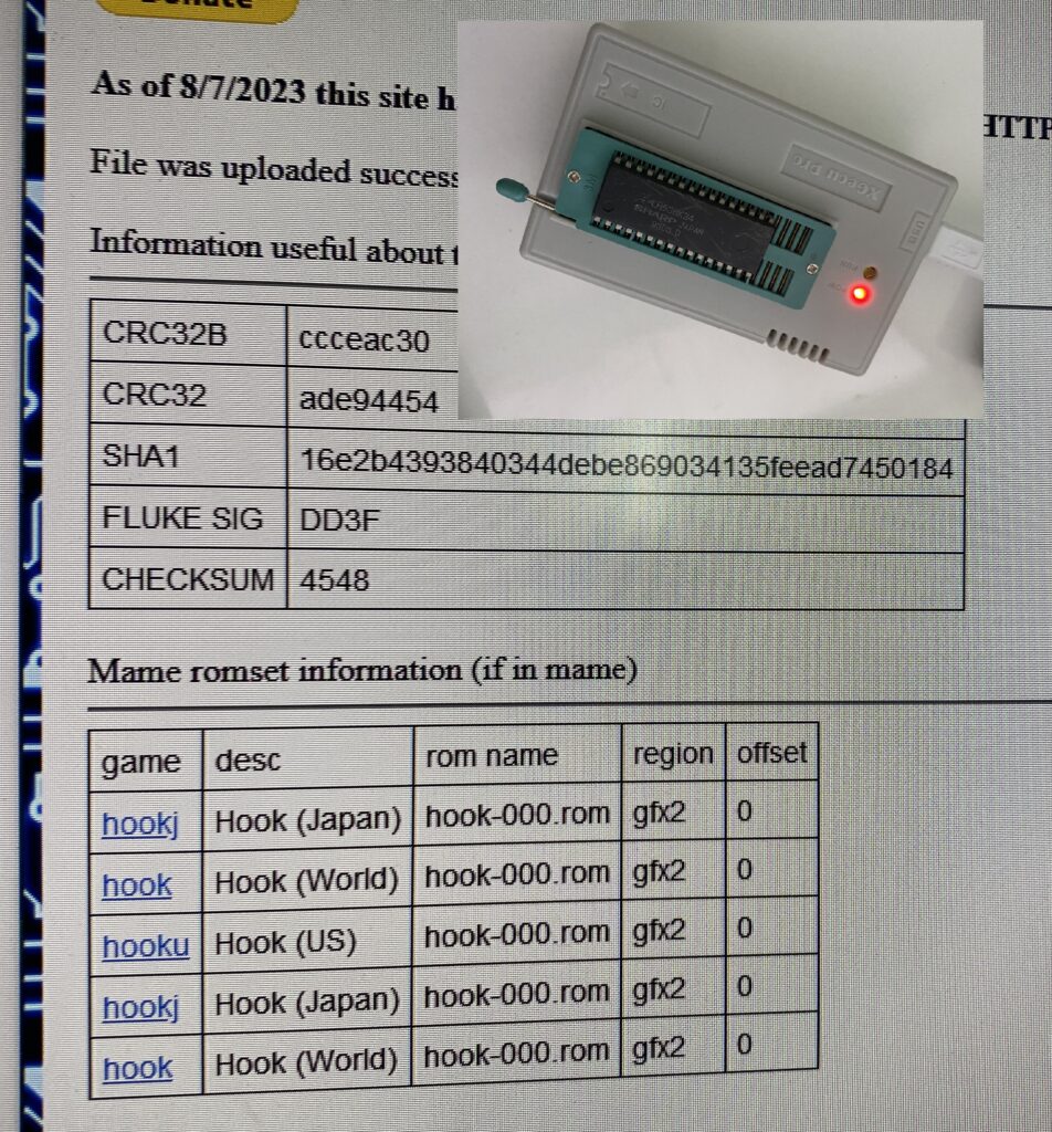
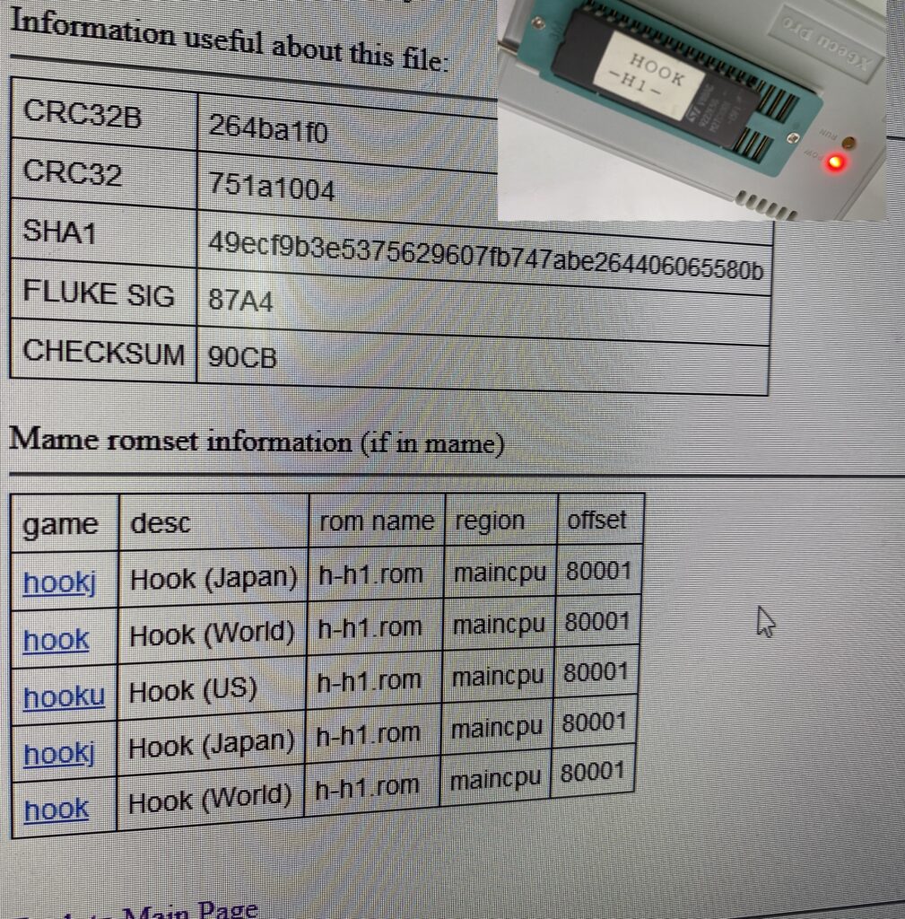
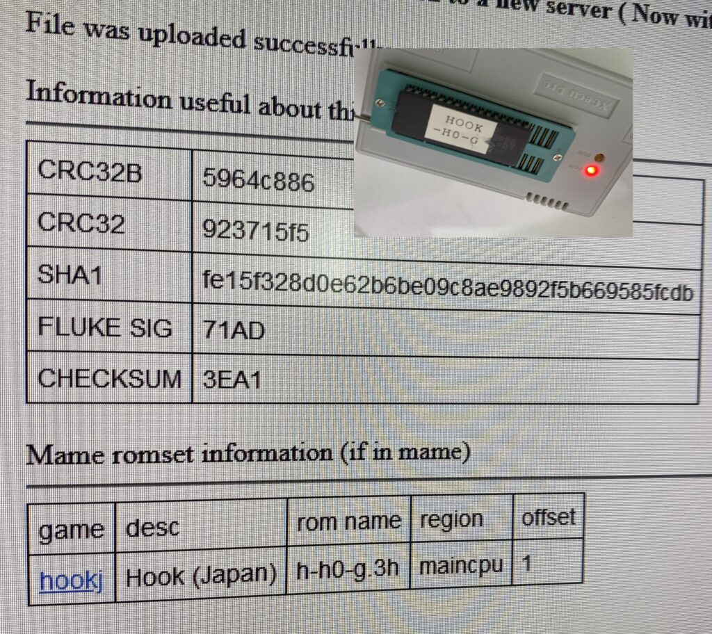
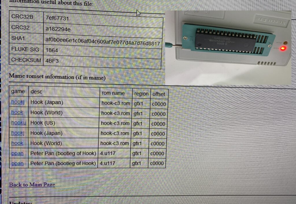
After dumping the ROMs and comparing them, it seems that most of them are okay.
L0
L0L1030020010000H1H0C3C2C1C0
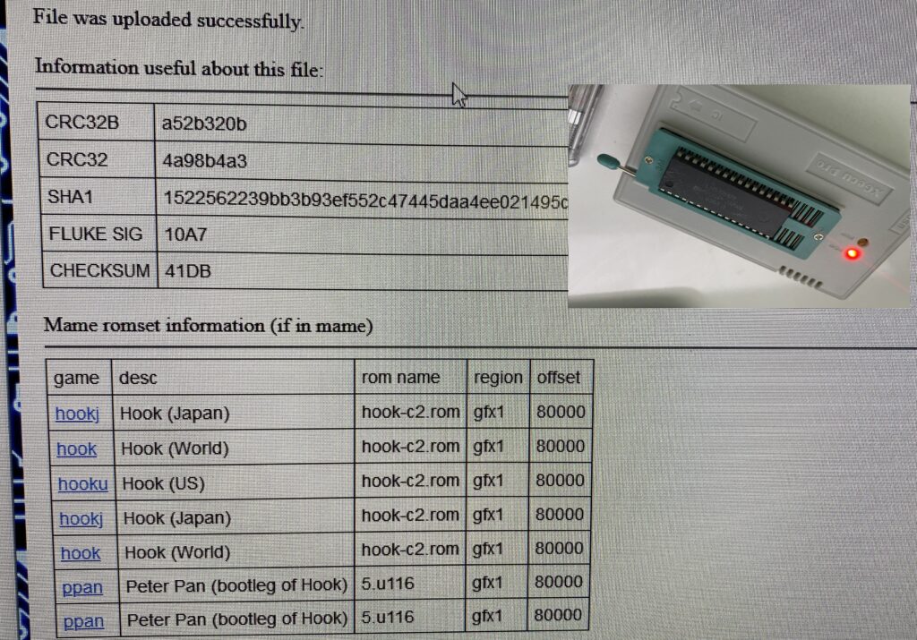
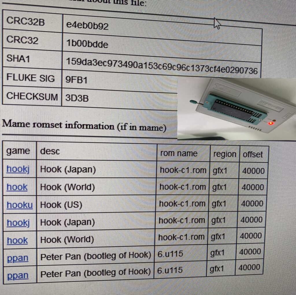
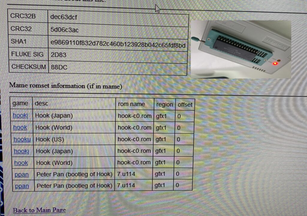
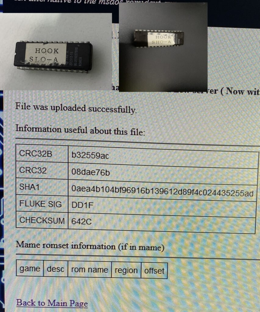
Then I had problems with 2 ROMs – both audio ROMs.
SLO-A and SHO-A
The ROMs are responsible for the playback of all sounds. These ROM comparison sites do not list results if the ROM dump I provide is not 100% identical.
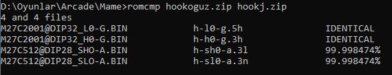
The sound works on this board, so obviously our problems have nothing to do with the audio ROM. I won’t dwell on it, but I’d still like to check how close the files are. Here’s what the “romcmp” command in MAME says about my dumps compared with the correct MAME ROMs:
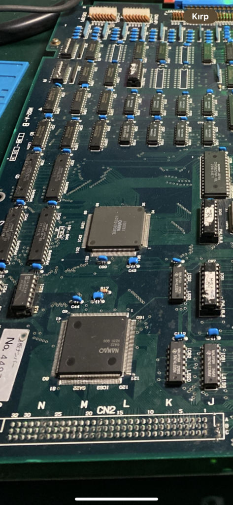
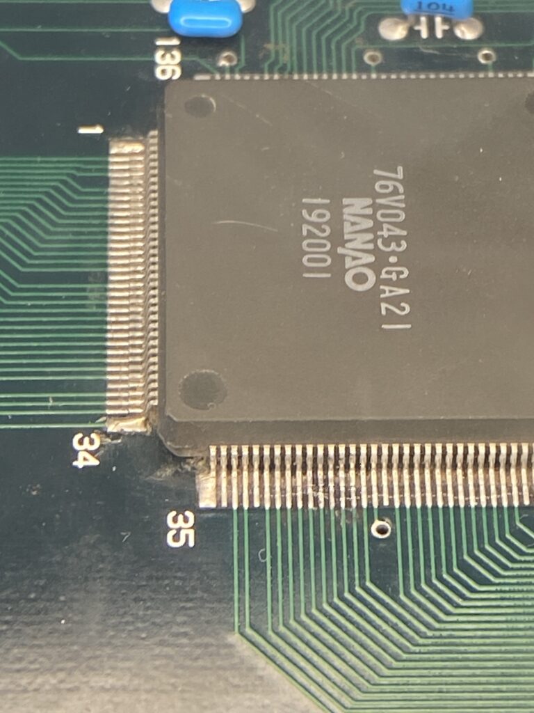
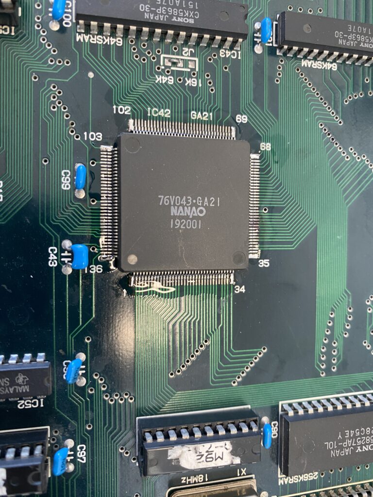
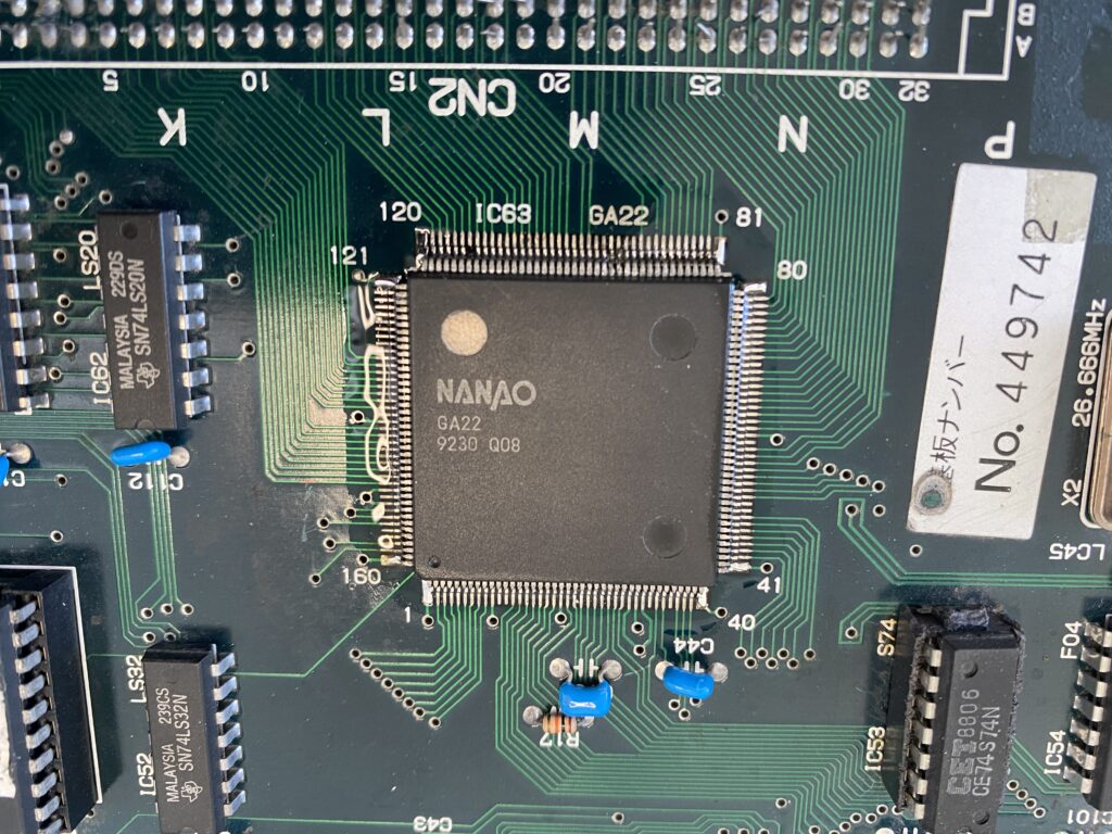
Next, I am inspecting these two large GA (Gate Array) chips. These are custom chips – when they fail, it is a nightmare to source replacements. Sometimes reproduction parts are created by the community but otherwise you have to source parts from a donor.
GA21 and GA22
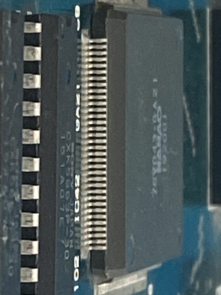
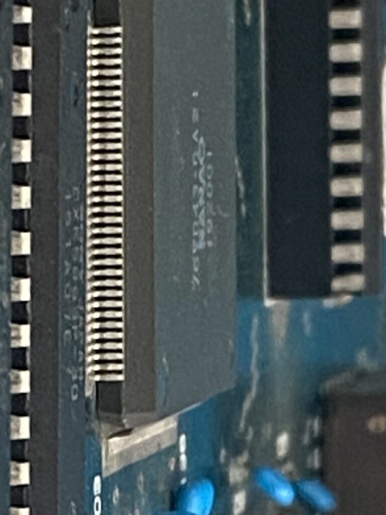
I check the connections of the legs with the boards by gently poking them with an X-Acto knife. I also perform a continuity check with a multimeter to see if there are any bridged paths.
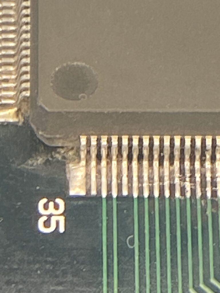
I don’t detect any non-contact legs, but I detect continuity in legs 35 and 36 in GA21.
Up close, I don’t see a soldering bridge.
Later on, I asked a friend who has the same board to check on his board, and he gets the same measurement, so there is no problem with these pins. On my board, I reflowed the solder on them just in case.
I went ahead and reflowed the other GAs too.
When testing the game again afterwards … the result is the same. I still haven’t found the culprit…
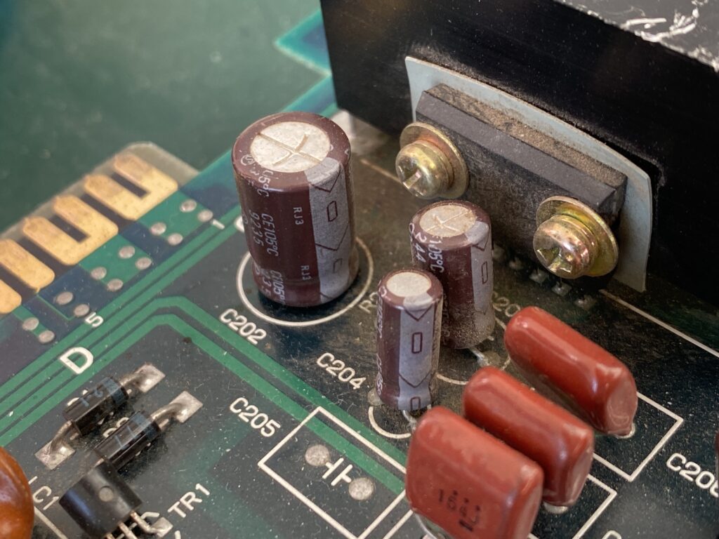
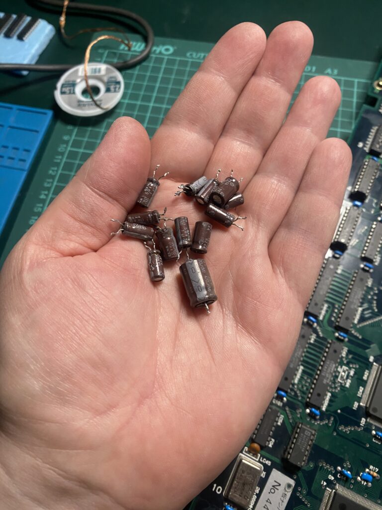
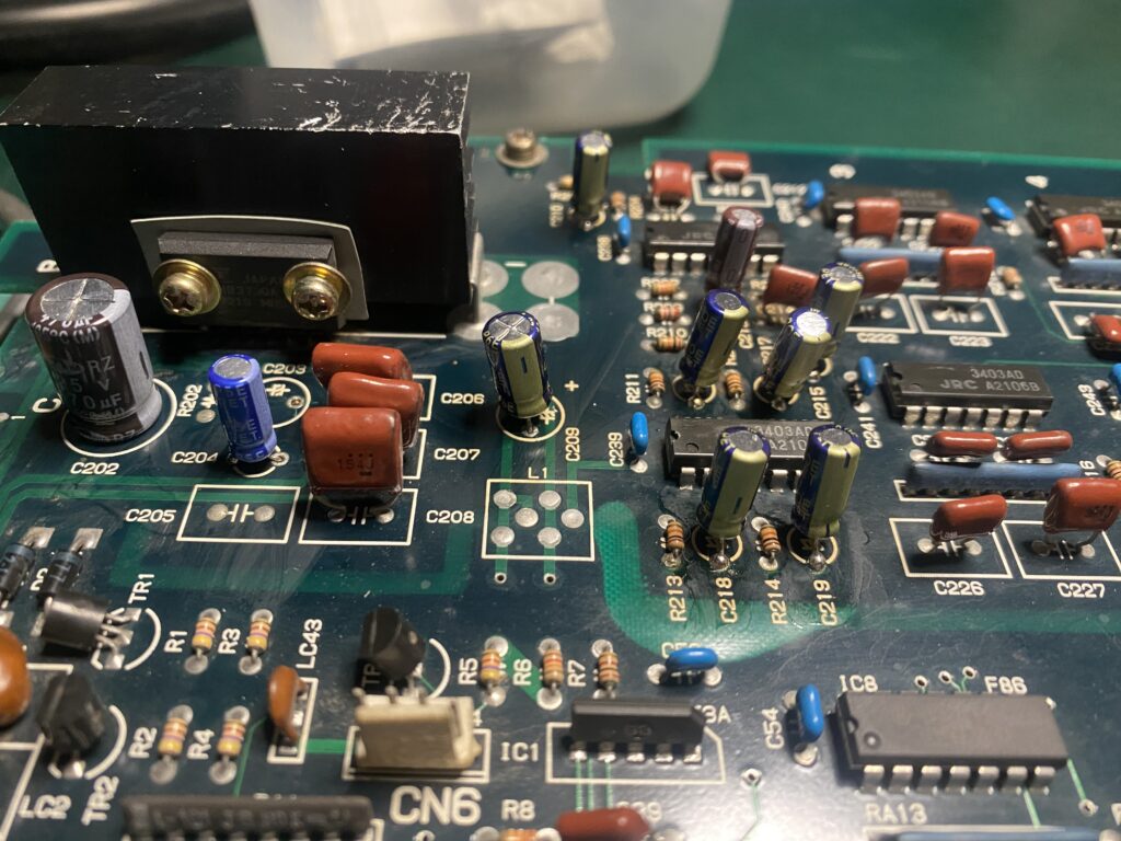
I’m growing weary with this board, but I wanted to get one more thing out of the way. There are 14 brown ELNA capacitors on the motherboard. These capacitors are very prone to leaking so I thought I would replace them.
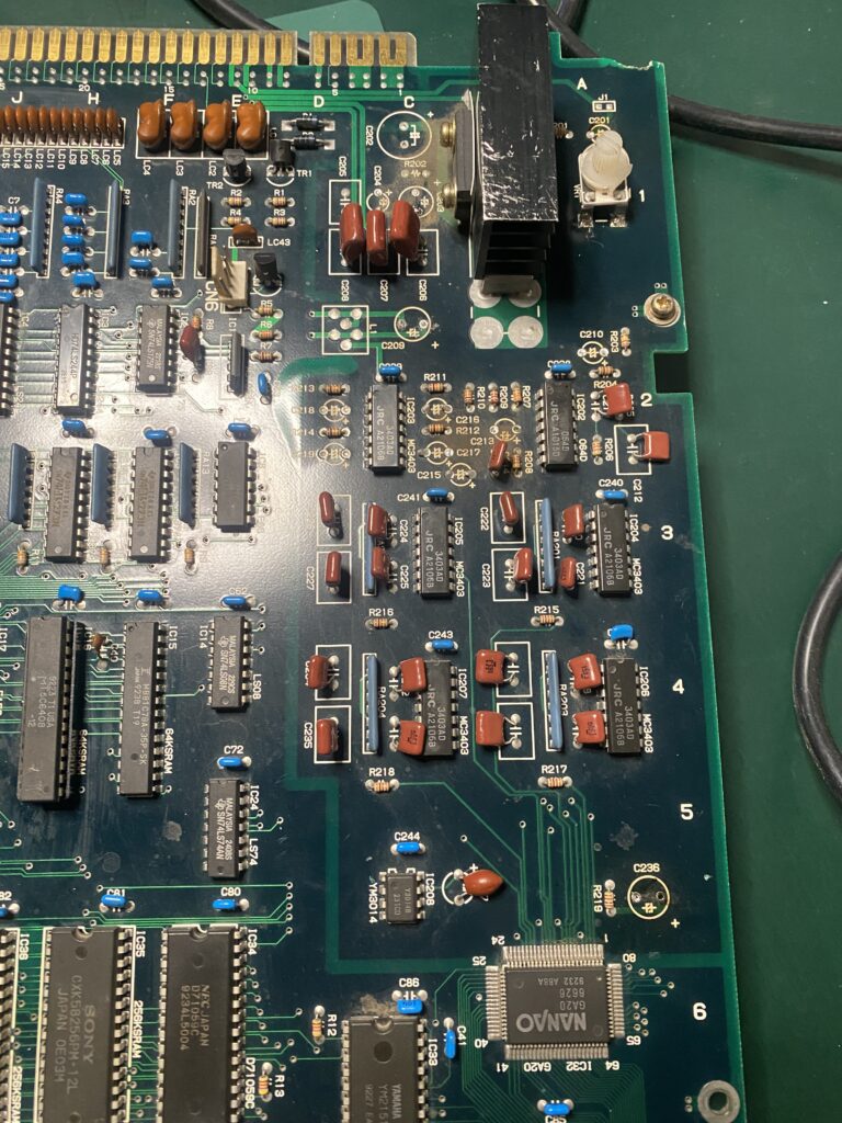
And here’s the board after installing the replacement caps.
If you’re using a hot air gun, be VERY, VERY careful! This area highlighted in blue swelled on my board-fortunately I didn’t damage anything. I dodged a bullet.
After recapping, the previously almost inaudible game sound now sounds great!
Now back to the main problem with the horizontal lines at the bottom of the screen, the vertical lines on the right and left of the screen, and the color distortions when the background scrolls.
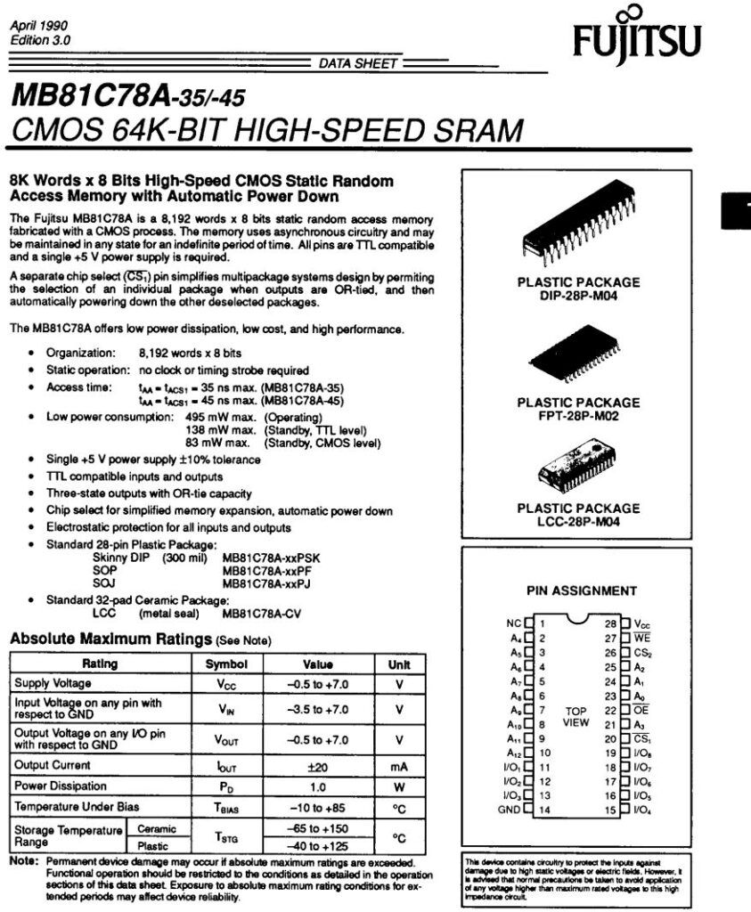
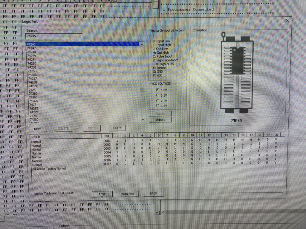
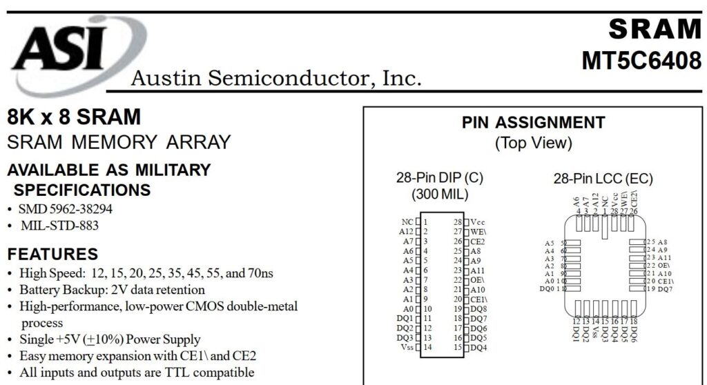
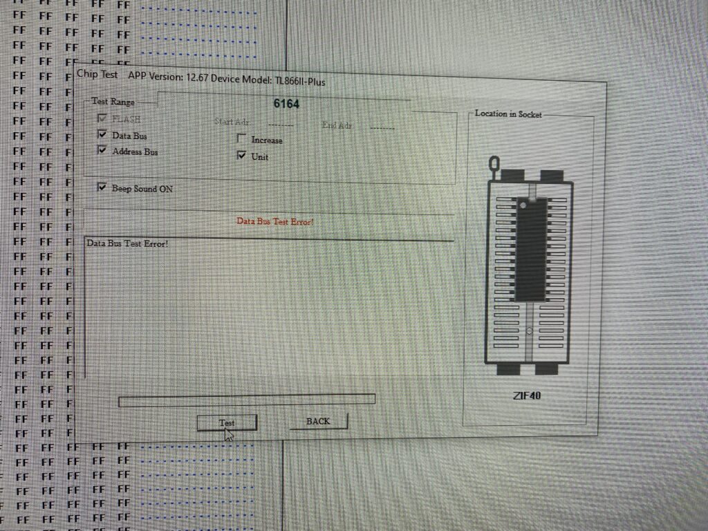
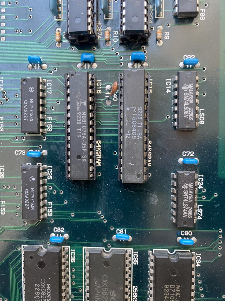
I take out my Logic Probe and start probing. There are two palette RAM chips located at IC15 and IC16 on the motherboard. These parts are Fuji brand – the most susceptible brand prone to fault. The part is MB81C78A, which is 8K x 8 = 64KB of RAM.
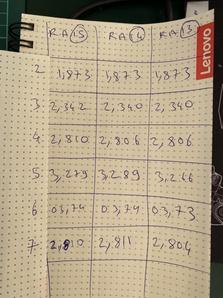
I documented the logic activity of the pins on the two chips by making a table:
According to the data sheet for these memory parts, Pin 19 on these parts is the “I/O 8” data line. When probing this pin, I see a difference between IC15 and IC16.
IC 15 –> Pin 19 –> shows PULSE activity between HI and LOW. So there is a data flow.
IC 16 –> Pin 19 –> LOW only and no PULSE. So no data is flowing.
Two things could be happening here:
1) This RAM chip is bad 2) Or one or more ICs connected to this pin are bad.
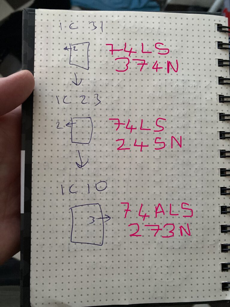
I trace Pin 16 of IC19 with a multimeter and see that it goes to Pin 31 of IC2.
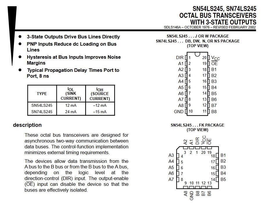
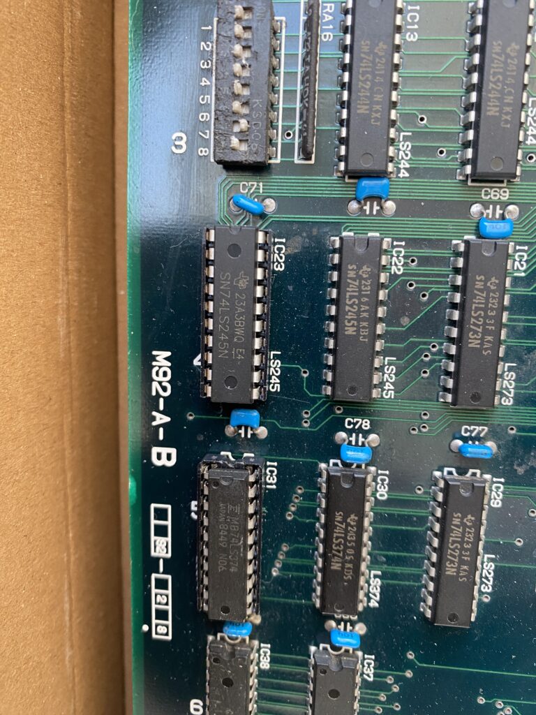
IC2 is a SN74LS374N part. According to it’s data sheet, Pin 2 –> 1Q (Output)
I also find that IC31 Pin 2 also connects to Pin 2 of IC23.
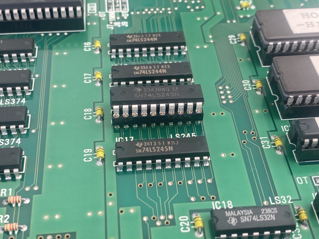
IC23 is a SN74LS245N part. According to its data sheet, Pin 2 –> A1 (I/O)
I remove these parts with the suspicion that they are causing at least part of the problems.
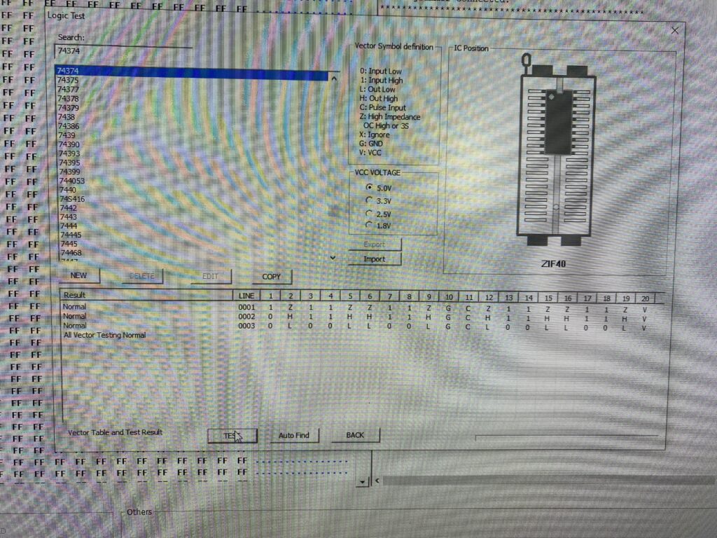
Testing the parts out of circuit in my EPROM programmer, the SN74LS374N chip passes the test.
The SN74LS245N part also passes the test.
Nevertheless, I install sockets and change them out anyway.
Testing the game afterwards, the result is the same.
Next, I decide to replace the Fujitsu Palette RAM parts as well. I have the following equivalent RAM parts available:
I remove the old RAM and install sockets.
Now, when testing the old RAM out of circuit … they test as faulty.
I install a new RAM part that passes the out of circuit test in the socket to replace this faulty part, while leaving the other old Fujitsu part installed in the other Palette RAM socket.
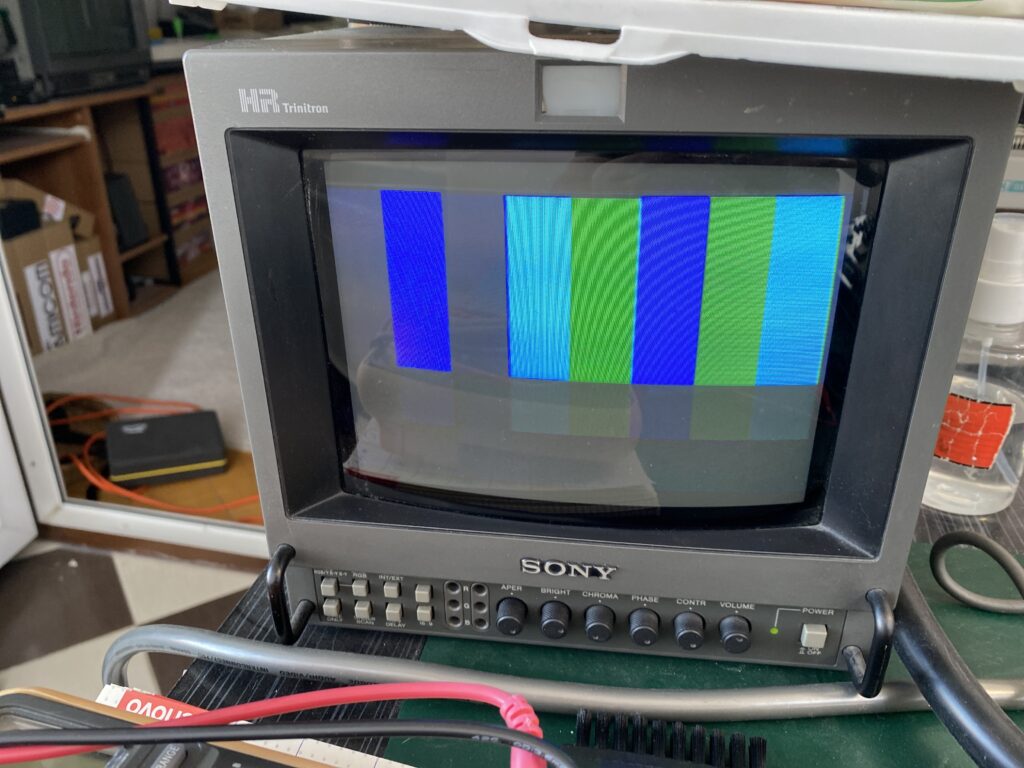
Now when testing the board … everything is worse. Now, in addition to the old problems, there is now a problem with the color Red. As you can see in this video, all of the colors appear in the narrow columns on the left and right, but there is no Red on the main screen in the middle.
I decide to put the board into TEST mode to test the red color. For this, press 1P A+B on the RAM ROM TEST screen. Then, on the menu, select Screen test.
As you can see in the Screen Test, there is no trace of Red.
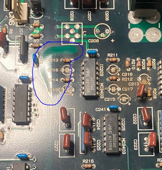
In case I missed something, I check around further with the Logic Probe, and I find another IC on the same line.
Pin 18 of IC10 is connected to the same pin as the others – I missed it before.
There are 3 resistor packs in this area. I measure the resistance of their feet with my multimeter – they should be equal to each other.
The results are good.
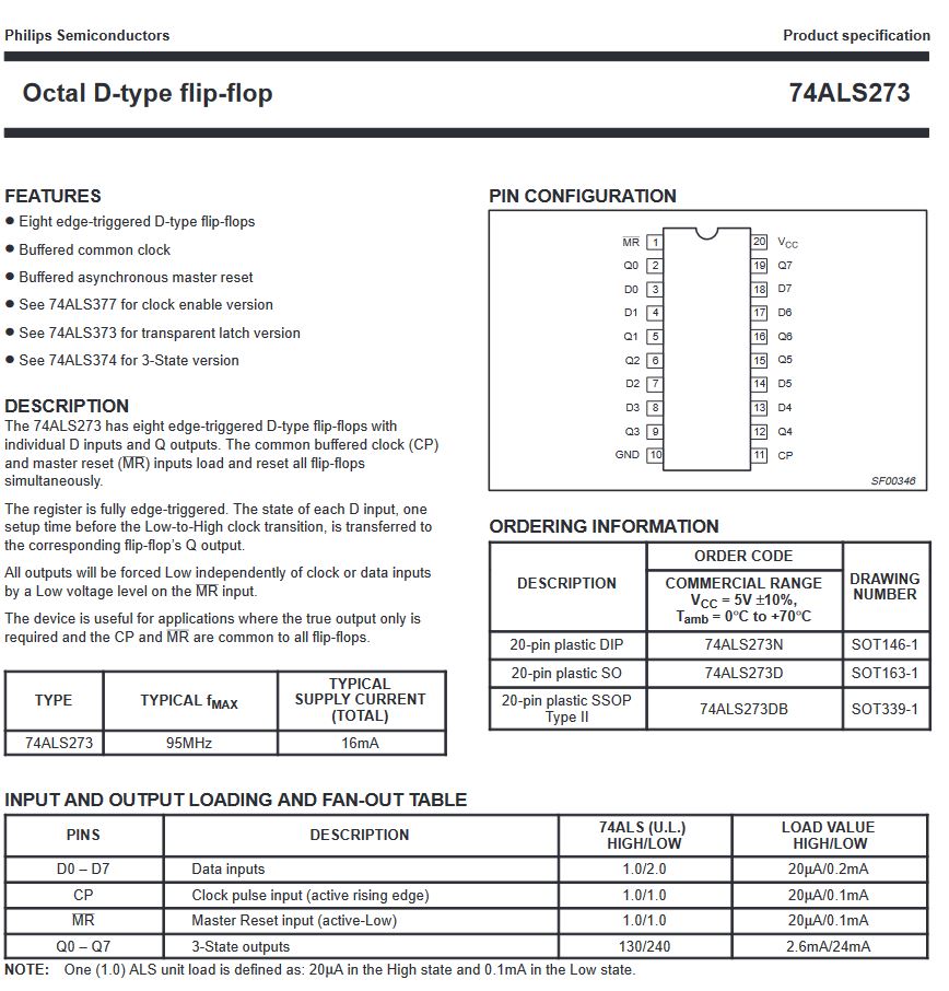
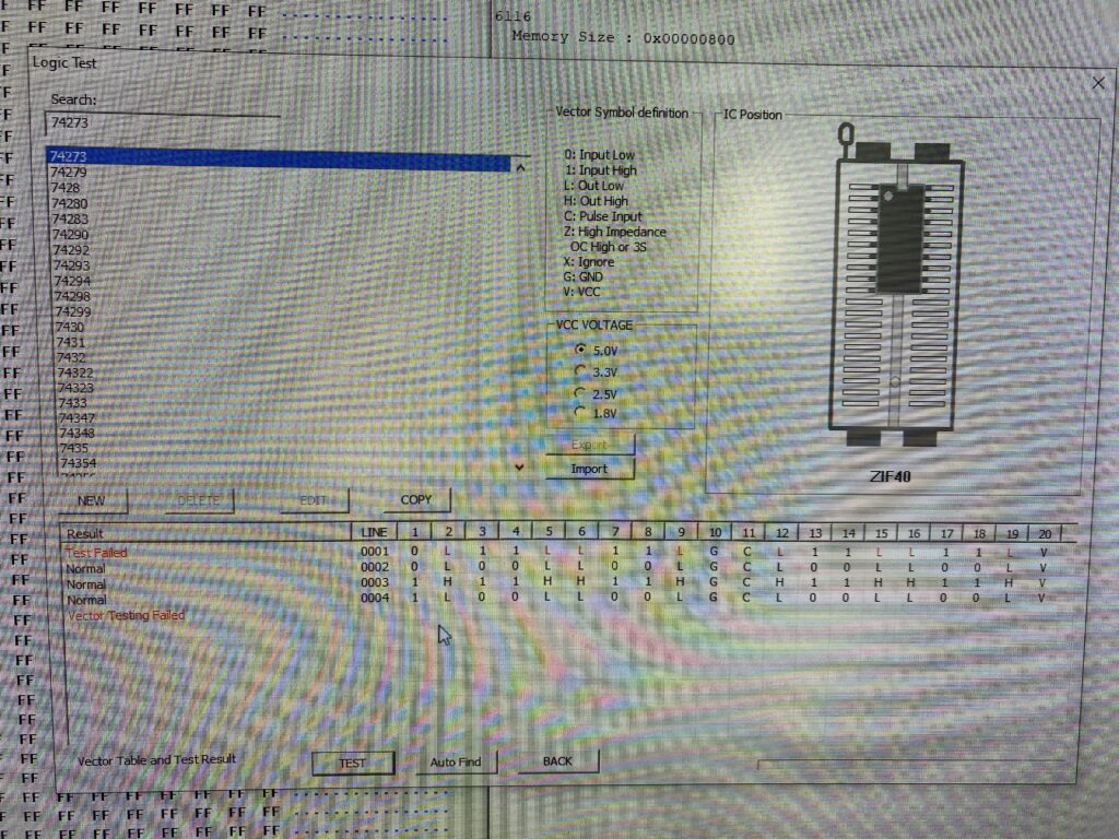
IC10 is a SN74ALS273N. According to the data sheet for this part, Pin 18 –> D7 (Input)
Here is my drawing of the connections between these chips:
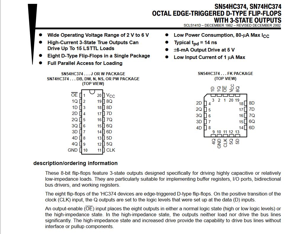
I’m thinking of replacing IC10, and then something strange catches my eye. On the chip it says SN74ALS273N but on the motherboard, HC374 is printed as the part for this chip. At first, I think that the wrong chip was installed in this board, but then I look at other photos of this board on the PLD Archive site and they are the same.
I do some research on the subject and the information I can get is that 74HC374 was used here because 74LS273 was too slow. Later, when faster 74ALS273 parts came out, they switched to them since they were cheaper.
I proceed with replacing this IC. Since I don’t have another 74ALS273 on hand, I will replace it with a 74HC374.
After removing the old part, I test it out of circuit in my EPROM programmer and I see that its problematic.
When the game now, it seems that there is a big improvement. The colors that were flickering in the background as the character walks have been fixed.
But we still don’t have red…there is only red on the far right of the screen.
You can see it better in this video:
Let’s keep on trying. When checking the data sheets further, it seems that the pinout of this new 74HC374 IC is slightly different than the 74ALS273 it replaced.
SN74HC374N –> Pin 18 –> 8D (Input)
It turns out that on the 74ALS273 datasheet, the channels are numbered from 0 to 7. On the 74HC374 datasheet, the channels are numbered 1 through 8. However, the functionality between the two is the same.
I decide to remove the other 74ALS273 IC above the one I just replaced – IC9 – and test it.
No problems in the test, but I proceed to replace it with a SN74HC374N to match IC10.
Now when powering up the board … everything works correctly. The board is saved!!!
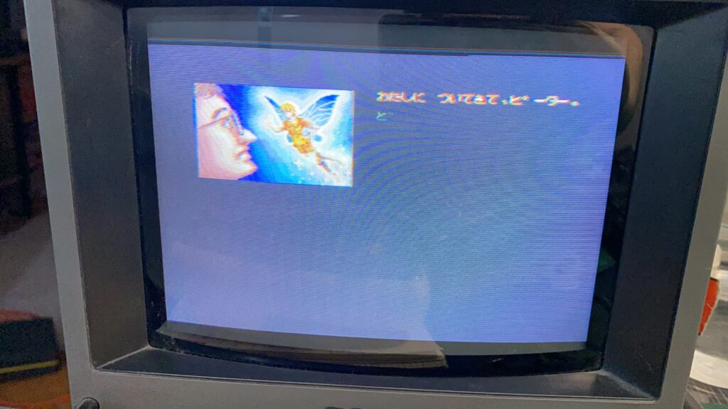
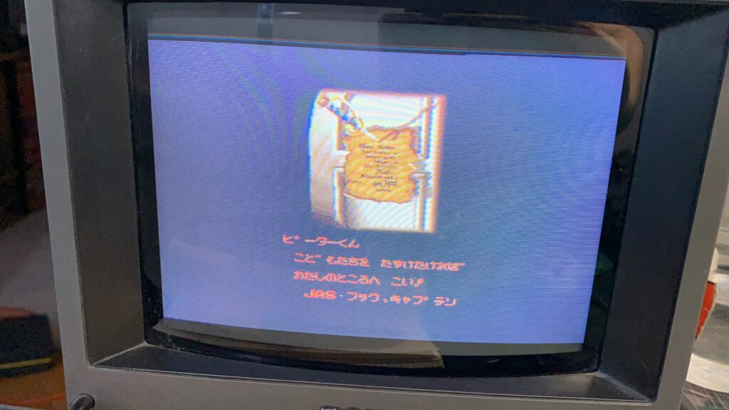
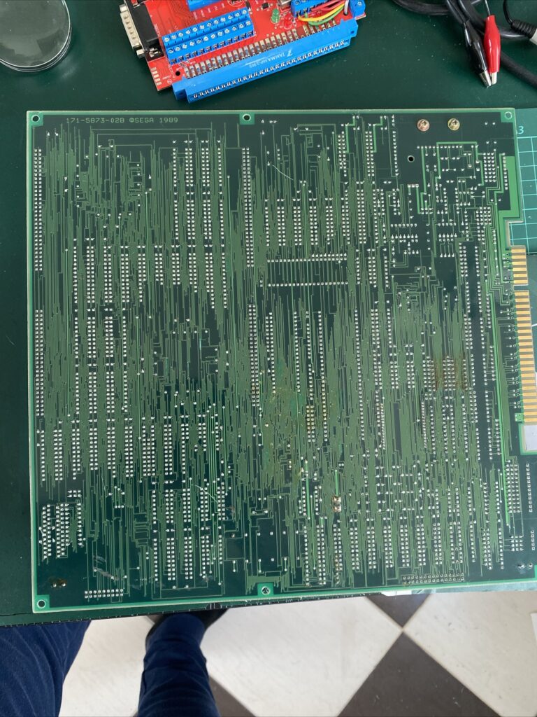
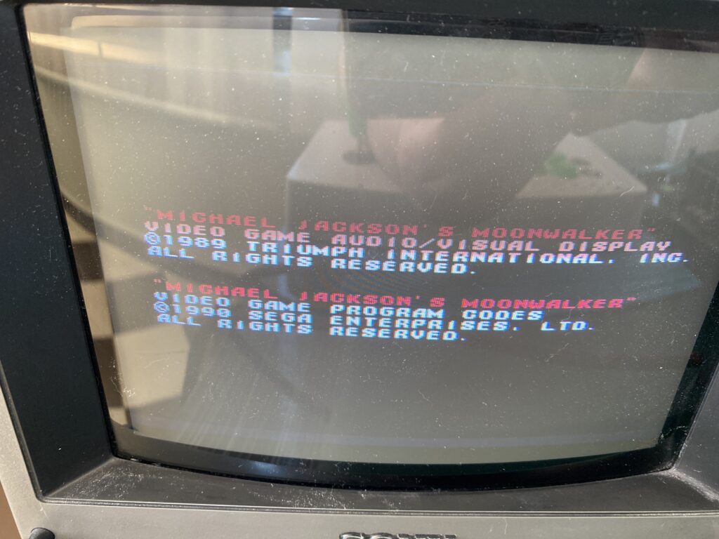
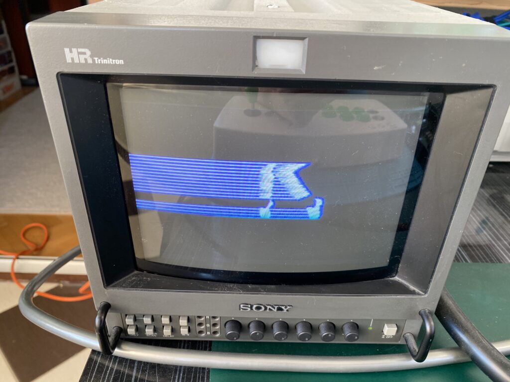
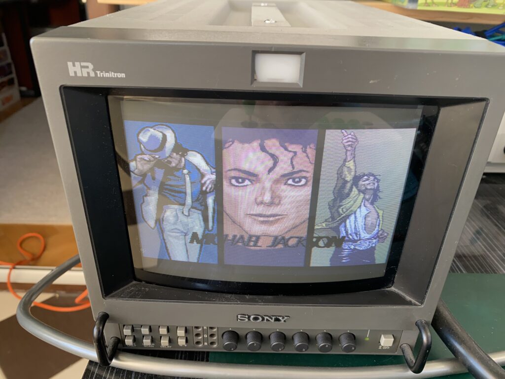
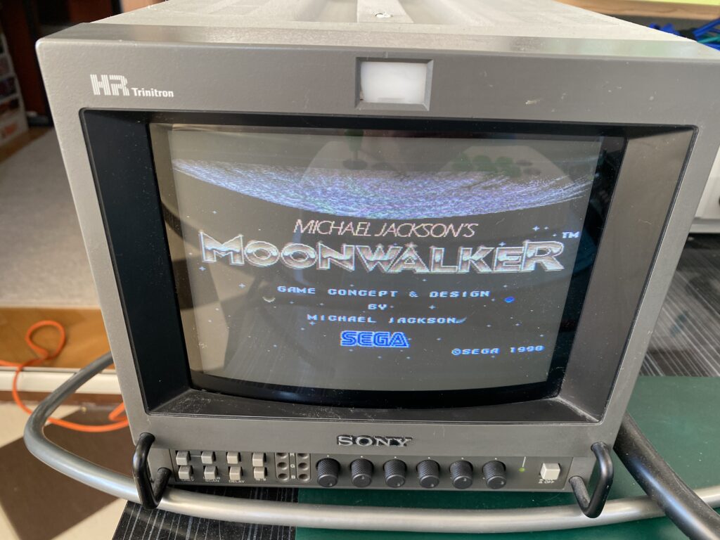
Hello everyone, this time I have Moonwalker – perhaps my favorite game – on my desk.
I bought this board “as working” but when powering up, I found out that the board doesn’t boot – it shows no activity at all..
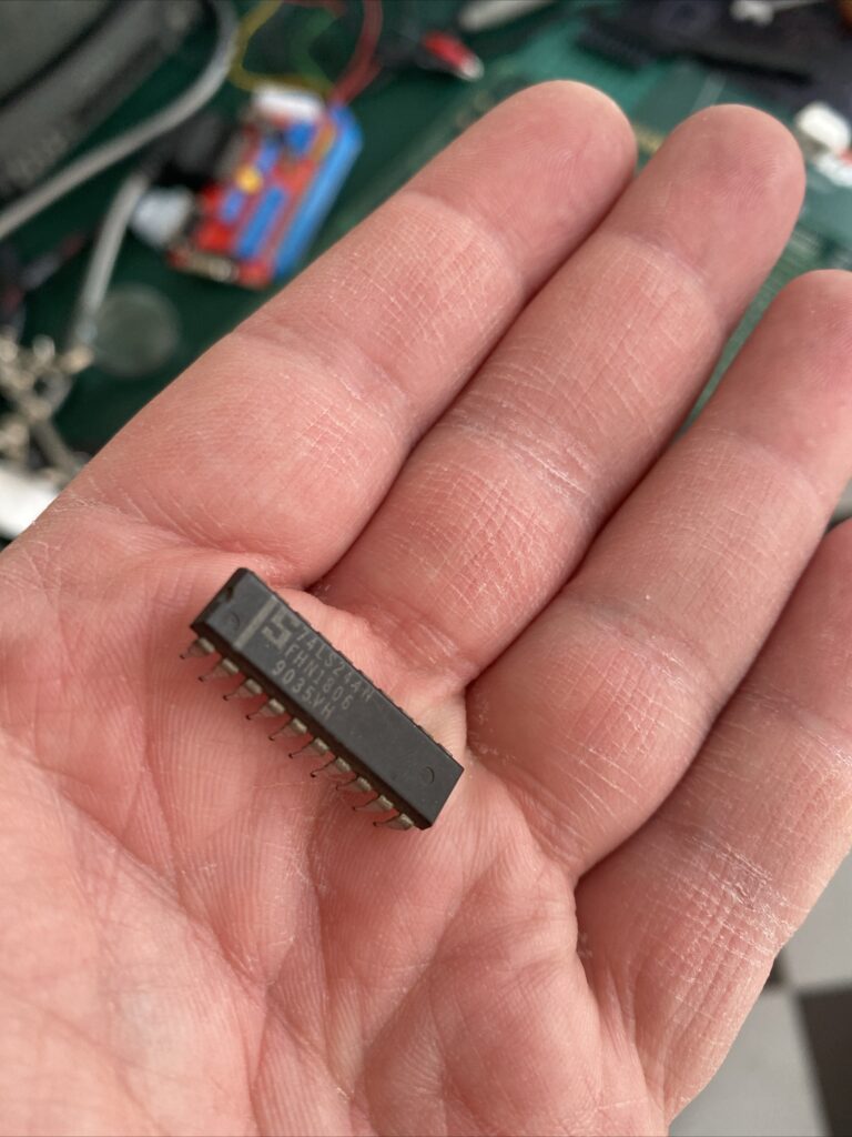
And an IC fell out of the shipping box. But the funny thing is that there is no missing IC on the board.
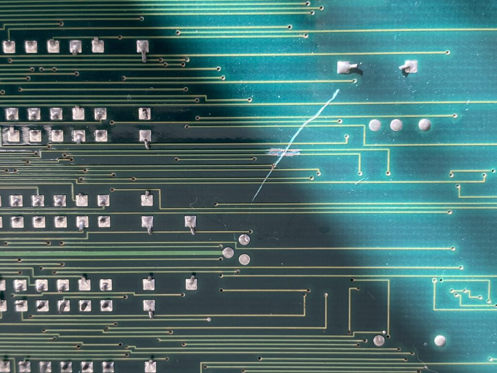
I bought this board as “working”, but since I bought several boards together and did a package consolidation before shipping, the seller packed these boards naked back-to-back and this is the view…
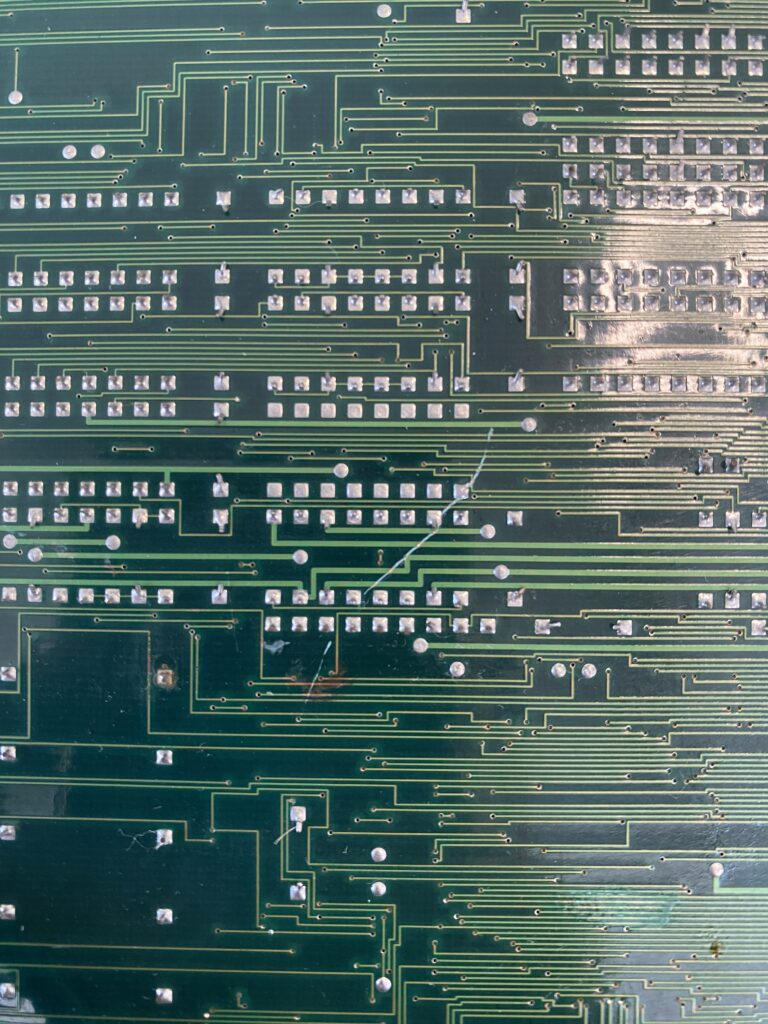
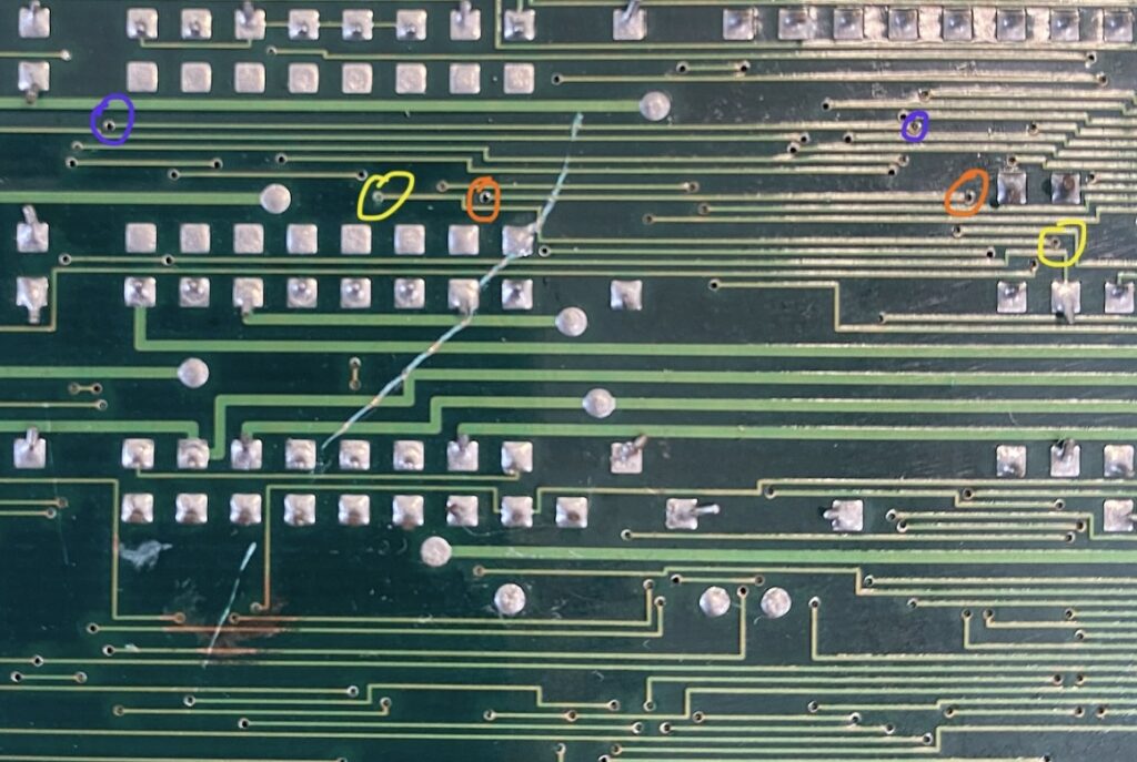
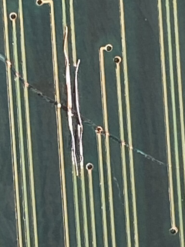
When we look closely, we can see the damaged traces.
I took out my multimeter, and with it set for continuity testing, I measure the two ends of each trace where a deep scratch passes over it. Fortunately, not every trace is damaged.
There are 2 broken traces at the first scratch location.
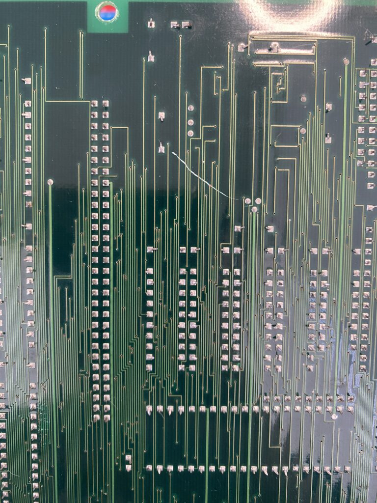
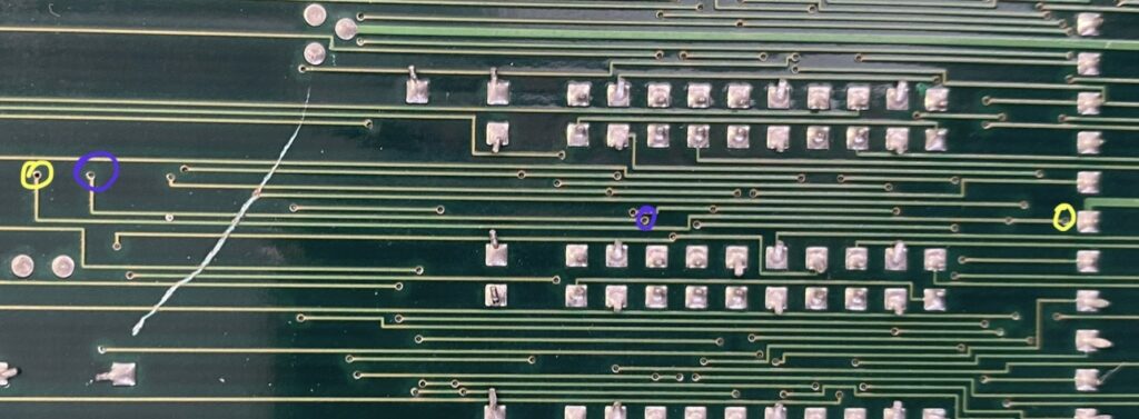
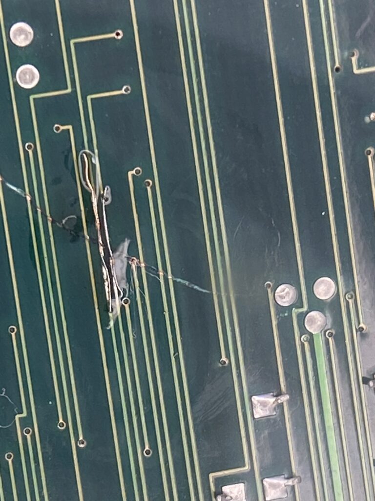
In the second scratched place, we have 3 damaged traces. Moreover, it is a bit more of a winding road.
We’re preparing the operating room now.
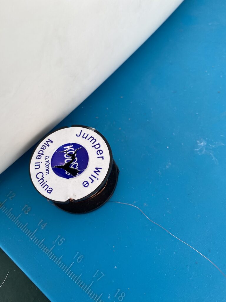
In many articles, it is written that “kynar wire” should be used for trace repairs. I couldn’t get it from abroad under this name. This is the wire I found – it is 0.10mm.
If you have any feedback such as this is not suitable, too thin, etc., feel free to say so.
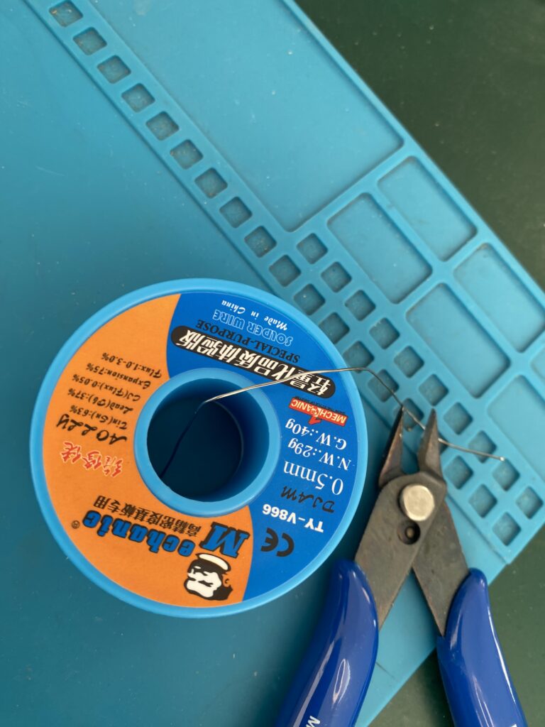
What else do you need? Solder:
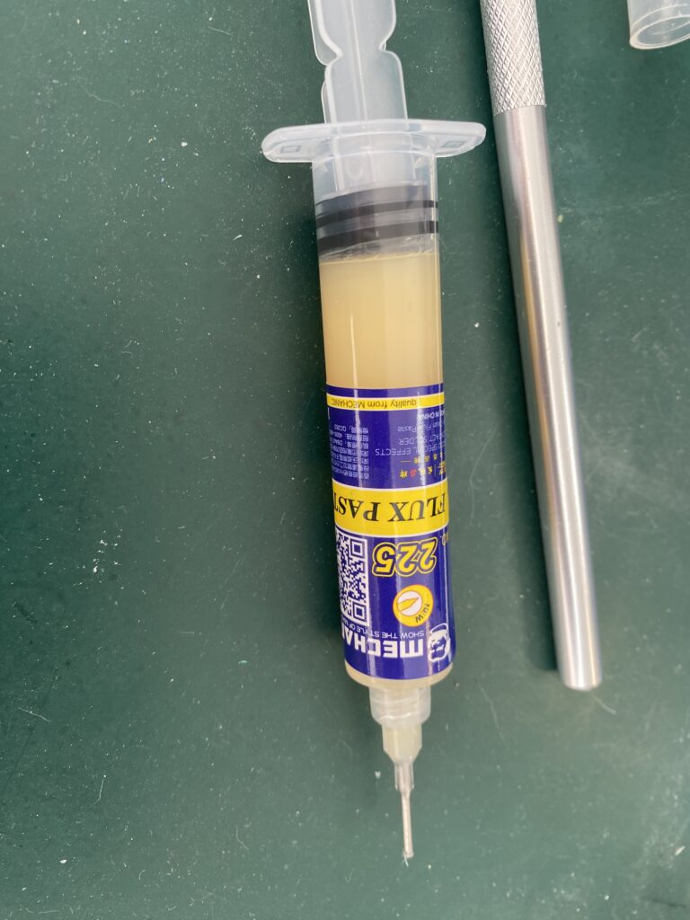
What else do you need? Flux:
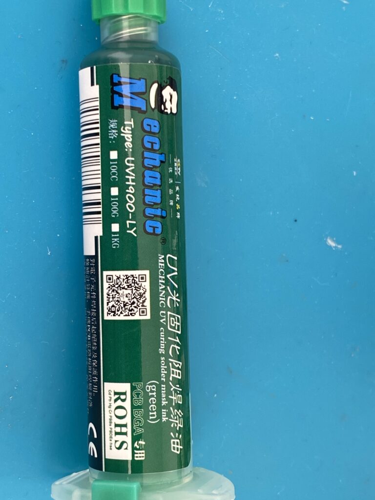
What else do you need? UV solder mask ink. Some people uses nail polish here, but I prefer to use the professional solution for the problem.
And last but not least, what else do you need? A good eye or a lens or a microscope.
And what’s the last thing you need? Patience like a saint.
First of all, we dig up scratch off the masking a little on the left and right where the trace is broken (enough to expose the copper).
Then add a little flux on top:
Then we solder in a small length of jumper wire to bridge the gap.
How is this procedure done by the masters?
First you apply heat with solder and flux to the bridging wire. Then you apply flux and solder to each end of the broken trace. Then you solder one end of the bridging wire to the left side of the broken trace. Then you solder the other end of the bridging wire to the right side of the broken trace, but while doing this, place something that conducts heat (like a cold solder iron tip) in between so that the heat on the right side does not reach the left side and melt the solder there.
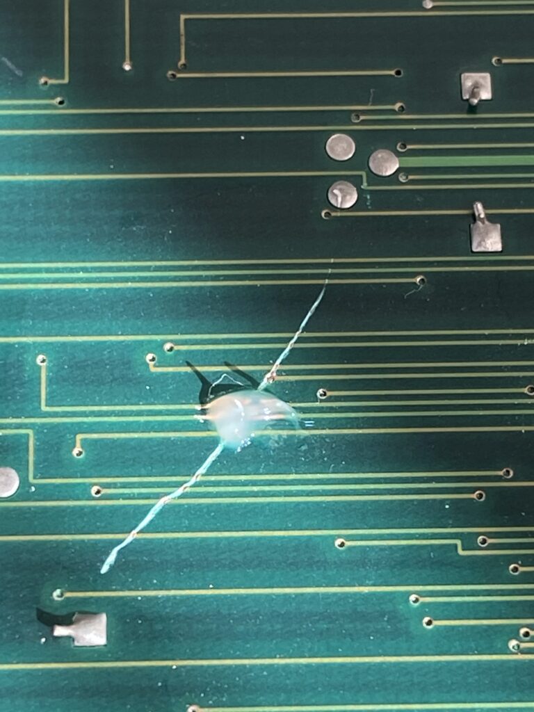
Here’s how it looks after soldering:
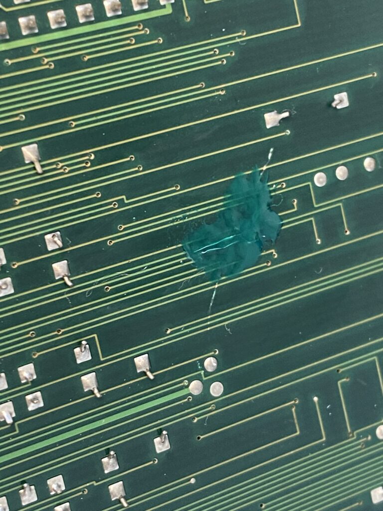
I apply solder mask ink on top of it to prevent future damages.
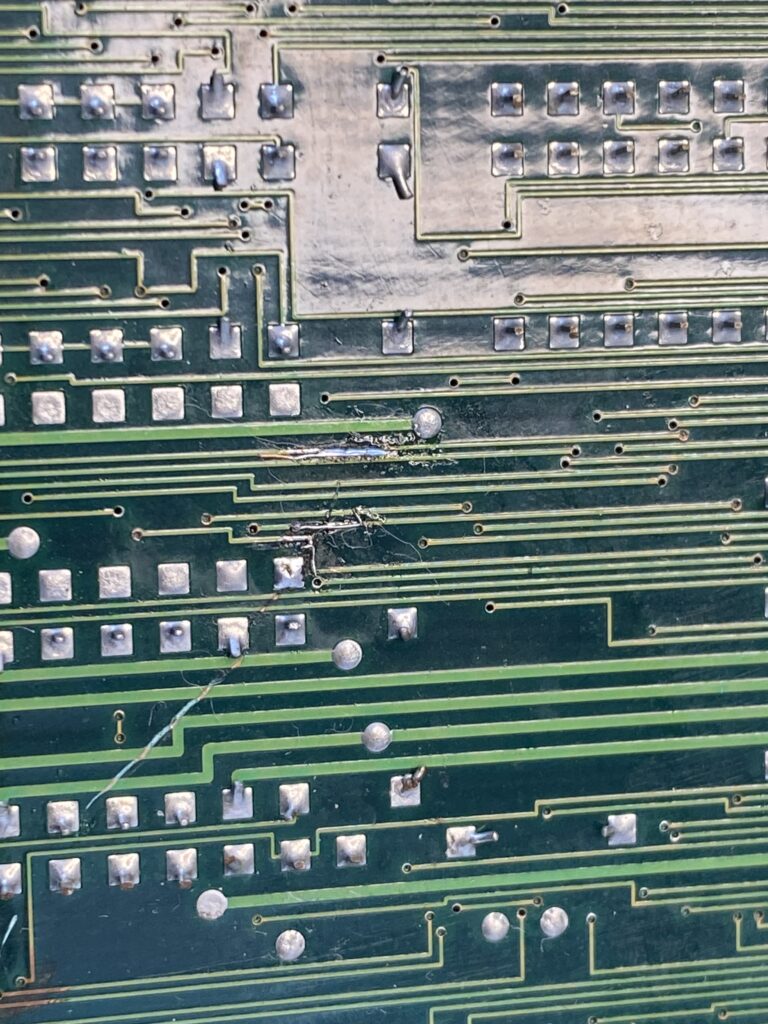
Let’s move on to the second damaged area.
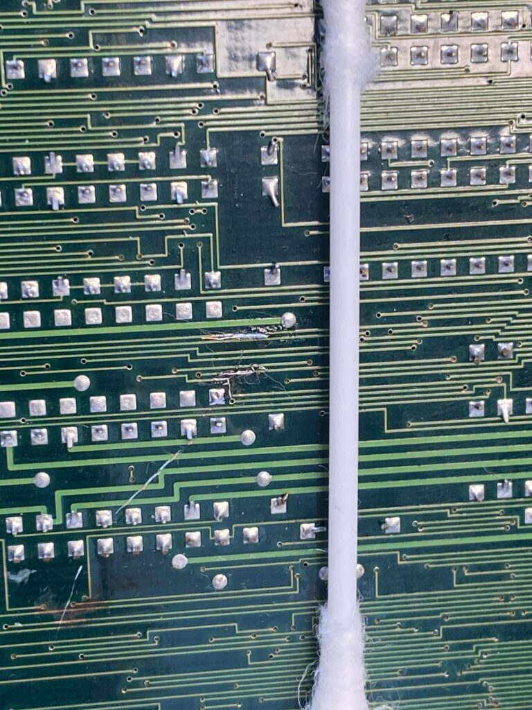
This place made me sweat a lot – especially the curved path in the middle – but I still managed it in the 10-15th attempt without giving up. I am not patient but I am stubborn.
I put an cotton swab next to it so you can see the size of the area I’m working in.
After the repair, we apply solder mask ink to it too.
Time to power up and see how things look. Recall that this was sold to me as a working board, but the photos taken before it shipped to me didn’t have this damage.
I power it up and there’s still no activity – just a black screen.
Then I remember something – an IC fell out of the package…
When I asked the seller about this IC, the seller said that it must have been mixed up while packing the board and that it had absolutely nothing to do with this game…
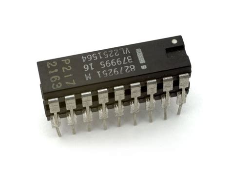
I immediately remove the ROM daughterboard and look underneath. And here I see that two of the ICs have been piggybacked. I didn’t photograph this (sorry), but here’s a generic example:
Piggybacking can be useful while diagnosing a board but is not a recommended long-term solution. It will damage other components because the piggybacked chip doubles the power draw for that circuit.
The type of IC that fell out of the bag 74LS244N. Next to the two ICs that are already piggybacked, there is another IC that is not piggybacked. Guess what it is? A 74LS244N. I’ll piggyback this IC onto it see what will happen…