
Some weeks ago I was sent a Mega-tech board to look at with an apparently common fault. The PCB would not see any cartridges that may have been present.
As it is considered a common fault I thought it best I draw some schematics up in order to allow others to hopefully fix their own fault. What I found with this system was far from easy.
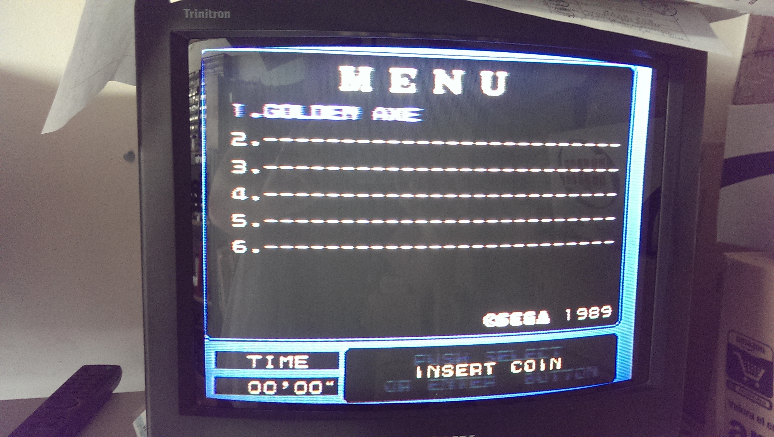
NOTE: I use a variety of different displays throughout this repair and my test bench TV displayed the colours a bit wrong but its not a PCB fault.
The visual inspection turned up something straight away on the underside around one of the factory fitted wires.
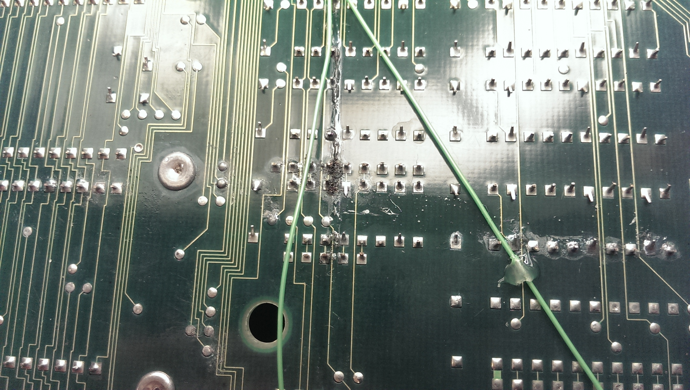
I cleaned this up and tested the board. It fired up OK but I could hear a strange ‘fizzing’ sound and occasionally a ‘pop’. As luck would have it I was in a darkened room at the time and I could clearly see that resistor array RA18 next to IC37 was glowing. This was located right underneath where the burnt out wire was.
I replaced the resistor array and did some continuity checks and everything was good.
I think at some point the wire had been pierced by an IC leg and shorted out. Maybe this is something for owners to check out?
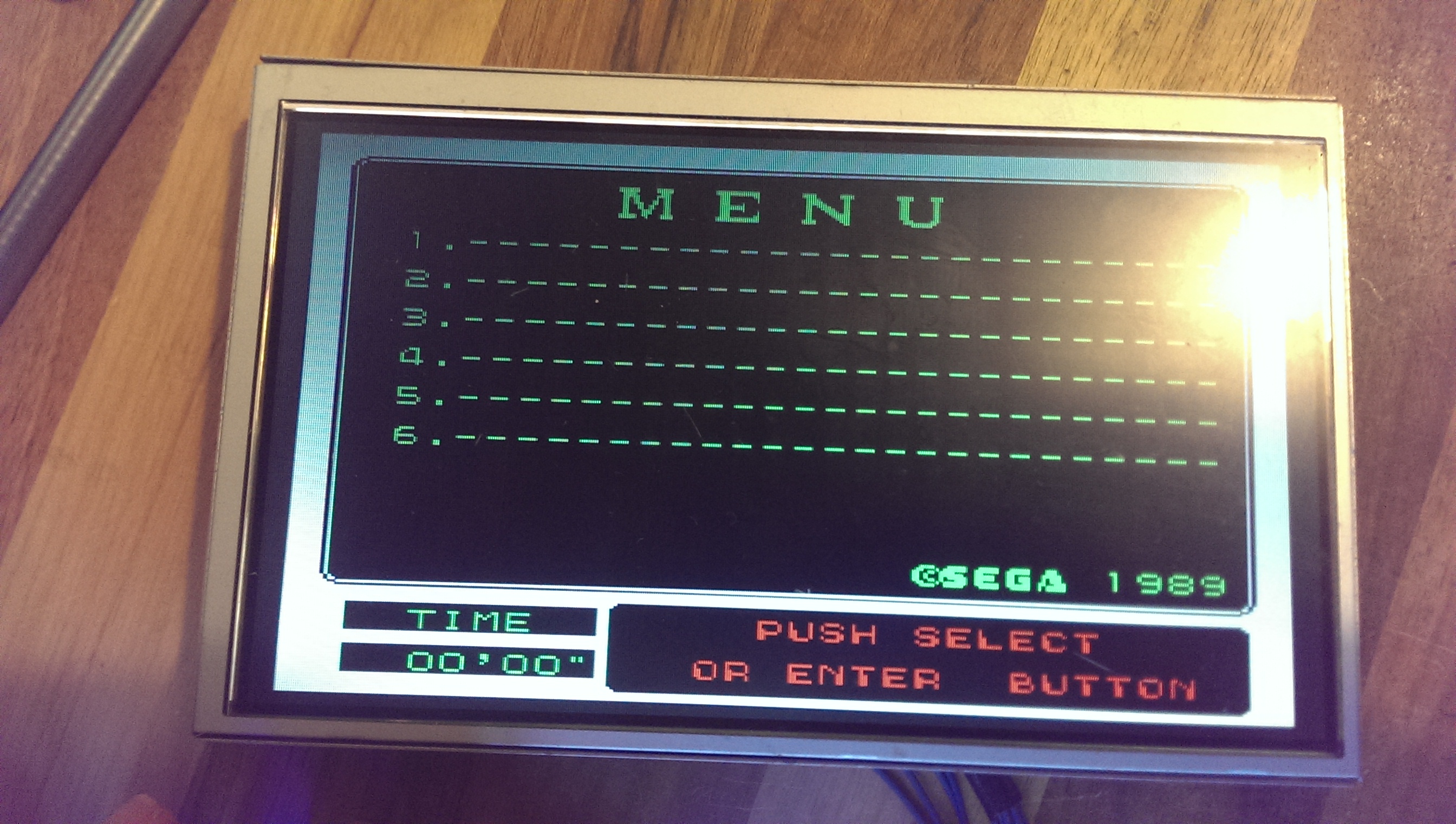
This is what I got booting up
The menu has its own Z80 processor and BIOS so I thought this would be a good place to start.
The first step was to take the code apart and see exactly what it does to read the cartridge ports.
Ultimately the Z80 sees the cartridges between address &8001 – $9fff, but before we can do that we have to jump through a whole set of hoops to setup the system. It is here I found my first problem.
I used the Fluke 9010 heavily throughout this repair so I had full control of this setup.
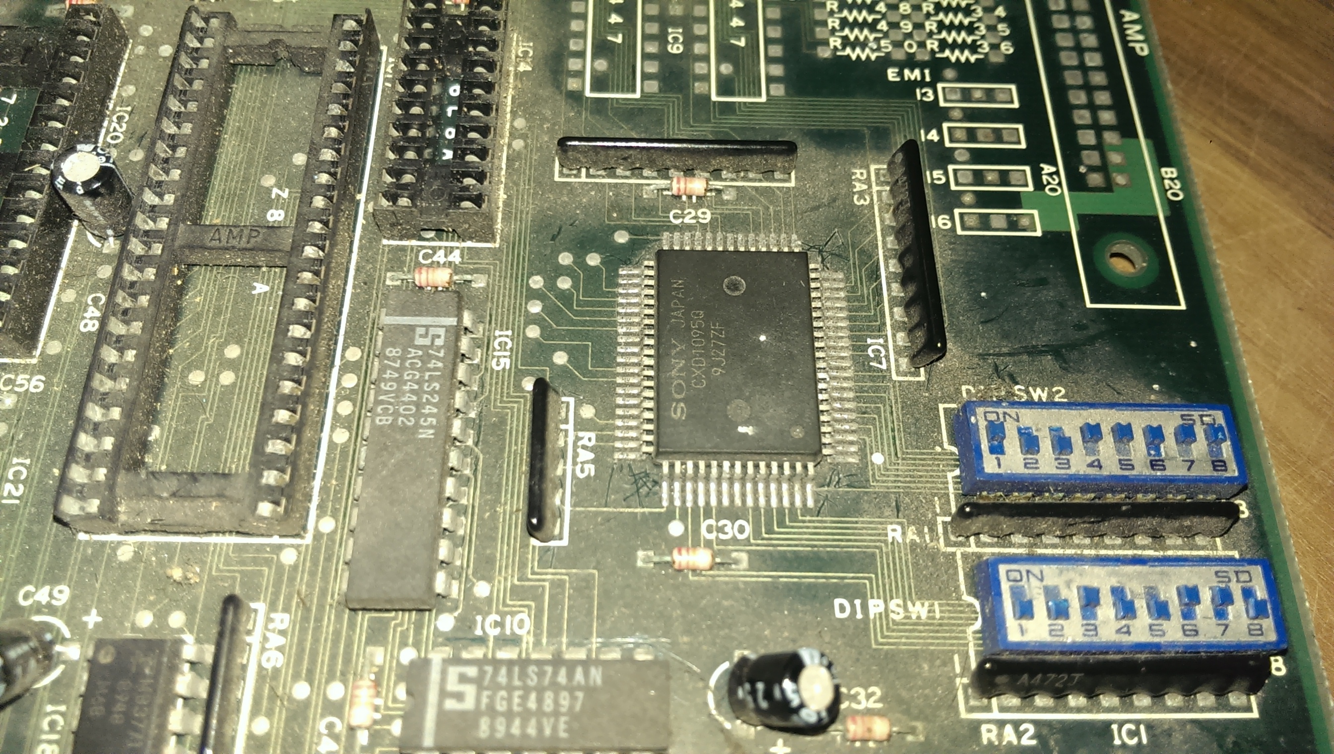
On this board there are a couple of CXD1095Q I/O extender chips. These chips require setting up before they can be used and the BIOS does this on startup.
They have 5 ports (A to E) and the pins on each port can be set as either an input or an output. To set these up the BIOS writes the necessary values to the registers of the CXD1095 at address $6406 and $6407.
My focus originally started on the one at IC7.
So ports A and B are not used on this chip so they are set as inputs.
Ports C, D and E are set as outputs.
Port C lies at address $6402
Port D lies at address $6403
Port E lies at address $6404
Reading at address $6c00 clears the /RESET line to IC7. This needs to be done before the chip operates.
The port I was most interested in at this stage was port E as this is the one that selects cartridge slot to be used.
To setup port E I simply had to write the value 0x0 to address $6407 and then whatever I write to address $6404 should appear on pins 49, 50, 52 & 53.
This was not what I had though, instead all my pics were dead.
After convincing myself this chip really was bad I hit the internet and ordered a couple of replacements from China.
A week or so later and I had these replacements.
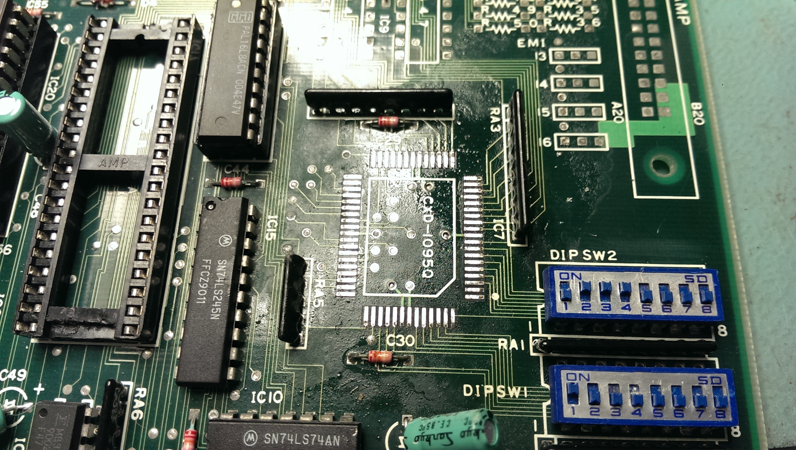
I removed IC7 and fitted a new one.
Now when I ran the same tests I got correct activity on the output pins but the board still did not see any cartridges.
Moving on from here brought me to the second CXD1095Q chip at IC24.
The registers lie at address $6806 and $6807 on this chip.
This chip is responsible for reading various signals back including the “Cartridge Present” signal.
Address $6802 is the cartridge present signals and following the same testing as before I should have been able to write 0x3f to $6806 and then be able to read back values at address $6802. Again this was not the case so I removed and replaced this chip which gave me back all my signals. Like before this did not cure the problem.
The advantage I had now was I could setup the board so I could read the cartridge starting at address $8001. When I tried to read I got slightly different results each time, kind of like if one or two of the pins were floating. None of the pins were floating however.
As the Z80 is an 8 bit CPU and we are reading from a 16 bit bus there needed to be some other logic in the way. This takes the form of a custom chip marked 315-5309 at IC66.
Using MAME I knew what values I should have been reading back from each cartridge and I could confirm these readings using a logic probe on IC53. I could infact confirm the signals from the cartridge right back at the 315-5309 chip but the signals coming out of the chip back to the Z80 were different on each read.
I already had access to a spare 315-5309 so I took the plunge and replaced it. To my surprise it worked!
On paper (or screen) this appears to be a fairly straight forward fix but I assure you I was pulling my hair out for most of it.
A huge thanks to Charles MacDonald for all his assistance and providing me with a proper datasheet for the CXD-1095Q chip.
Sorry, the comment form is closed at this time.