
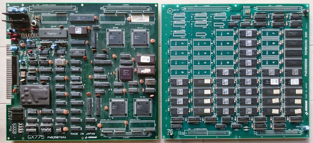
A friend asked me if I could take a look at his dead Super Contra PCB which was a 2 boards version (the same game exist in a single board version where all the small mask ROMs on the sub board are replaced by bigger mask ROMs on the main board).
All I got was a black screen with no sound. Checking with a scope around the CPU area revealed there was almost no activity. The CPU is a Konami custom 052001, hard to troubleshoot as I couldn’t find its pinout online.
While checking for possible loose connections on some chips. I found that bending a bit this small chip near the JAMMA connector (an electromagnetic interference filter) was booting the game:
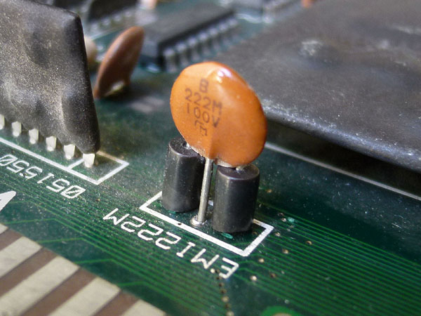
It was a bit loose. I desoldered it and found one of its legs broken. This was hidden behind one of these two small black ferrites. I repaired the leg and resoldered it.
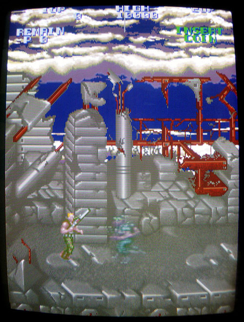
Well, the game was now booting but graphics were a bit messy:
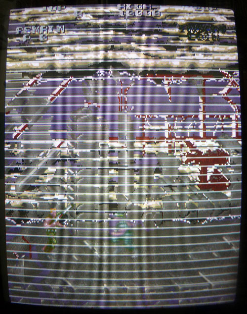
ROMs containing graphics and voices are located on the sub board.
I started checking this part as it has a pretty simple layout (basically mask ROMs with buffers) and noticed 3 mask ROMs with corrupted signals on their data lines. These 3 ROMs were all connected on the same bus to pins 2 to 9 (A bus) of a 74LS245 buffer @ location D1:
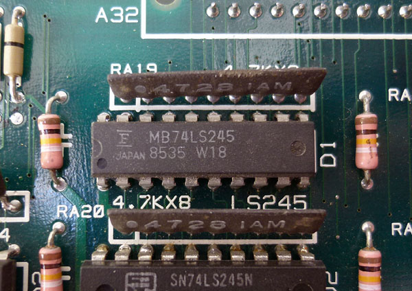
There are several other 74LS245 chips connected to other mask ROMs on the board and they all seemed to have “normal” activity signals. The B bus of the suspected chip (pins 11 to 18) seemed inactive and was connected to a custom chip on the main board.
I first tried piggybacking that 74LS245 @ D1 but nothing happened. The lines were still looking the same with garbage signal on bus A side, which could be caused by the possibly faulty chip itself. I desoldered it and it was tested bad on my IC programmer. I put a new one in place and the problem was resolved:
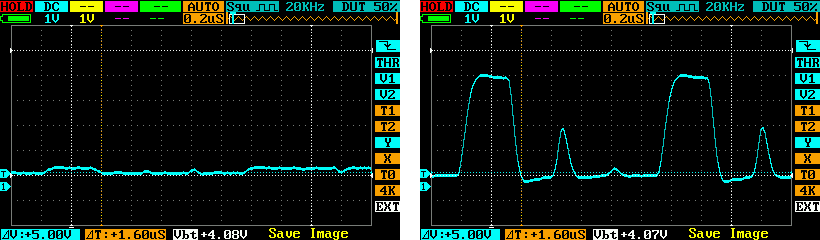
Here is what every signal on the A bus (pins 2 to 9) of the 74LS245 chip looked like with the faulty chip (left) then with a new chip in place (right). You can clearly see how bad the signal looked like on the left:
2 Responses to “Super Contra repair log #2”
Sorry, the comment form is closed at this time.
Good job.Pardon, which is the model of your digital scope?
Thanks mate. It is the DS203 Nano Mini DSO. Affordable and handy, I’m pretty satisfied with it.
Anyway, it has a limited bandwidth (hard to get something at higher frequencies than 20 MHz) but I think it is sufficient for most of PCB repairs.