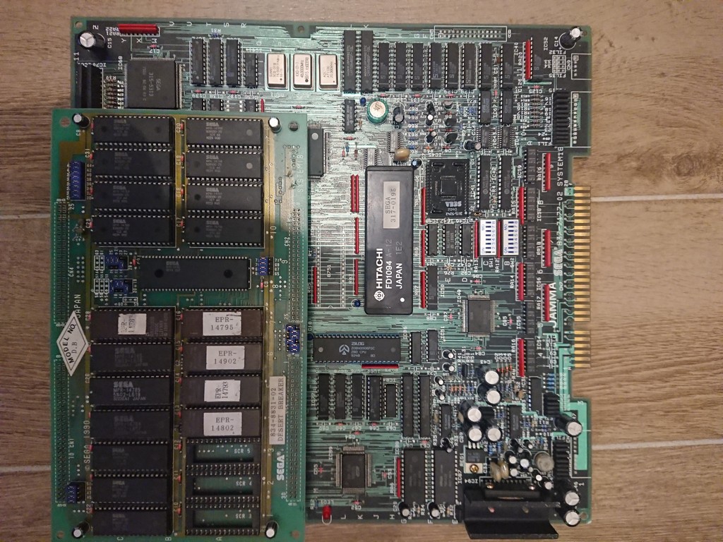
Bought a cheap Desert Breaker for my collection which the seller declared as having no sound.
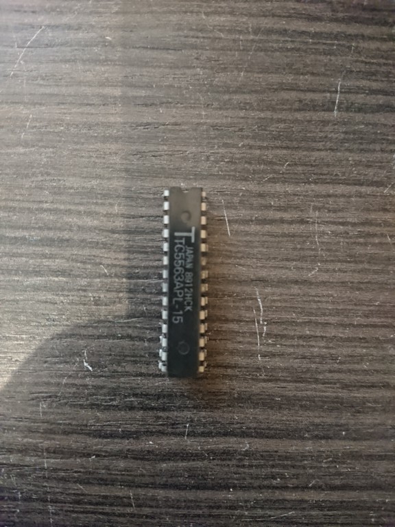
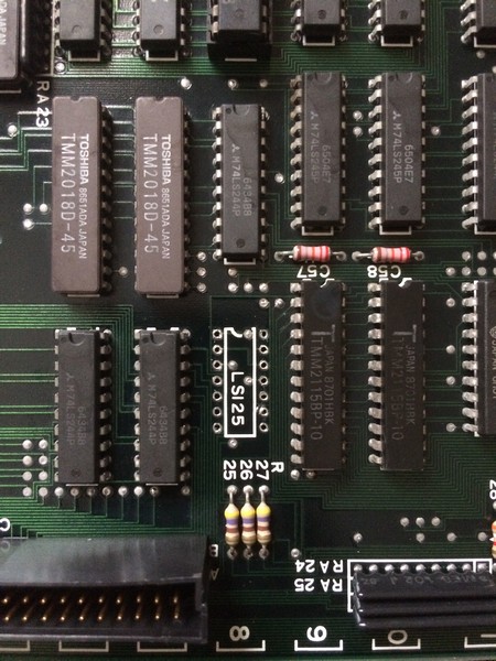
This game is running on system18 hardware. Since the sound was totally missing I first tested the z80 which was good and then I desoldered the SRAM which was
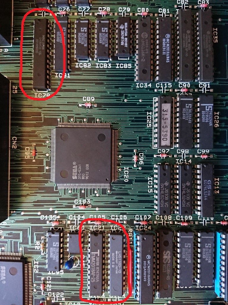
a Toshiba @IC79 , normally very unreliable in comparison to other makers and infact it was faulty.
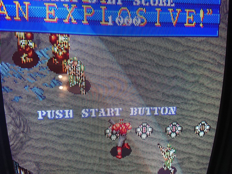
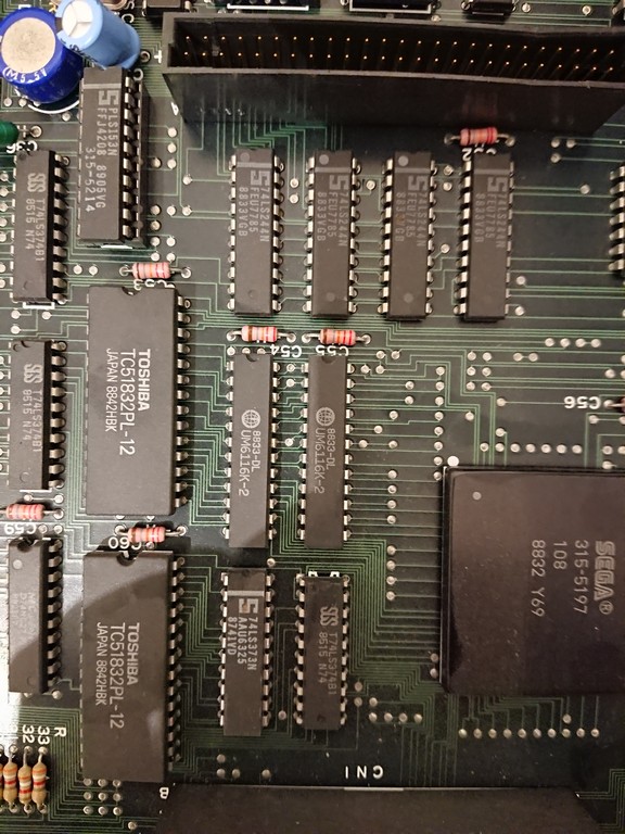
It fixed the sound but playing I noticed that some sprites had missing lines
This problem could be either the custom chip 315-5361 ( sprite generator ) or the srams connected to it ( IC21 and 22)
Since all the address line were good, I proceeded to desolder and test the srams which were infact bad bad.
Some weeks ago I bought this game for my collection in really great conditions.
While playing, I messed up with the external potentiometer of my supergun and menaged to detach it for a brief moment . Result was that the power supply jumped to 7V on the 5V line and 18V on the 12V line.
With my surprise, the game was not totally fried, sprites were still good but all the background was totally black
Also the game had no sound ( but the amplifier was still good)
For the graphics problem, 2k sram @H15 and H16 had all the data lines in the grey area.
Changing them restored completely the graphics.
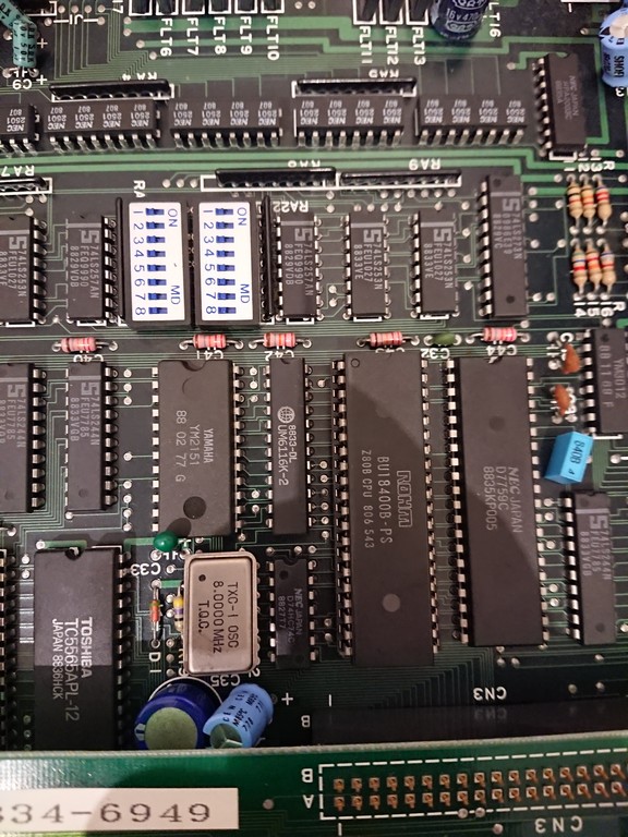
The sound had also another UMC 6116 sram and the data lines were completely in the grey area.
Changing it led to no improvement but after checking the connections I found out D6 line was not connected to the Z80 but only to the YM2151.
I probably broken it during the exhange. Restoring the line led to a fully working game.
In the end it appears that UMC parts were the weakest devices of the pcb , I replaced all the ones which were present on the pcb
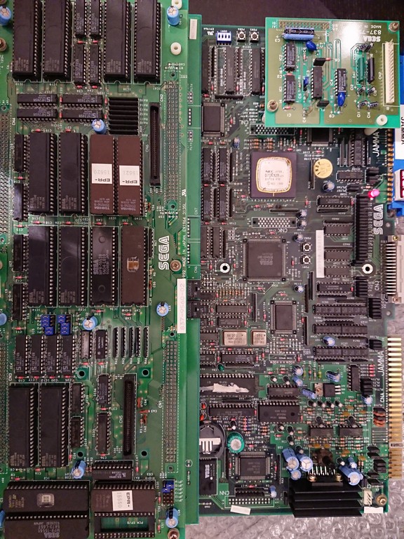
Got this game from a friend who took out the board out of a rusty cabinet.
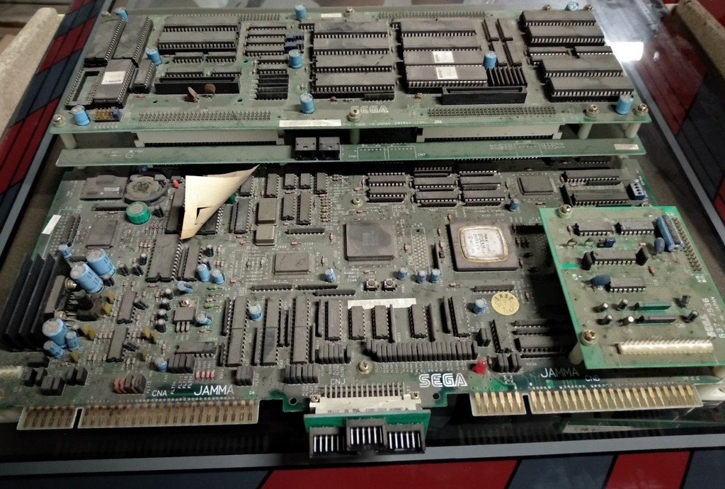
The game needed badly a clean, so I dismounted everything before attempting to turn it on and washed everything carefully.
The game has two jamma connectors for player 1 ( Monitor A,left connector looking at the above picture) and player 2 ( Monitor B, right connector looking at the above picture). The connectors share same power lines, so you can connect wherever you want to play as P1 or P2.
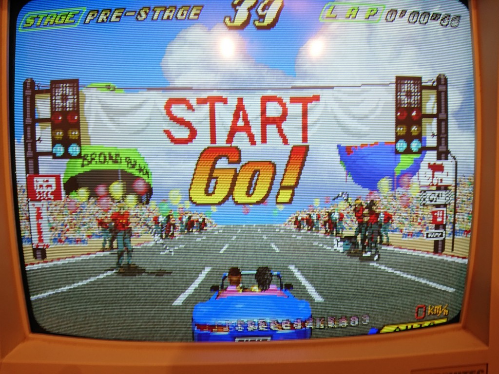
Unfortunately board was not working correctly, it showed from a brief moment a garbled text about network connection and then nothing happened.
I decided to start dumping the program maskroms and found immediately one branded SEGA MPR-15539 which had some internal connection problems.
The other one , same type and capacity was dumped good.
After burning a new program rom on a 27c400 ( 4mbit maskrom pinout eprom), game booted perfectly although without any sound.
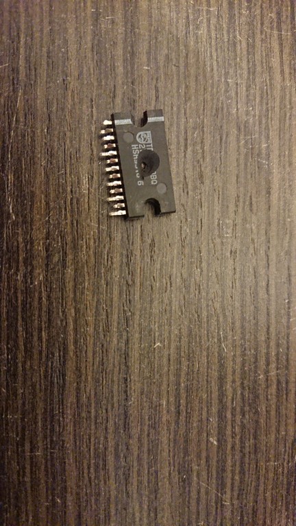
There was not even a noise coming from amplifier so I decided to desolder it and found immediately the problem
The amplifier was litterally blown
From Mame source I could get the right one to order, a TDA1518AQ, replaced it and finally the game had sound.
Unfortunately some tracks sounded bad with wrong samples.
There were other SEGA branded maskroms used as PCM samples, I read both of them ( 16mbit maskroms) and one of them , IC1, had A16 internally broken.
After buring a new 27c160 eprom with IC1 data, game sounded perfectly again.
No other problems were found
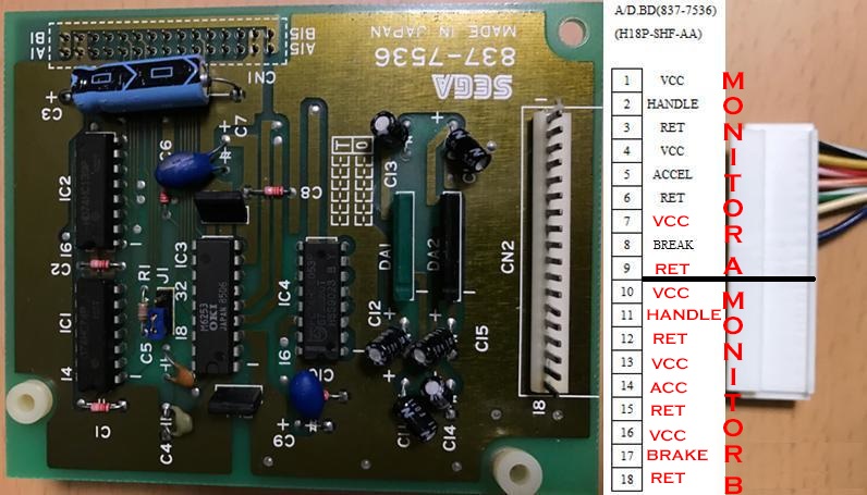
I will share the pinout of the board to play it on a different cabinet than the original one with a filter board ( the manual has only the schematics of the filter board unfortunately).
Game is Jamma as stated, so all power, video and audio pins are the same.
Board is using the following digital pins: on component side pin 22 is for shift up and pin 22 for shift down. On solder side, pin 22 is to select DJ Music or radio, pin 22 and pin 23 to move forward or backward the selection of musics. This is valid for both P1 and P2 connectors
There is an AMP connector in the middle used to drive lamps but I haven’t yet figured out the pinout and to me is not very interesting.
The most interesting part is the analogue controls which is handled but the daughter board 837-7636 which is in common with all Sega System 32 driving games.
I found a partial pinout on a japanese website and decided to expand it with Outrunner pinout
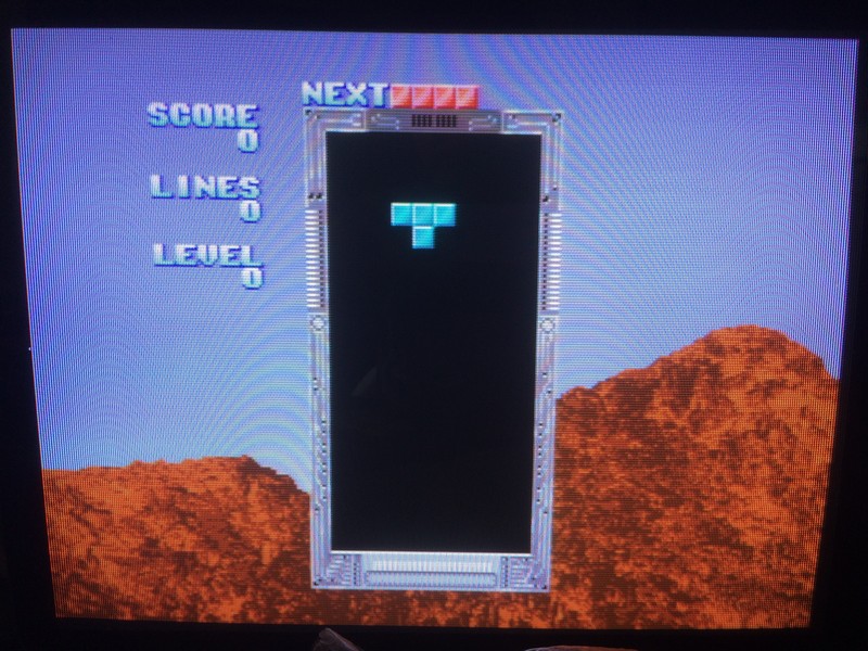
I received this system 16 motherboard from an arcadeitalia member called Consoleman.
The motherboard was missing completely the sound and didn’t sync with the monitor.
After checking with my sound probe that the sound was really missing by probing the pre amps, I started to check the Z80 which was confirmed good and RAM which was faulty.
Changing the ram restored the sound completely.
The Sync problem was not easy to check because the TTL which outputs the signal to the finger board is under the romboard.
In anycase I managed to test it from the solder side and I noticed the composite signal was about 14khz, that is why was not syncing.
I proceeded to desolder it
and tested out of circuit with my programmer as good….
Instead of soldering the same part, I decided to find another 74Ls125 among my junk boards.
It was not common but in the end I found it on another board and soldered it.
Motherboard was 100% fixed.
Probably my programmer hadn’t enough sensibility to declare the part as bad. First time it happens.
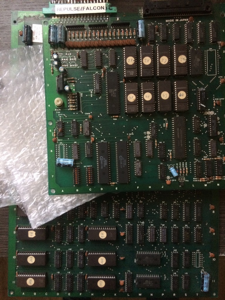
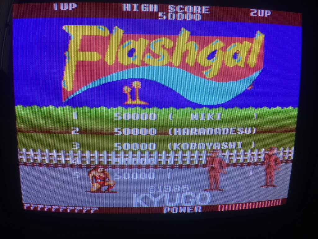
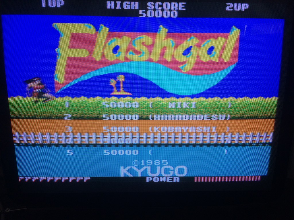
I bought this game for my collection declared perfectly working.
Flashgal runs on the very same pcb of other two games developed by Kyugo which are 99 Last War and Legend.
On the bottom pcb it is silkscreened CVG-48C which is very similar to the codes used by ORCA on their hardware
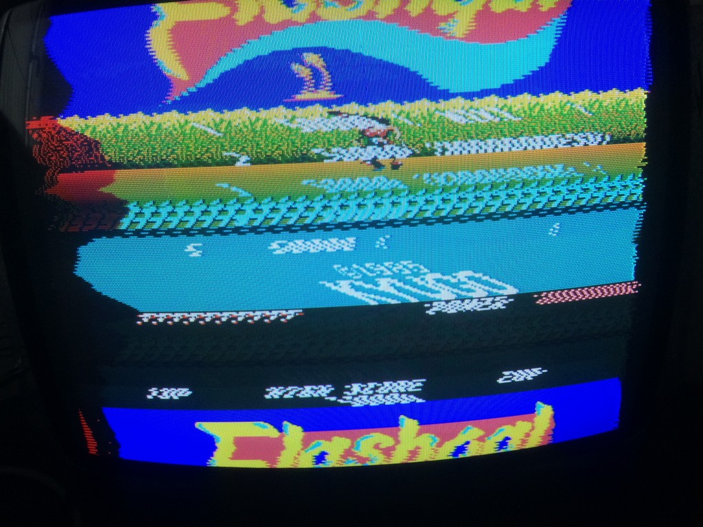
Anyway it seems that in these days I am very unlucky because the game once fired up had a sync problem
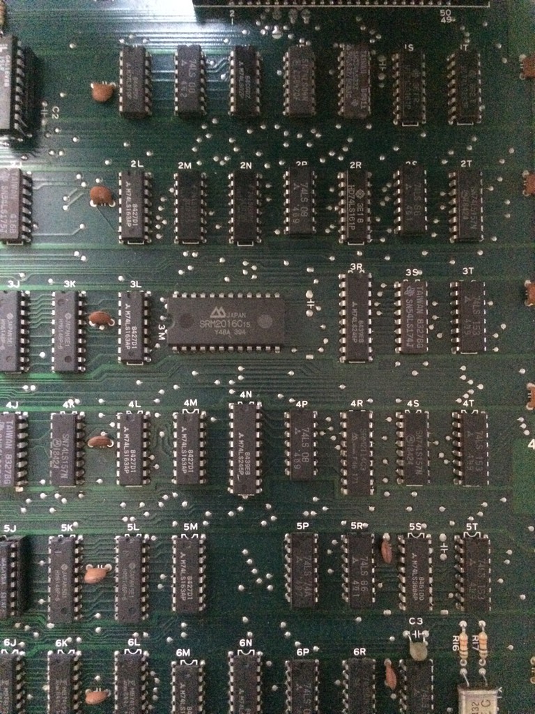
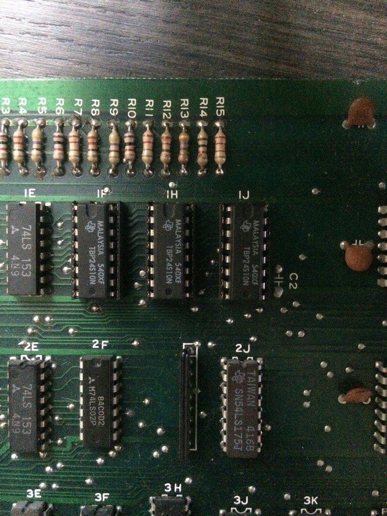
Tracing back from the SYNC pin I came to a 74LS08@2P
With the frequency counter I got very unstable readings so I proceeded to piggyback it with a good 74LS08 which restored the sync.
After changing it, it tested good out of circuit, yet with the new TTL in place I got a stable sync….
The screen looked very reddish so there was obiviously a palette problem
I checked the palette rams and they were all good so I dumped the colour proms until I found the RED component one @1J which didn’t match anything in MAME.
The prom is an 82s129 and it is almost impossible to find an empty replacement these days.
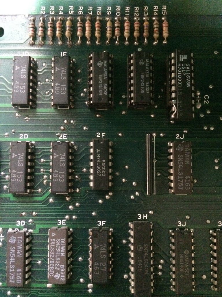
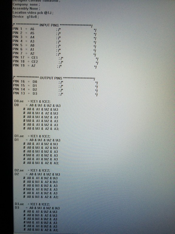
Therefore I went again for the Bprom to Gal replacement already used last year in another repair log:
Since the prom was the very same type I replaced for Mad Gear, I converted the prom file to the PLD equations using Elgen tool U2pa and I reused the same pin configurations which fits nicely without any major hardware mod except a jumper wire to connect GND to the correct pin on the GAL
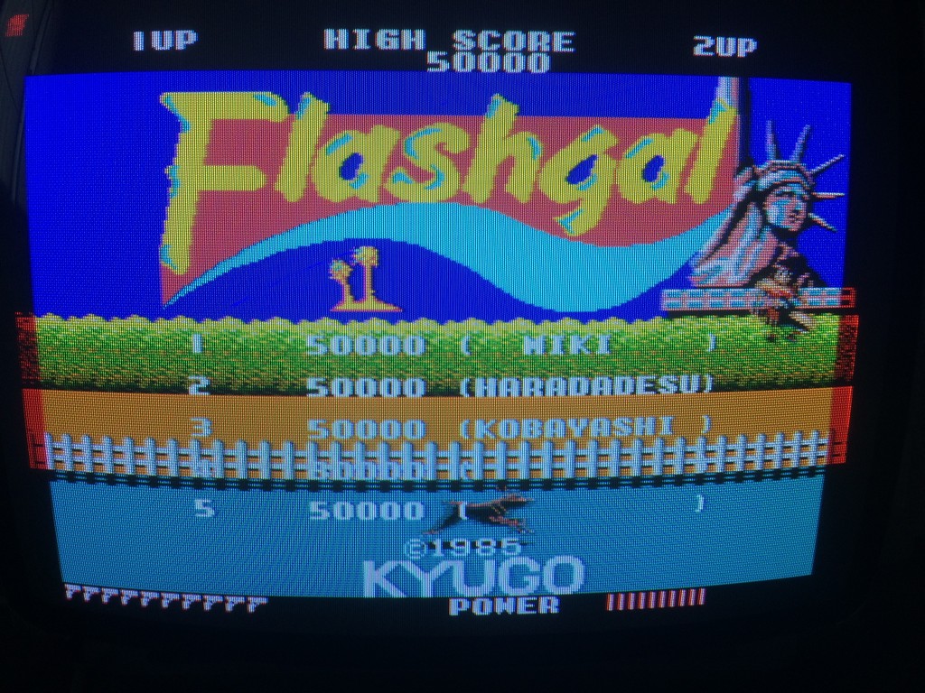
I tested the the game but I noticed something strange:
The colours were right but there were glitches on the left and right borders and also a flickering red component across all the screen (which cannot be seen on the static image offcourse)
At first I thought it was an access time problem with my GAL , therefore I burned the fastest one I had but no luck.
I tested directly the signals of the PROMS and found out that the CE pins were not tight to GND but were controlled by another ttl.
Soon it became clear why it didn’t work: the GAL was sending datas out of sync therefore producing artifacts.
Since I am not a programmer I asked to Elgen and Caius (who asked to Porchy) an advice how to replicate on the PLD a tristate behaviour.
All of them were very kind and in few minutes they informed me how tristate works on PLD equations
I added the needed modifications to my PLD equations by declaring each data pin enabled when pins CE1 and CE2 were low.
This completely fixed the colours on the pcb with no artifacts:
Again a big thanks to Elgen from https://elgensrepairs.blogspot.it/ for the invaluable tool and to Caius and Porchy for being always very helful