21/02/2020 10:59 ( AEST )
I’ve been meaning to update this page for awhile but work and life has got the better of me.
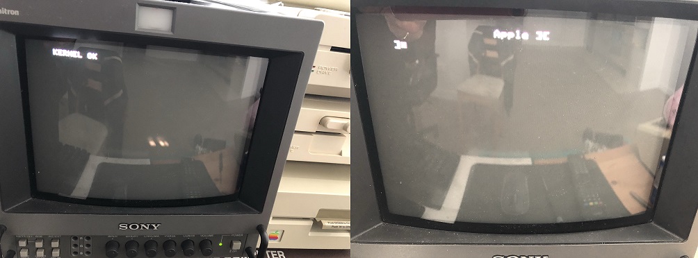
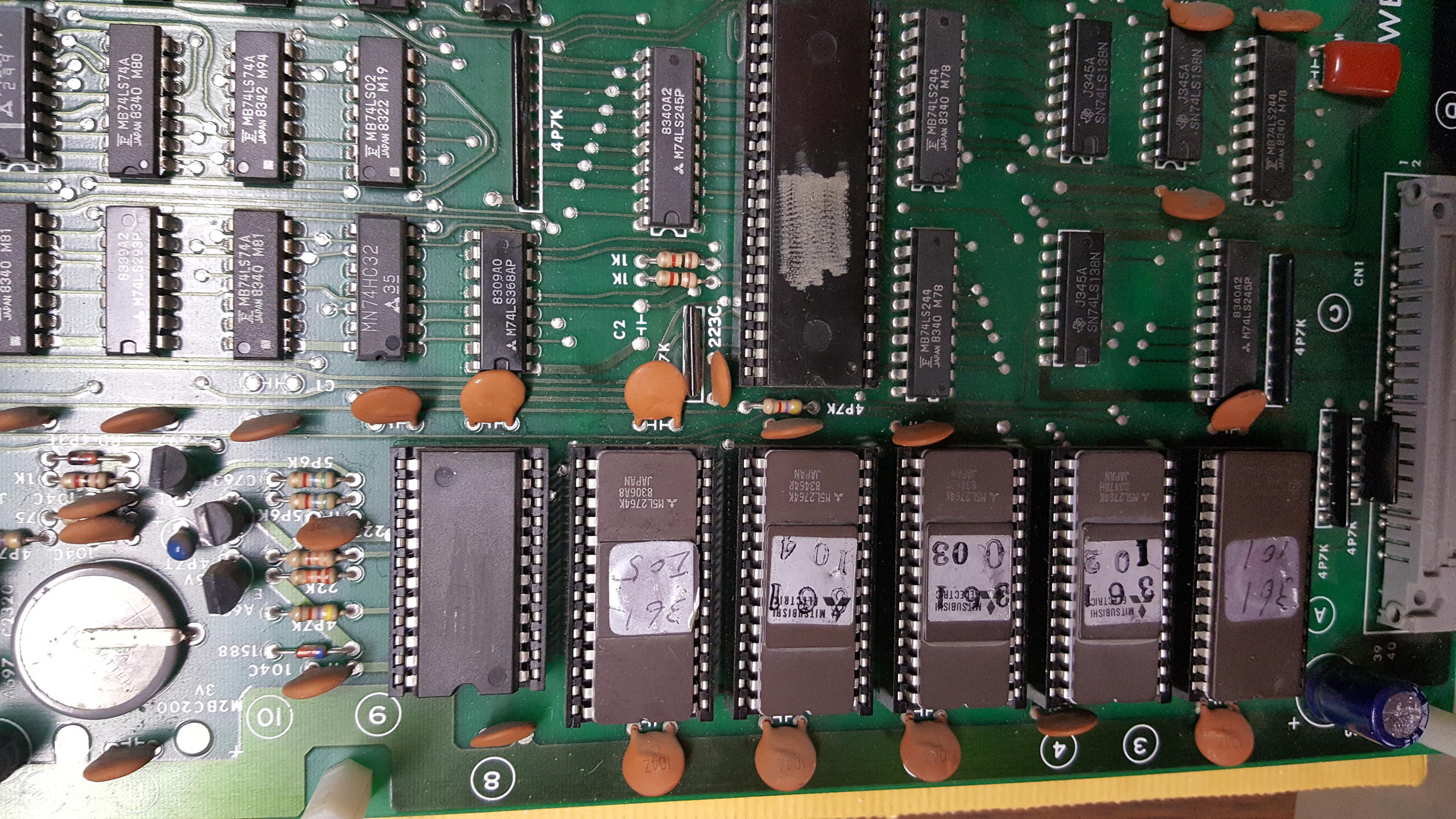
If your Track&Field/Hyper Olympic has the following layout then you have unencrypted roms and you will need this updated version of my diagnostic to run on this particular board. Note that this version will not run on boards equipped with a K1 cpu ( 42 pin custom IC ) or a game ( usually a bootleg ) with daughterboard that has a 6809 processor onboard, the daughterboard version also has some extra logic associated with it to decrypt/unscramble the opcodes.
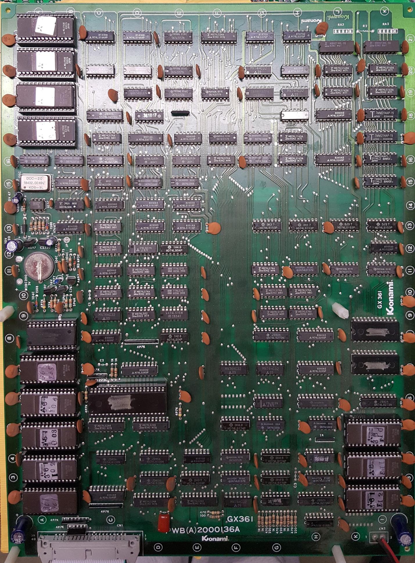
Note: The board does not have a K1 CPU but uses a standard 6809 processor to run the game. Decryption related circuitry is also absent from this version.
I have prepared a version that will run on this board.
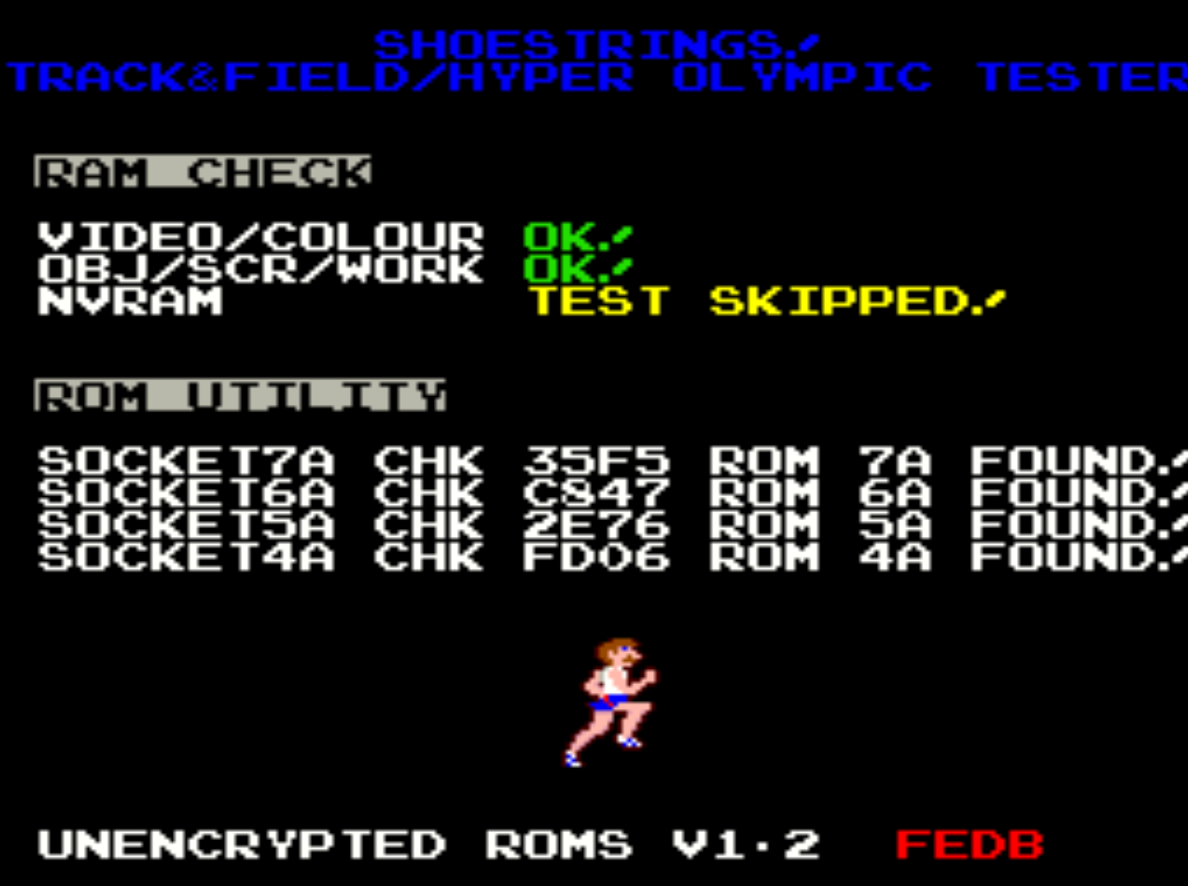
See TEST VERSION 1.2 – Unencrypted for download
9/02/2017
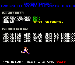
TEST 1.2 is now the current version which installs in socket 5A on Konami and Centuri versions.
- Fixed detection of ROM A7 [ $9E99 ] ( Hyper olympic bootleg) which broke in TEST 1.1
See TEST VERSION 1.2 for download
21/08/2015
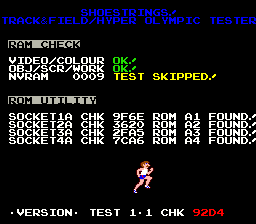
TEST 1.1
This is a test release. A BETA version will replace it and this post will be updated pending sufficient feedback. It has been reported by one tester that this version works on real hardware but more feedback is desired.
IMPORTANT: The diagnostic EPROM now installs @ 5A on the Centuri and Konami boards. For the Hyper Olympic bootleg install the EPROM @ A7 and for the NZ bootleg install @ 2A.
This frees up 4 sockets for verifying game EPROMs instead of only 3. Since 5A is mapped to 0xe000-0xffff and the reset vector is obtained at 0xfffe/0xffff, it made sense to move the test rom to this socket.
See TEST VERSION 1.1 for download
IMPORTANT: All versions below install in socket 1A
18/08/2015
Bullet points represent items fixed in the current version.
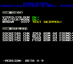
BETA 1.3 is current.
- ROM A1 FOUND! text missing when generated check-sum verifies successfully in socket 3a & 4a.
TODO: Future versions will install in socket 5a. The main reason for this change is to ensure the test rom boots since the 6809 obtains the reset vector from EPROM A5 ( 0xfffe ), there is a chance that the reset vector could be corrupted if the game EPROM A5 is bad. Moving the code to run from socket 5a will prevent such an event and also make the first 4 sockets available for verifying an A5 EPROM or any others.
See 1.3 for download CHK: F3E9 CRC16: 1421
16/08/2015
BETA 1.2
- Further checks suspended if video ram/colour ram is bad. Priority given to preserve NVRAM/high scores. ( worst case scenario – screen totally unreadable ).
- Introduced audio alert. 5 beeps for bad video ram 12H, 6 beeps for bad colour ram 11H.
- Provided work around to keep tiles on screen if scroll ram is detected as bad.
See 1.2 for download CHK: F3EB CRC16: 5695
Special thanks goes out to Purity on UKVAC for his help with testing and feedback.
1/08/2015
BETA 1.1
- Fixed SFX menu. Speech now plays from sound index 0x80
If you believe there are missing sounds please report them in the comments.
See 1.1 for download CHK: 9909 CRC16: AB36
30/7/2015
BETA 1.0
- Bootleg rom support added ( see hyprolymb from the MAME set )
- Fixed watchdog reset issue during EPROM check routine
- Fixed character bank bug ( was displaying extra bank of null tiles )
- Added CRC of current software to version string ( calculated at runtime )
BOOTLEG – HYPER OLYMPIC ( hyprolymb )
ROM A1 $9E99
ROM A2 $35E8
ROM A4 $2FDC
ROM A5 $7DD2
ROM A7 $F932
TODO: Fix SFX test in diag mode. Speech is not playing.
See 1.0: CHK: 9F7E CRC16: 2F6F
26/07/2015
BETA 0.9
- Support for Hyper Olympic roms added
- MISC code improvements
See 0.9 CRC16: 70E6
See below for correct 16 bit checksums matching your set.
Pre-calculated ROM Checksums.
KONAMI – TRACK & FIELD
ROM A1 $9F6E
ROM A2 $3620
ROM A3 $2FA5
ROM A4 $7CA6
ROM A5 $FEEB
CENTURI – TRACK & FIELD
ROM A1 $9DBE
ROM A2 $3CA7
ROM A3 $17C8
ROM A4 $569E
ROM A5 $E991
KONAMI – HYPER OLYMPIC
ROM A1 $9E79
ROM A2 $35E8
ROM A3 $2ECE
ROM A4 $7DD2
ROM A5 $F932
25/07/2015
BETA 0.8
- Support for Centuri roms added.
See 0.8 CRC16: 9EBE
24/7/2015
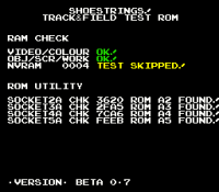
BETA 0.7
This EPROM installs on the CPU board @ 1A. This does not replace the original software in 1A but is only used as a means of testing the main-board, sound and video.
Diagnostic mode is accessible by holding down player 2 start whilst powering the game on.
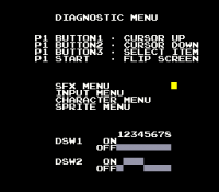
In the normal mode ( power up tests ), nvram tests may be skipped to preserve high score data if so desired. This is done via DIP 8 of SW2. A ~10 second countdown is also included even if you desire to test your nvram, in this mode nvram tests may also be skipped by pressing the “player 1 button 1”.
Power up tests also include a rom utility. This currently identifies track & field software in any of the 3 available sockets ( 2A to 4A ). For example, an A1 ROM installed in any of the above available sockets will still be identified for its designated 1A socket.
Important: A5 ROM needs to remain in socket 5A, this is because the 6809 obtains its reset vectors from this ROM. If the test rom or game fails to start and the screen is full of zeros, verify the A5 rom manually.
Note: That this is a very BETA release and is currently in the testing phase, bugs are expected. Use at your own risk if you love those high scores.
See 0.7 CRC16: 8C8A