Today I’ve uploaded the latest version of my BINman software.
This version is v4.3.2 and has had some rewrites and a few extra features added.
First is the ability to deinterleave the bytes of a file into nibbles.
Second feature added can be found under the “Special” menu. It was added as a request from a user. This swaps the nibble values from one byte and the adjacent byte then deinterleaves that file. For example an original file of: “12 34 AB CD” will output two files, one containing “13 AC”, the other “24 BD”.
Its not something I’ve ever had the need for but obviously someone wanted it so here it is.
As usual it can be found in the “Downloads/PC Software” section.
GeneralComments Off on Jaleco ‘JK-03’ reproduction successfully tested
Dec312018
Some time ago I made a reproduction of the Jaleco ‘JK-03’ custom SIL used for inputs handling on some Mega System 1 PCBs but at that time I was not able to test it due to the lack of a proper PCB hence I asked for some volunteers.You can read the post here:
Today I can report the reproduction is fully working thanks to the test carried out from the user ‘Astro X’ of AP forums on his Saint Dragon PCB with missing ‘JK-03’ (actually an hack was installed as workaround) :
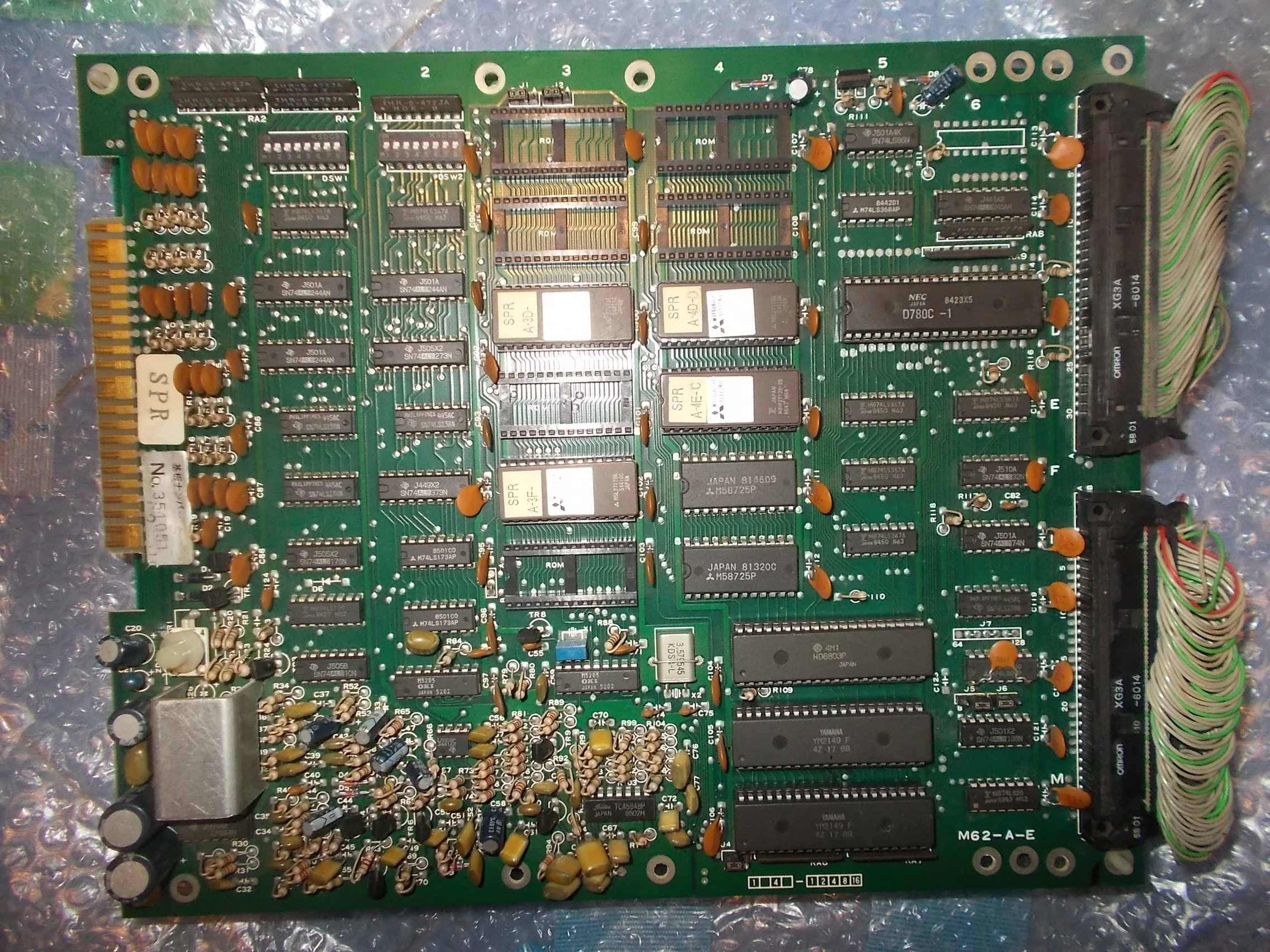
I received for repair a quite rare original Spelunker PCB (on Irem M62 hardware).Board is a three stack one made of a top board (which carries most of sound hardware) :
SOUND board
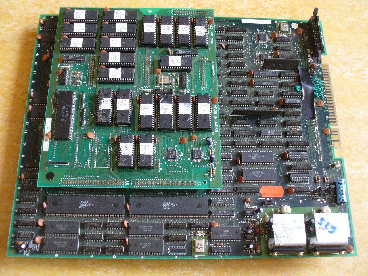
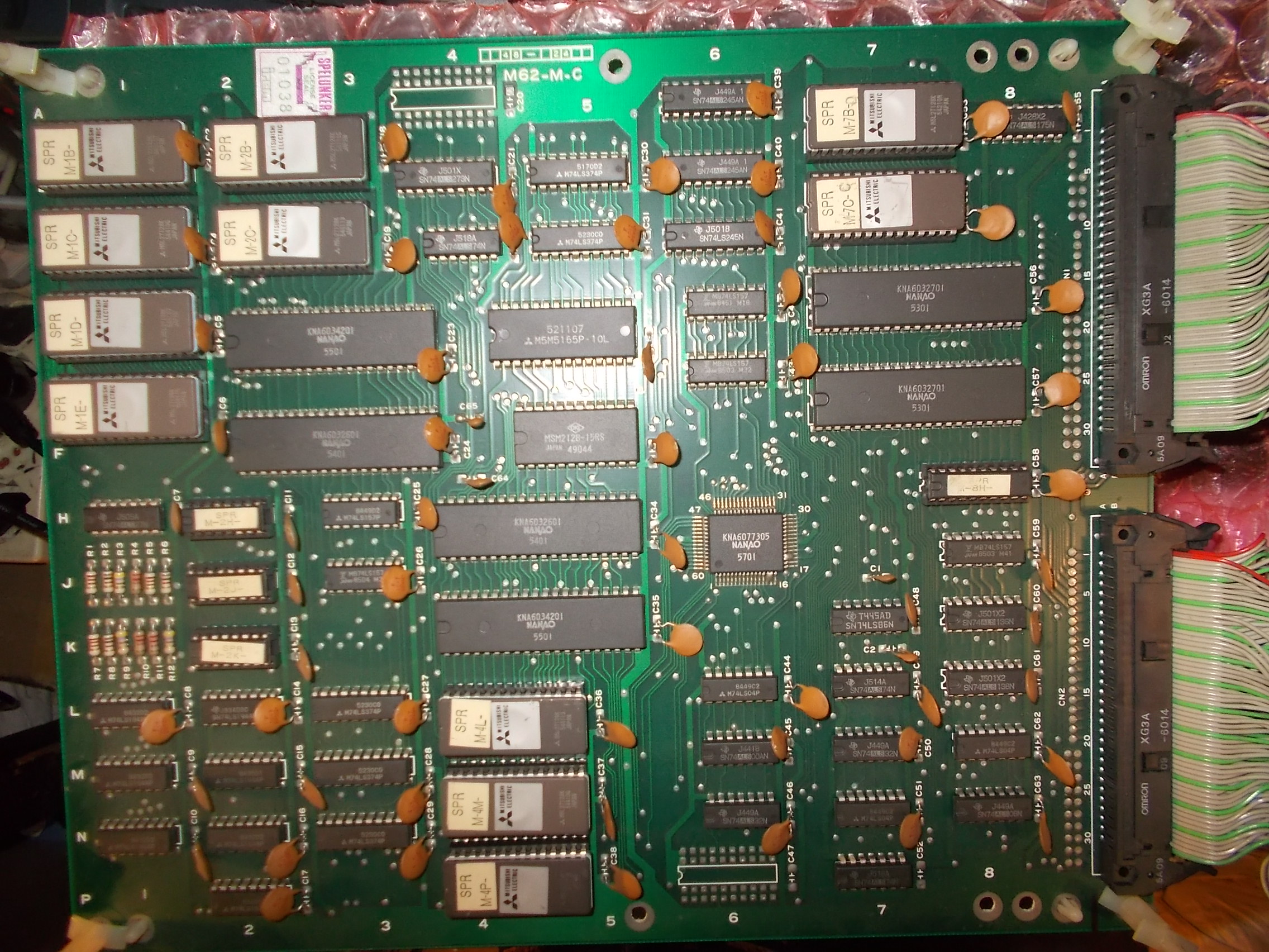
A middle CPU board (specific for each M62 game) :
CPU board
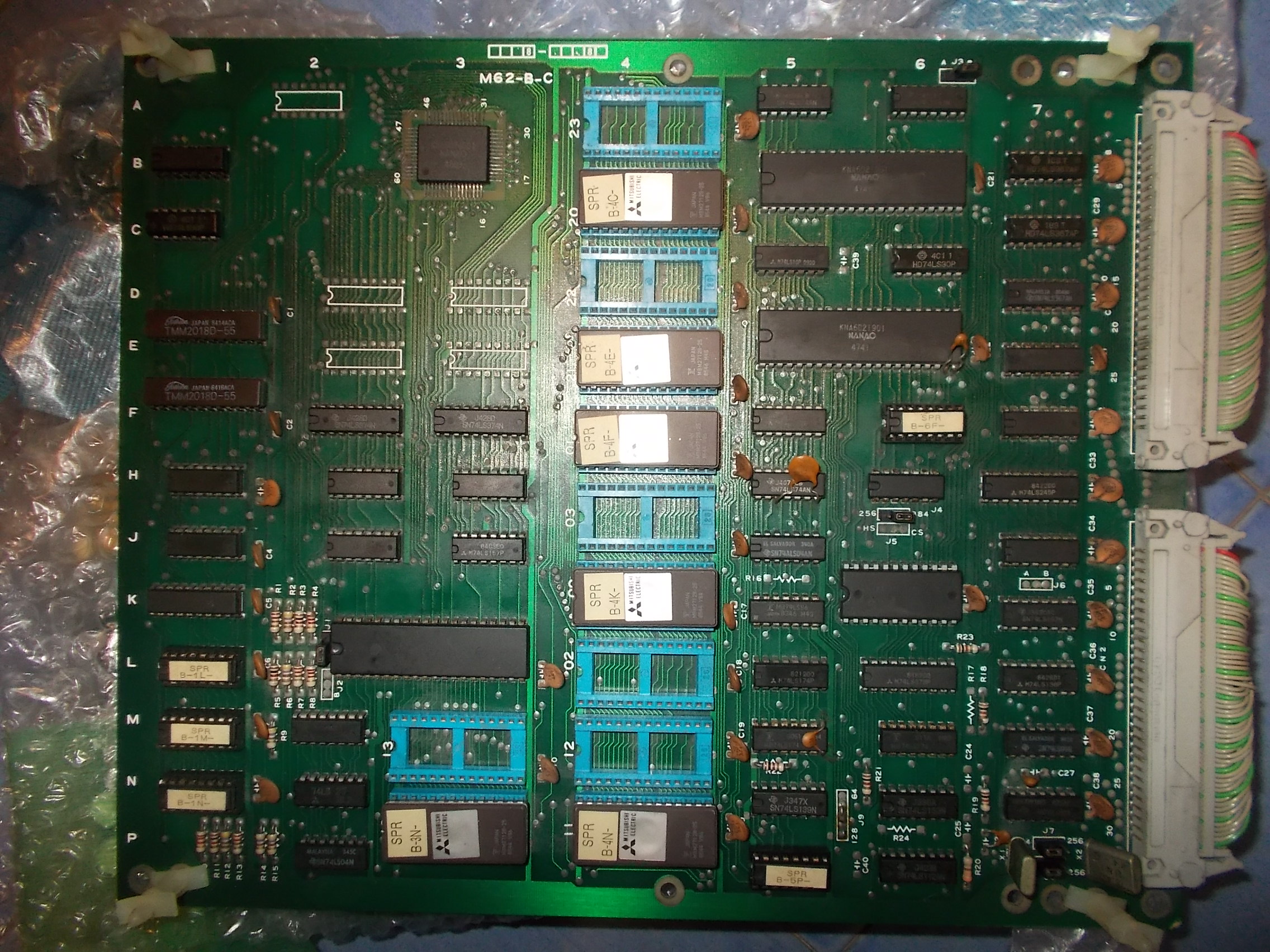
And a bottom VIDEO board :
VIDEO board
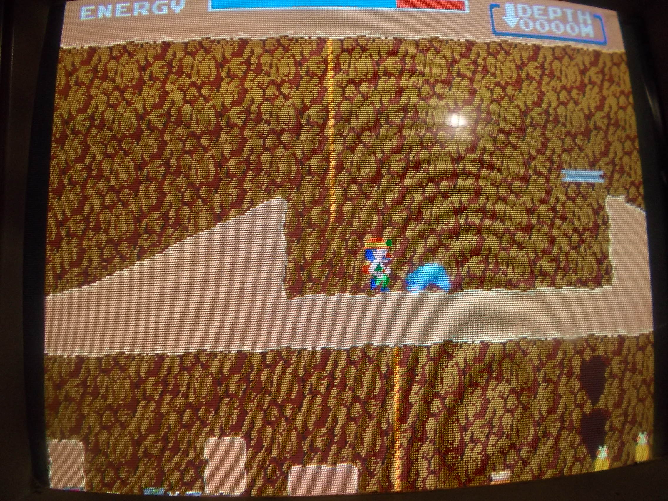
The PCB had severe GFX faults, the sprites were only lines vertically stretched all over the screen:
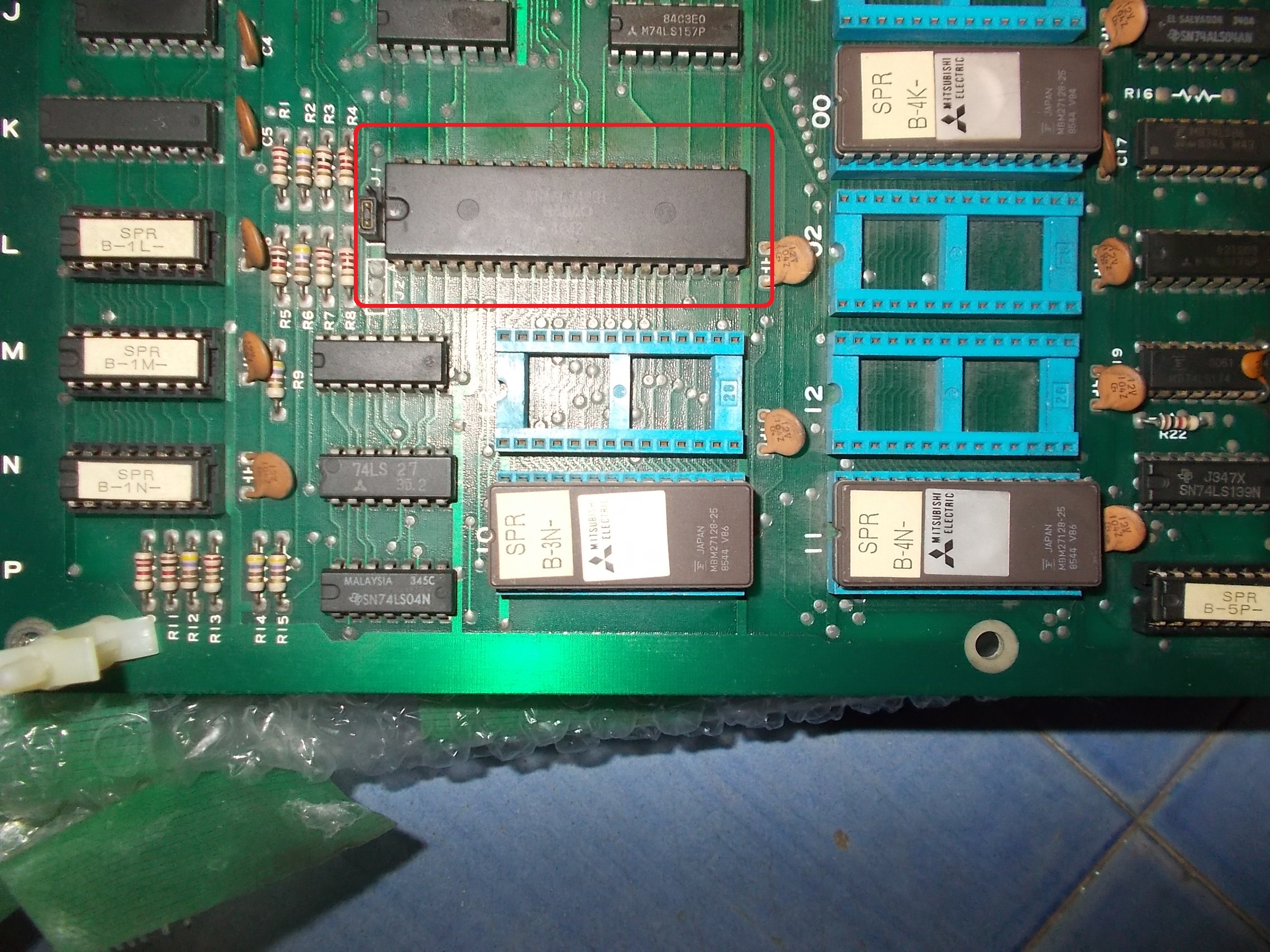
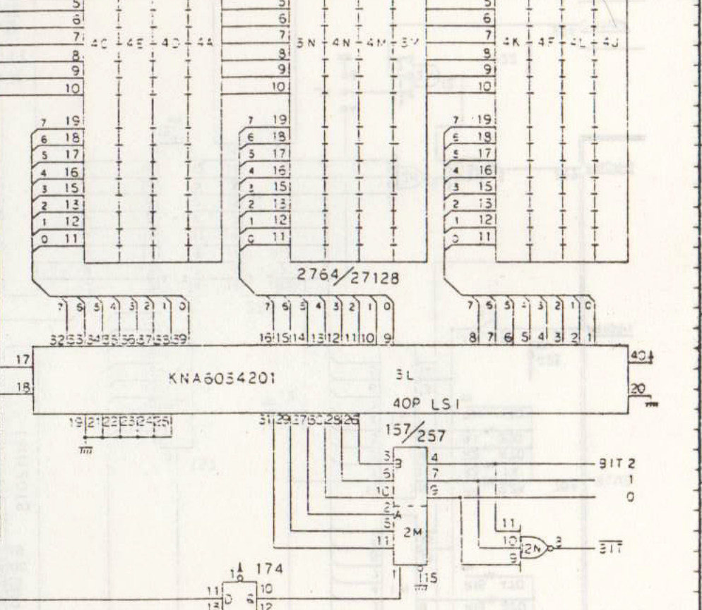
All the sprites circuit lies on bottom VIDEO board which is the same for all games that run on M62 hardware.Looking at Kung-Fu Master schematics I could figure out that data bits from sprite ROMs are fed into the custom marked ‘KNA6034201’ :
Custom ‘KNA6034201’ in DIP40 packageCustom ‘KNA6034201’ schematics
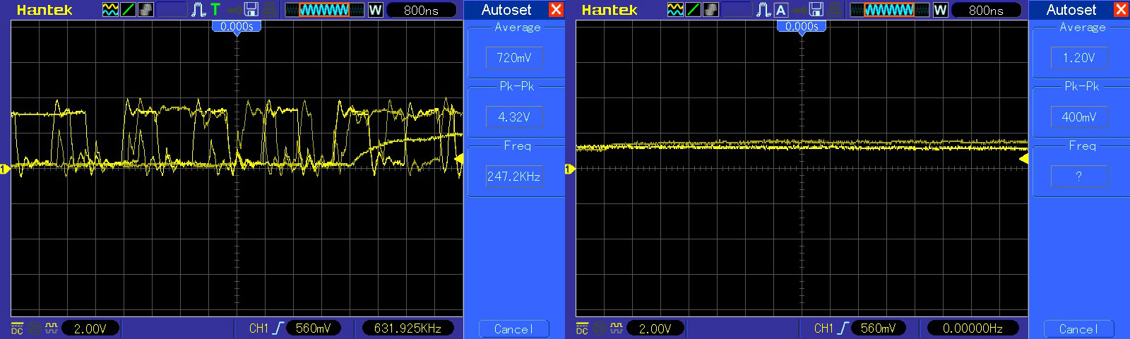
The inputs were all active but most of outputs floating:
So the custom was most likely internally faulty.Luckily I have done a reproduction of this component some time ago.You can think of it like a 24-bit parallel to serial shift register:
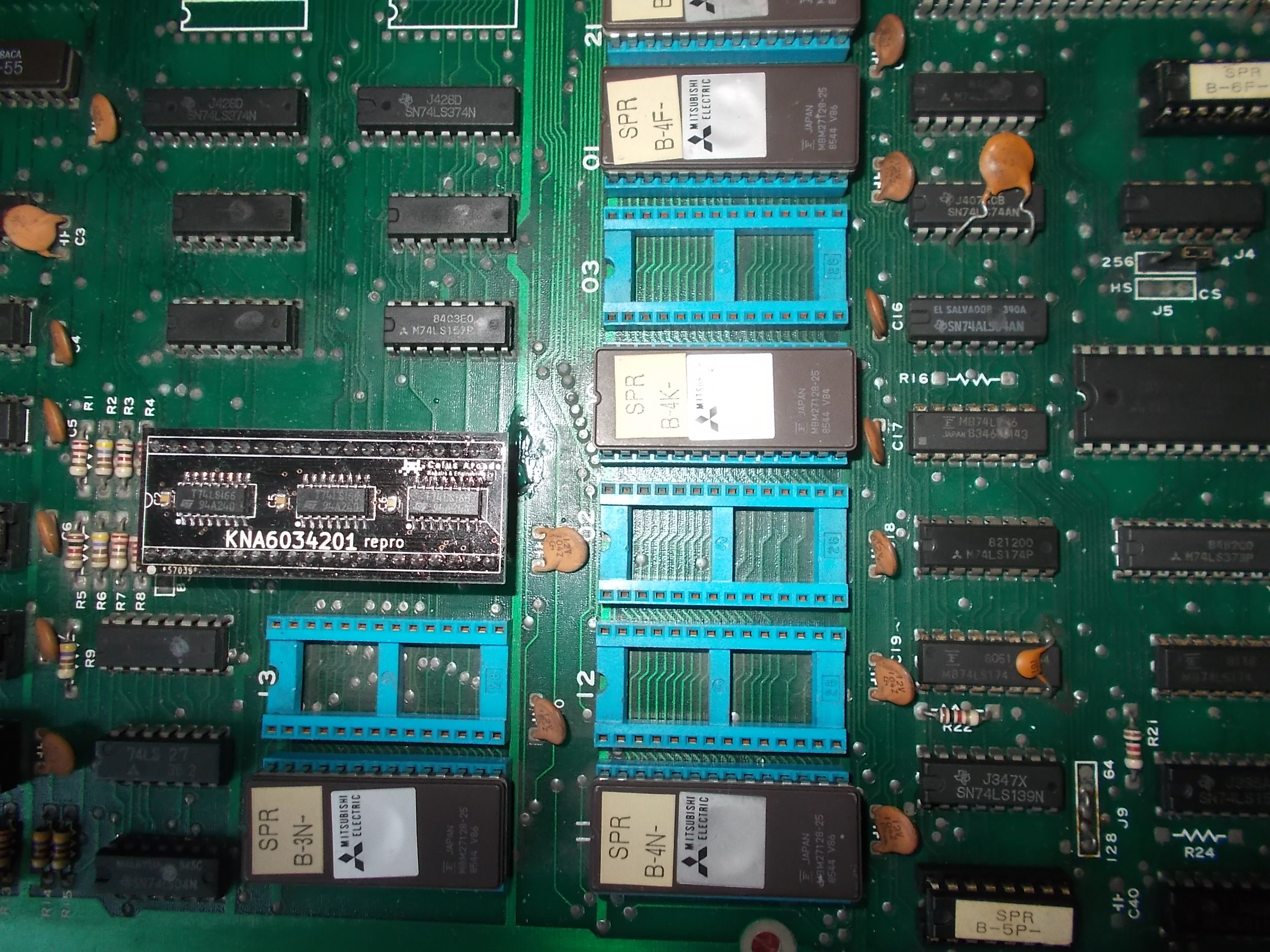
I removed the custom and installed the reproduction:
‘KNA6034201’ repro
The sprites were back but not perfectly as they were lacking of lines and misplaced too:
Sprites not yet perfect…
The sprite line buffer consists in two 2k x 8-bit static RAMs (Toshiba TMM2018 used here) :
Sprite line buffer
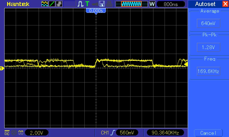
Probing them revealed on both a floating address line (pin 1, A7) :
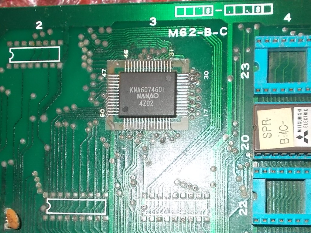
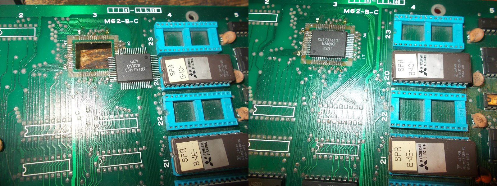
Address lines are generated by the surface mounted custom ‘KNA6074601’ :
Custom ‘KNA6074601’
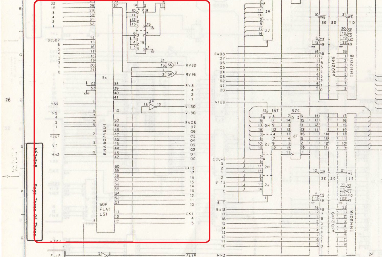
Its pinout/implementation from Kung-Fu Master schematics :
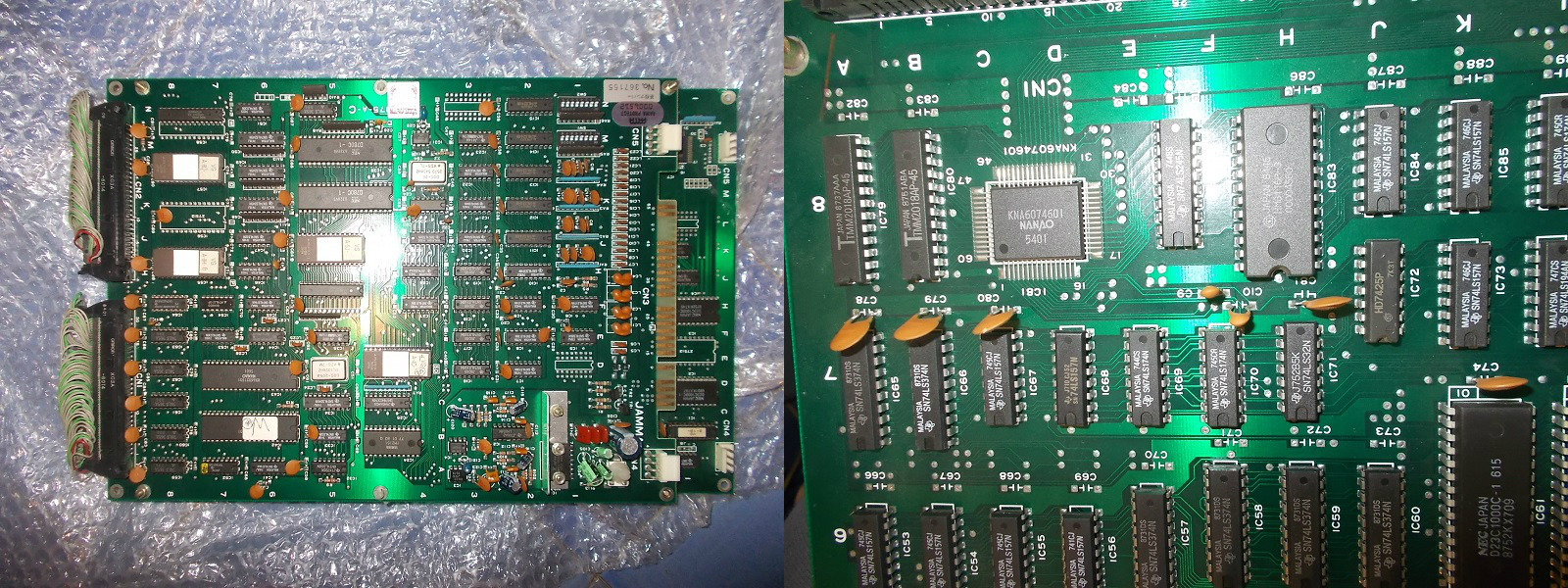
I had no other choice than replacing this part so I asked the owner to look for a donor board.He found and sent me a Vigilante PCB which carried the ‘KNA6074601’ on bottom board :
Vigilante donor board
I removed the faulty one and soldered the spare back :
I have two Toki pcbs in storage, both with sprite errors. I saw a video from lukemorse1 (who actually inspired me to start repairing arcade pcbs) on youtube where he worked on a Toki pcb, also with sprite errors.
Here’s how the error on board #1 looked like:
So there are blocks surrounding the sprites.
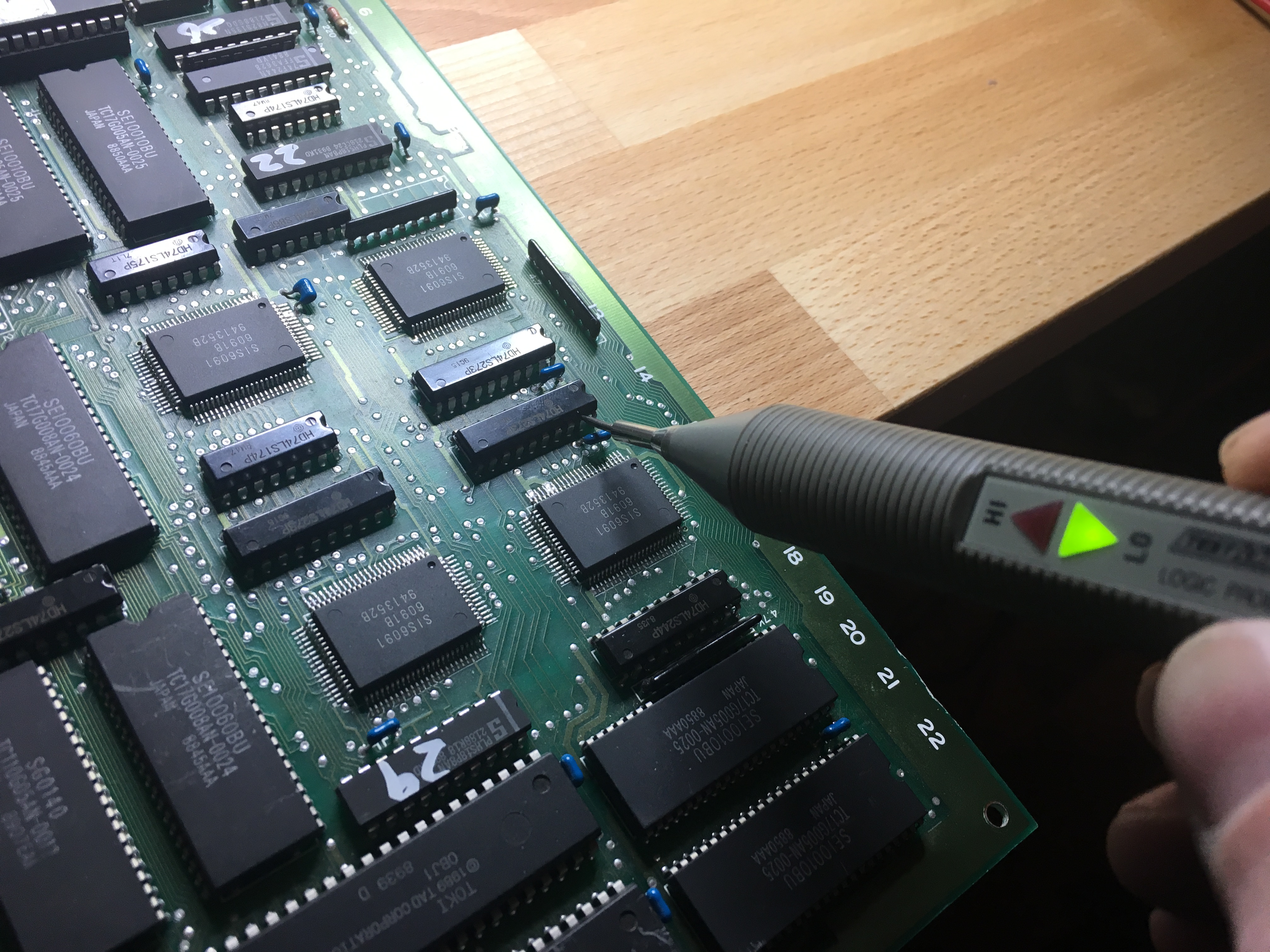
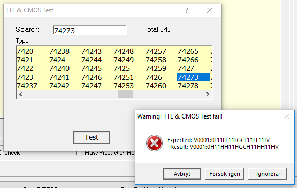
From Luke’s video (https://youtu.be/Czdt_yTNRTs) I identified the area responsible for sprite handling and I quickly found a 74LS273 with a stuck output at pin 19:
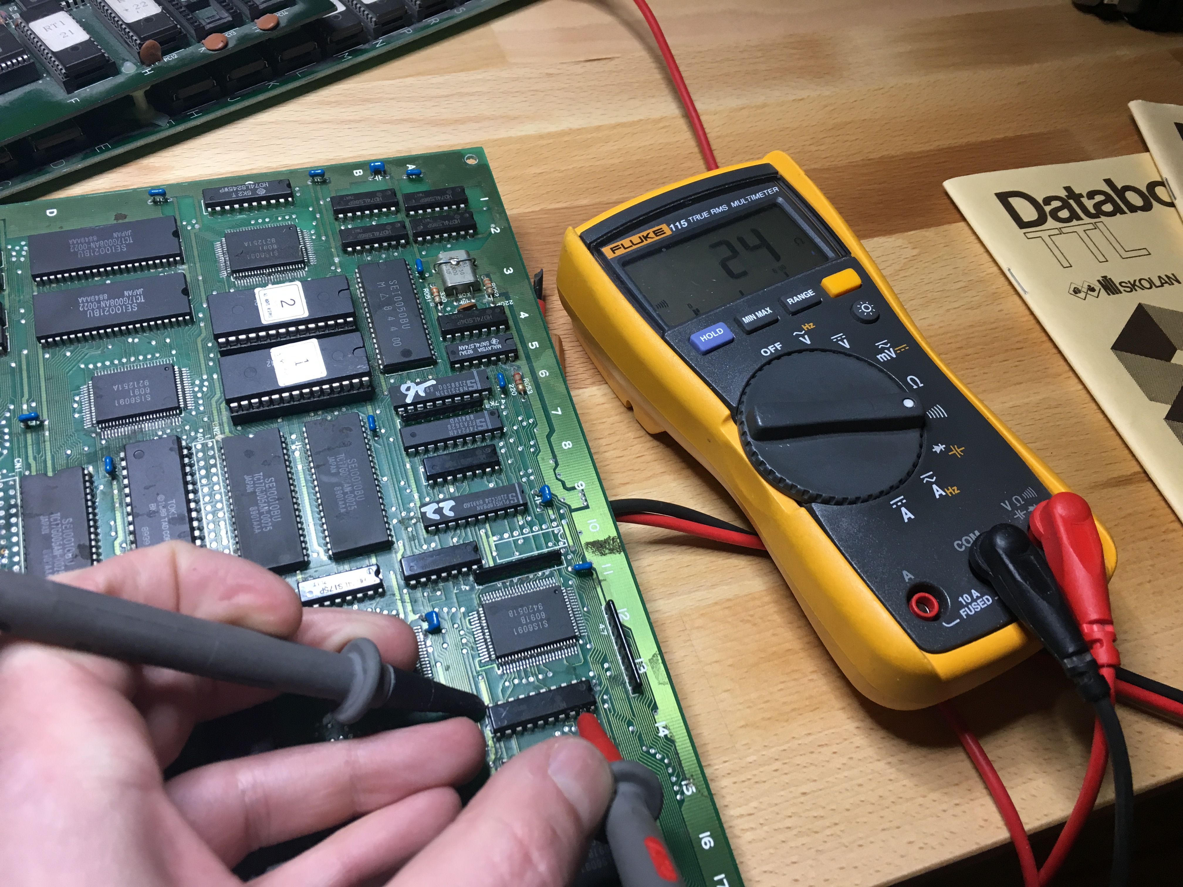
Checking with the multimeter, I found that this pin was almost shorted to ground:
I quickly desoldered the IC and tested it with my VP-398
Replacing it with a working 74LS273 made the sprites appear as they should:
So a big thanks to lukemorse1 and also as always to caius for always helping out 🙂
While searching through some documents from Data I/O I came across a bunch of logic diagrams for various PLD’s. One of them was for the CK2605.
As I’ve not seen this in the wild before I thought I’d upload it.