Sockets arrived yesterday and chips arrived a day later, great timing because I’d already had the socket installed by the time the chips arrived.
I’ve decided to remove the backing on one of the sockets, I really didn’t like the idea of trying to get my soldering iron tip in between the backing and pins so I removed it. My plan was to attach some double sided tape or hot glue to the backing/shim then apply it to the MB later, I didn’t want the chip to sit so low in it’s socket in case it needs to come out later.
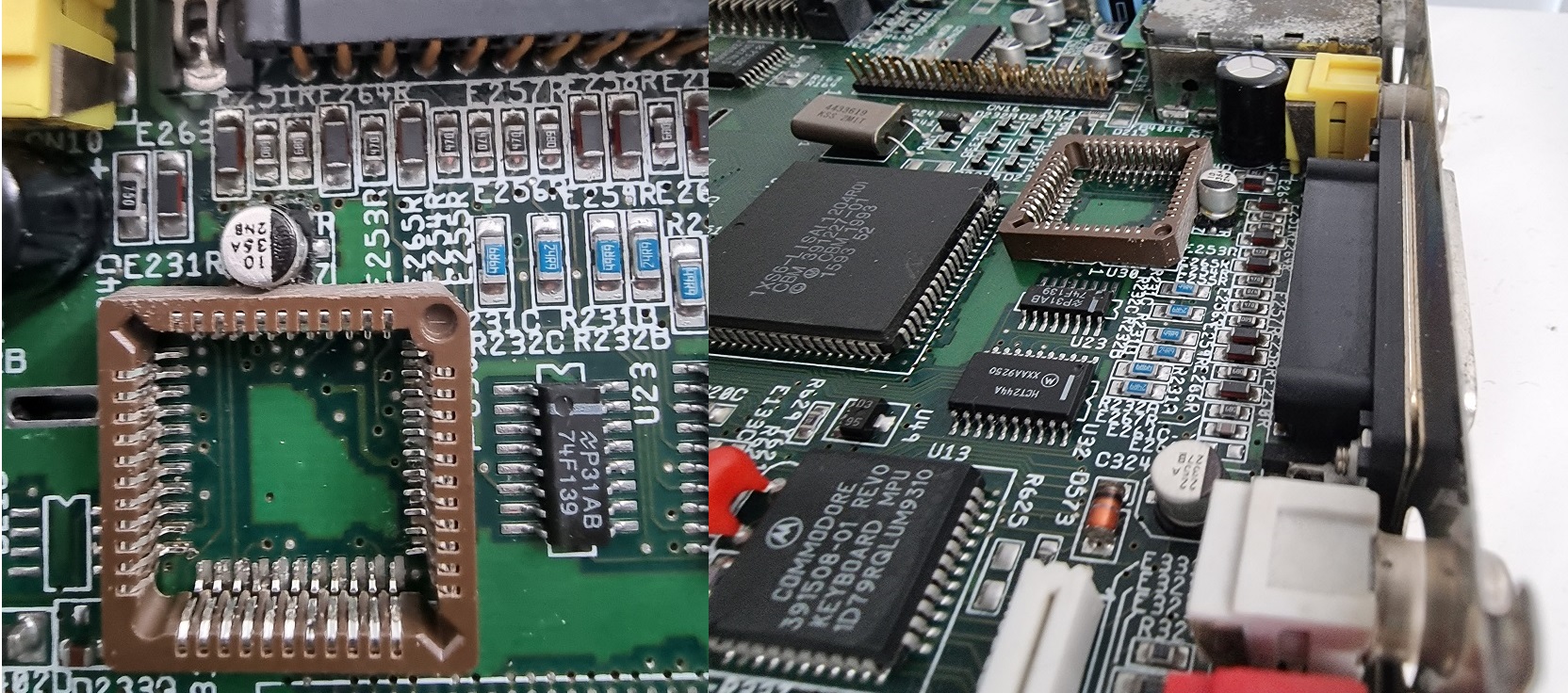
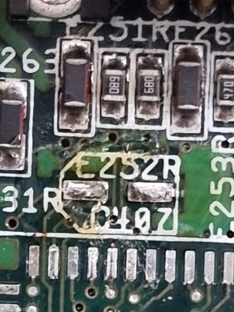
After lining up the pins, I had an obvious problem here. The base of the SMD capacitor at C407 in the video decoupling circuit wont allow the socket to sit flush so I decided to remove it, solder the socket in place then add the capacitor later.
Out with the old and in with the new. Socket soldered into place and connections inspected with a Microscope, then the 10uf capacitor replaced with a brand new one.
The following day later in the afternoon I received a package containing these. Who sends electro static sensitive devices in a plastic satchel ? More over the devices were clearly de-soldered/pulls yet advertised as new. Will avoid this seller in future.
I chose the cleanest of them all ( top right ). I then installed the plastic shim with some double sided tape to the bottom of the socket and installed the chip and tested with success.
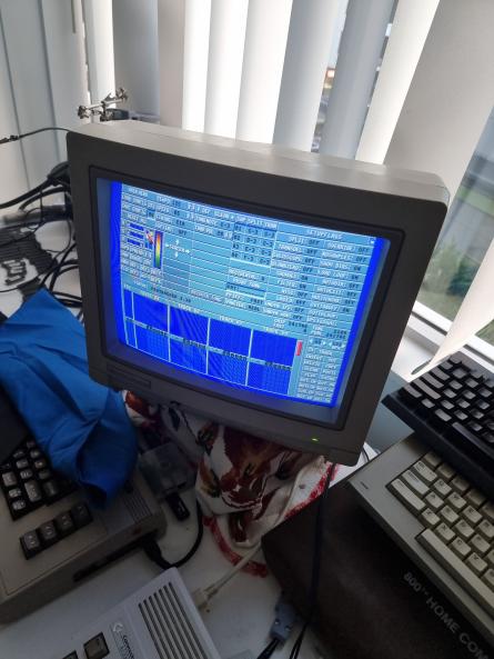
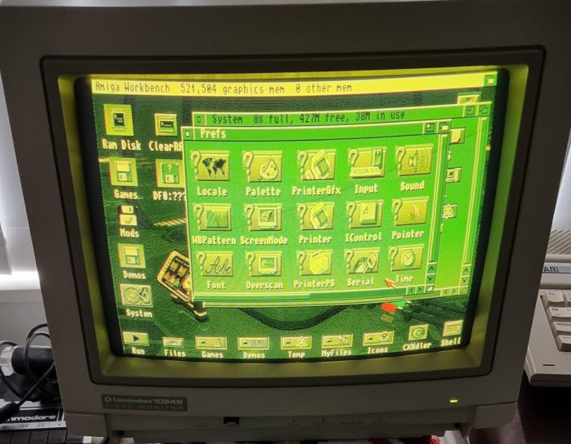
Whilst installing and carelessly adjusting my CF card in my A1200 with it switched on, I managed to short out some component on the motherboard via the shield which caused the machine to reboot and then come up with the following screen.
You can clearly see that blue is completely missing.
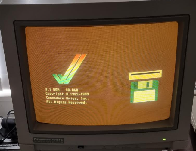
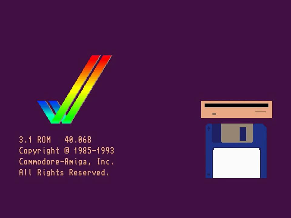
A healthy kickstart screen should look like this
I wasted no time getting to work after cursing myself for 30 minutes or so and feeling bad all night.
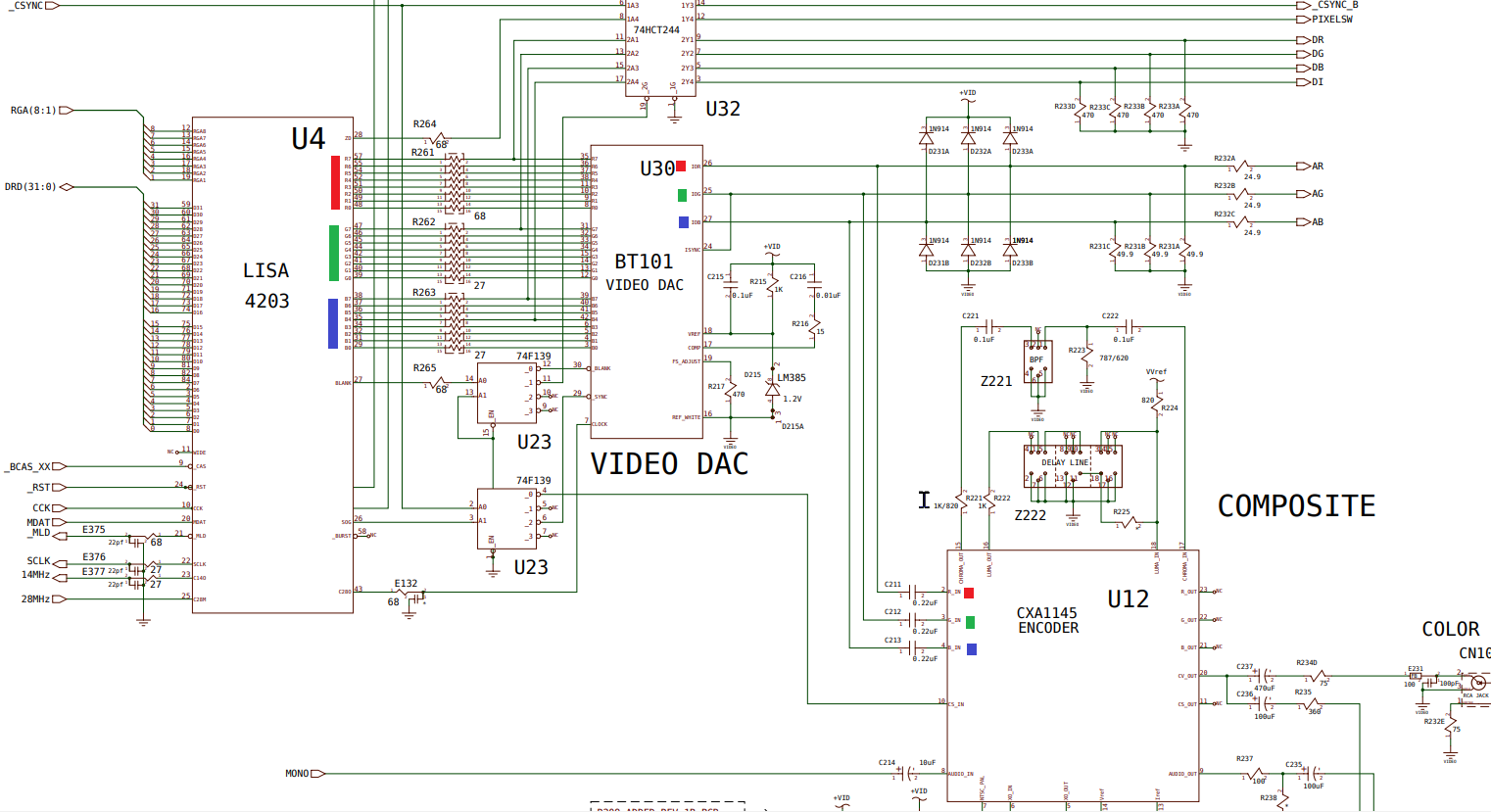
1st step was to figure out where the fault actually was, so I consulted the schematics to understand the design and get an idea of where to start.
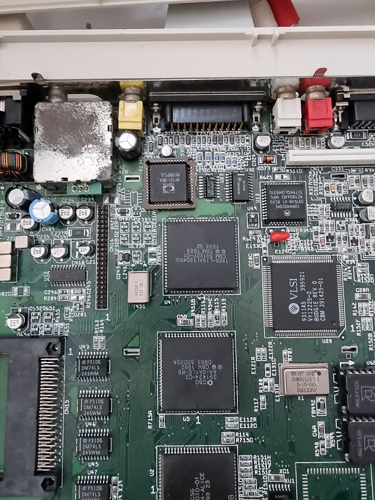
I have clearly marked the important parts of the drawing by marking each of the 3 RGB colours over the signals. First of all, we have an AGA ( Advanced Graphics Architecture ) custom chip called LISA which generates the colour information internally amongst other things, this must be converted to analog via the video DAC which accepts 24 bits of colour information from LISA and then passes those analog signals directly to the 23pin D-SUB connector on the back of the A1200.
The same 3 RGB signals generated by the video DAC are passed to the Sony Encoder chip for composite signal and also RF out to a TV.
The issue was also reproduced on the composite out, this would confirm the encoder just gets its RGB signals from the DAC and to look elsewhere. Unlike the Amiga 600 design which uses no DAC but uses the same encoder to pass RGB to the 23pin D-SUB, the A600 video output design is similar to the video hybrid method used in the A500 for generating RGB.
Thankfully we have a similar problem here from RetroGameModz that I used as a reference which describes the troubleshooting process. I really liked his use of Protracker to trouble shoot the colour, this proved very useful.
In Protracker, I turned Red and Green signals to the absolute minimum and adjusted the slider for Blue and see no change at all. So with my scope I verify the signals coming out of pins 25,26 and 26 of the video DAC. These are labelled IOR,IOG and IOB respectively. I could see valid waveforms on both on IOG and IOR but a flat line ( low ) on IOB no matter where I positioned the blue slider in Protracker via setup from the main menu. This explains the lack of blue.
So either, the 8 bits for blue were stuck on the output of LISA or I had a bad video DAC.
I then attached my logic probe to 5v somewhere inside the machine and adjusted the slider in Protracker whilst probing R,G and B signals. To my relief my logic probe responded to each and every single one of the 24 bits coming out of LISA. So LISA was spitting out colour information but the DAC was obviously not going to deal with blue. I repeated the same measurement on IOB output of the video DAC this time with the logic probe which shows its held low regardless of the position of the slider, further confirming the lack of waveform there with the scope.
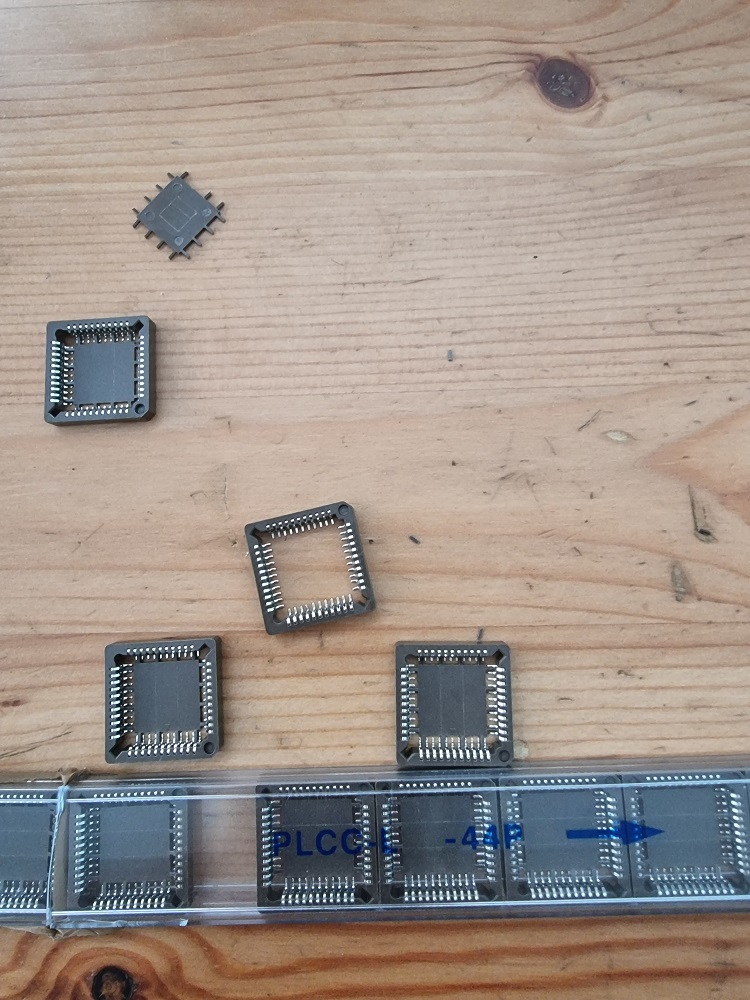
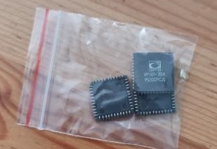
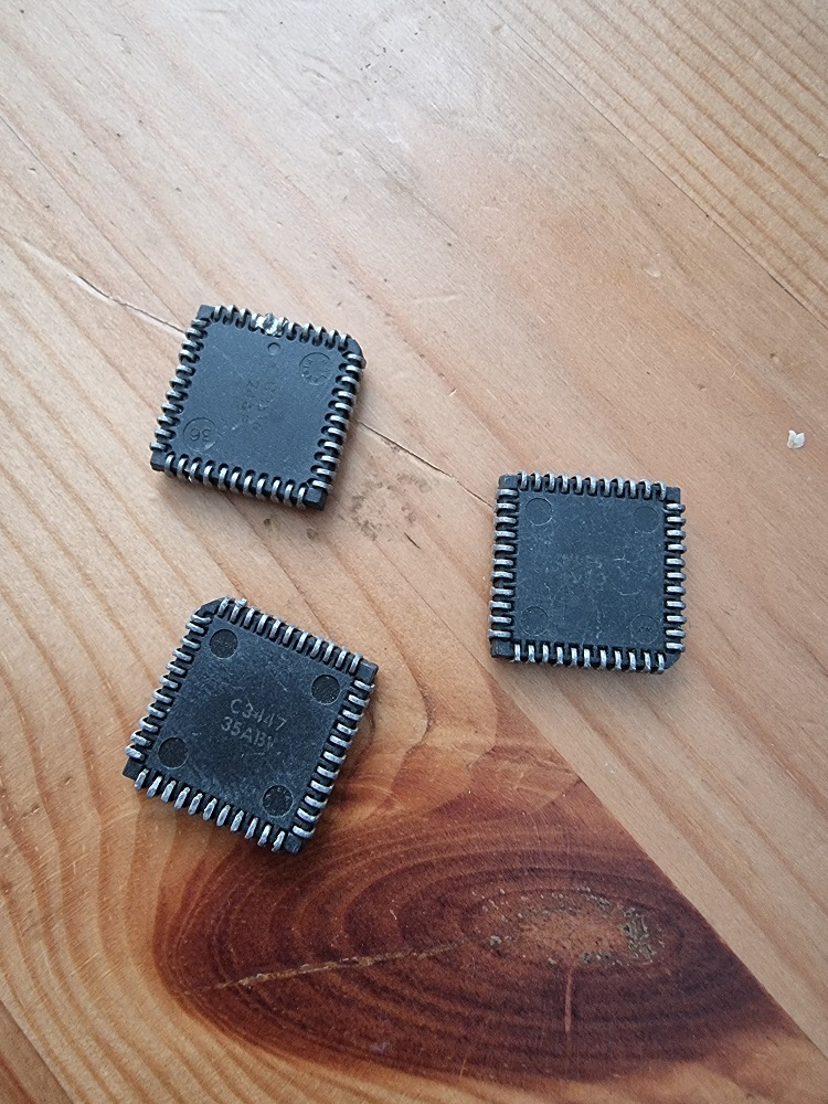
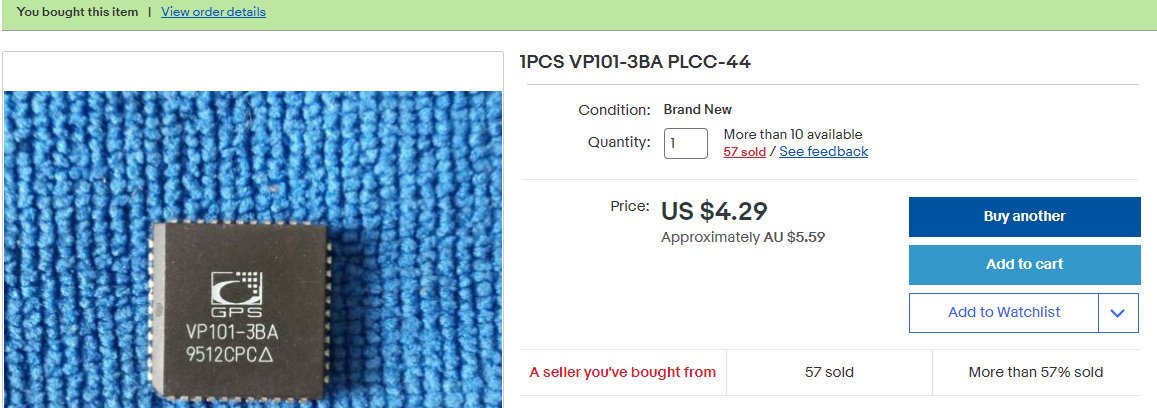
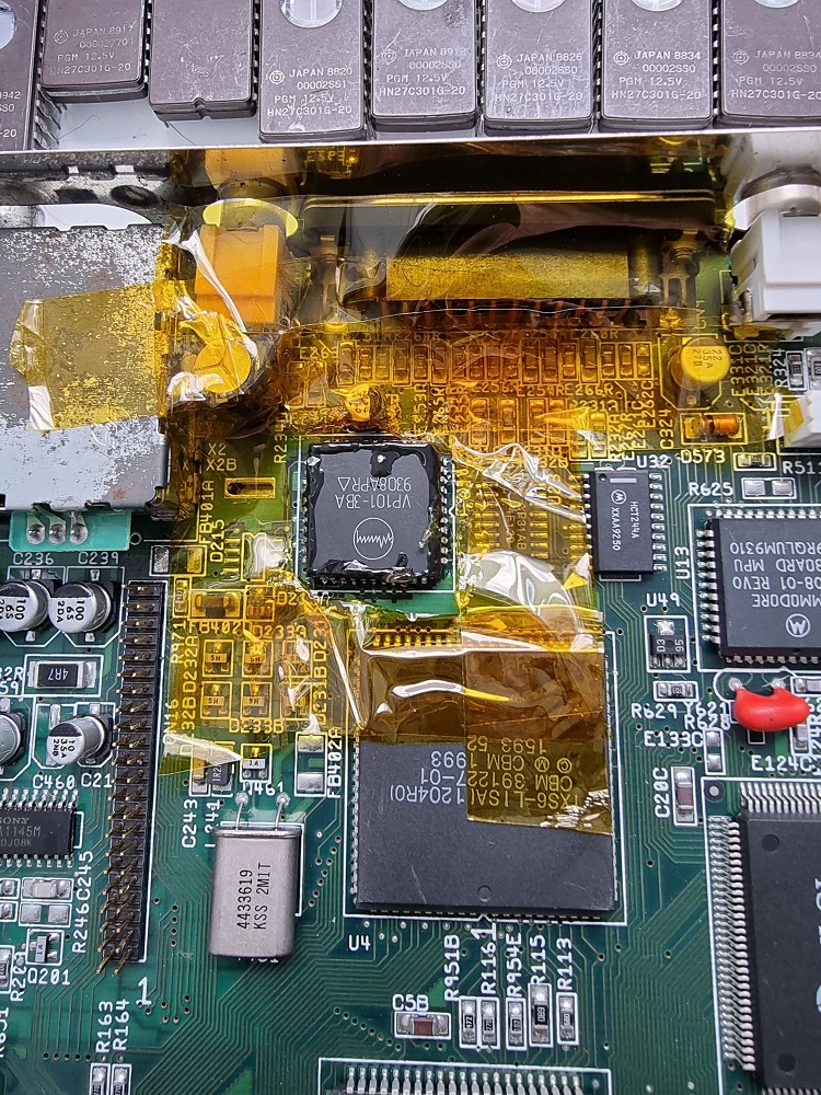
I wasted no time ordering some replacements. 3 x VP101-3BA manufactured by GPS/MITEL and some 44pin PLCC sockets.
So currently waiting for these to arrive from China, delivery time is 2 months.
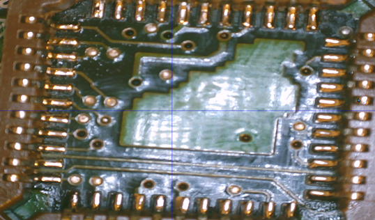
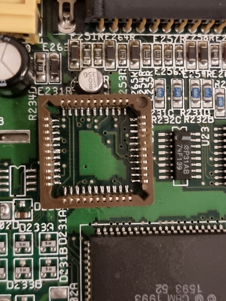
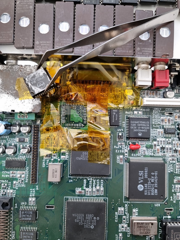
And in preparation I couldn’t wait to remove the faulty component from the A1200. First step was using a liberal amount of polyimide tape ( this stuff is expensive but will save you from grief ) to protect surrounding components from heat exposure, I applied some flux and then heat the chip to around 200 for 1 or 2 minutes, then raised it temp to 350 to finish off.
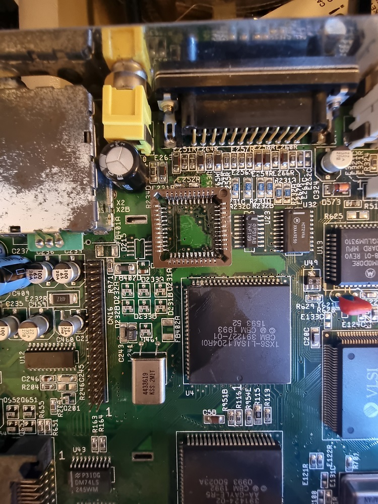
I had this cleaned up nicely. Now just waiting for the spare parts to arrive for a part 2.
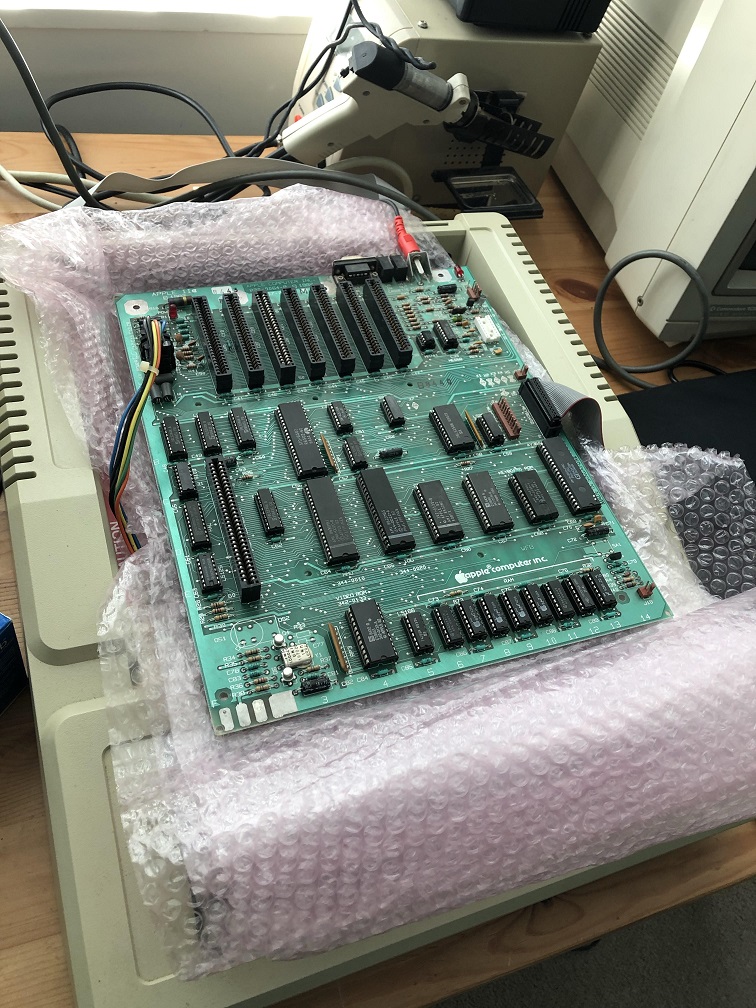
I recently received this Apple IIe PCB from the U.S to try my luck on salvaging the 60hz IOU and using it in my International NTSC board in the hopes of getting colour which I did successfully in my previous post. This board was advertised as untested, so that normally means “DEAD” and I assumed so.
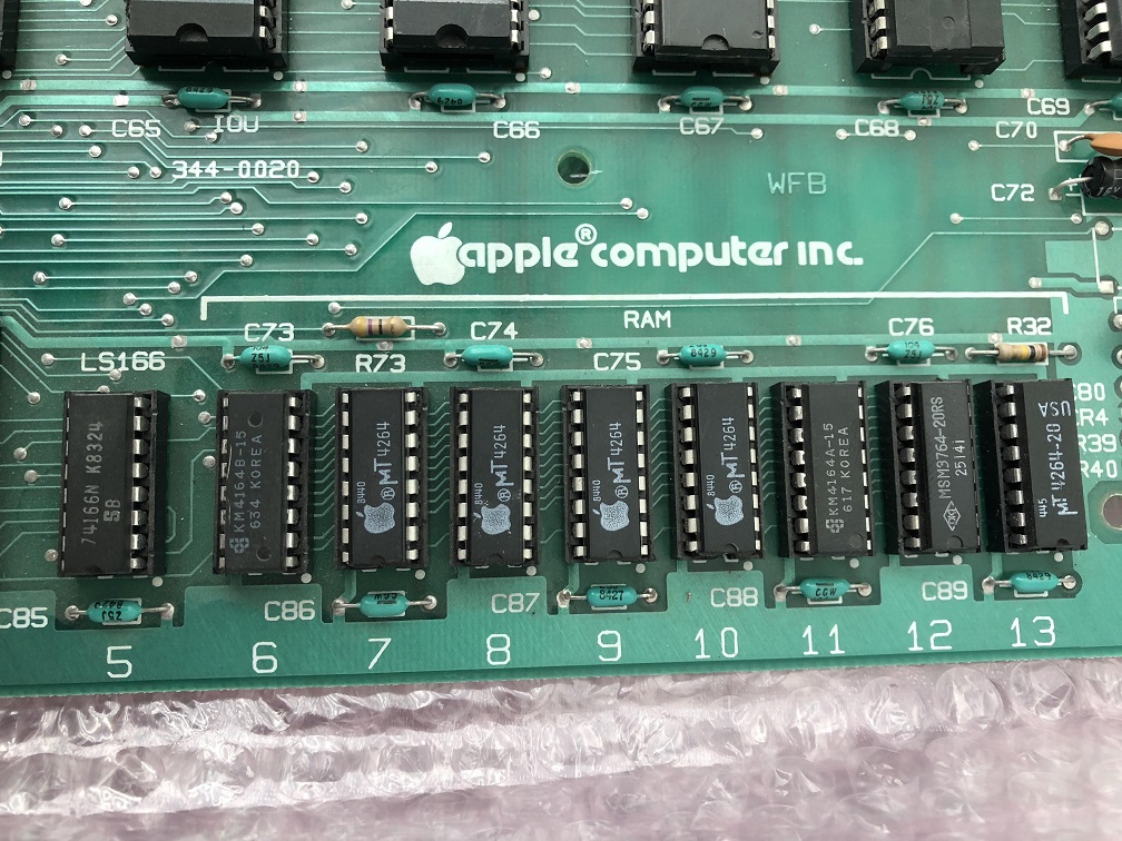
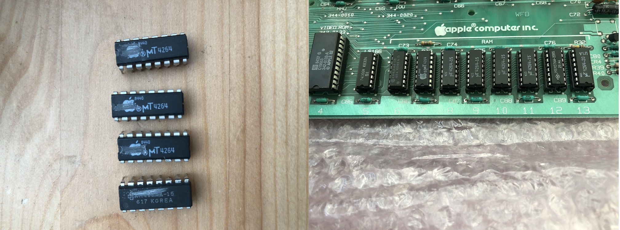
Taking one look at the RAM suggests there were issues in the past and most likely still issues. We have some original mT ( Micron ) / Apple branded DRAMs mixed in with the various replacements. Micron don’t exactly have the best reputation in regards to reliability so this is definitely a red flag. These were used by Commodore, Atari and obviously Apple as well. I guess they were cheap!
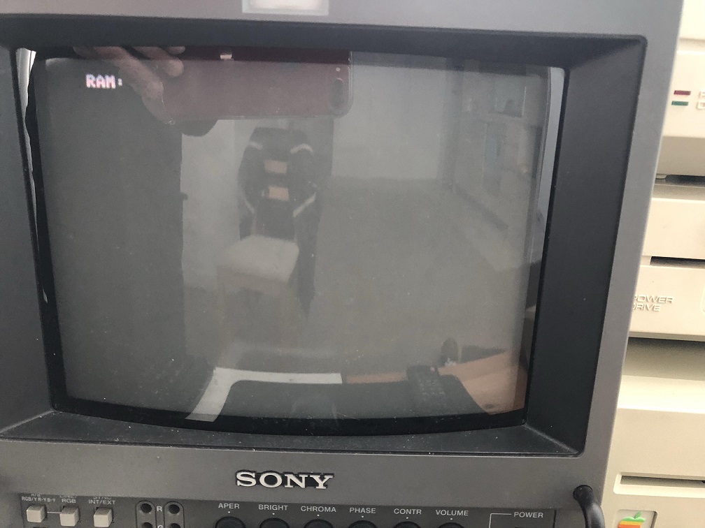
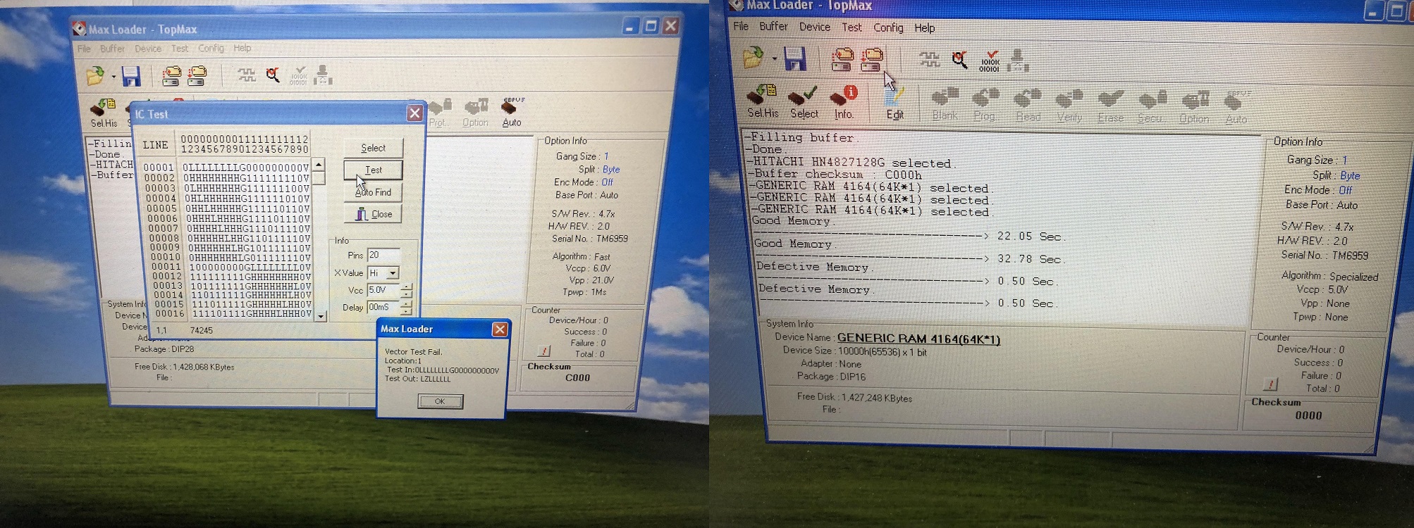
Based on the excellent condition of the board I was happy and confident in firing it up. It displays some kind of RAM error but it’s not very helpful, definitely not as helpful as the reporting in the Enhanced IIes built in diagnostic. I don’t have a choice but to go through and check each DRAM individually.
My TopMax helps me find 4 bad DRAMs of the 8. Three of which were Micron ( expected! ).
Dead RAM chips on the left clearly marked to remind me that these are dead and not to be mixed up with working. These will come in useful for refining my Atari 8bit diagnostic tool.
I temporarily replaced the dead RAM chips with known good Micron pulls from my friends Atari 800xl. But I do have some NOS TMS 150ns chips that will be going in shortly.
Replacing the RAM confirms the fix.
It’s nice to have a second board ready to go if I need it, and the fact that it’s a non enhanced board with everything socketed is a plus. I’ll be looking at converting this over to enhanced at some point via a enhancement kit which involves a 65C02 and newer roms for Apple IIc compatibility.
The final revision of the exported Apple IIe and Platinums use the International NTSC PCB, this ships with a very odd 50 hz NTSC configuration. The stock motherboard is fitted with a 14.238Mhz and requires the original 50hz Apple IIe Color Monitor to display a non monochrome picture on the screen. A standard 60hz capable NTSC monitor or 50hz PAL monitor ( as expected ) fails to pickup the colour on these machines due to some odd Hybrid combination.
Unfortunately my Apple Color monitor has a dead flyback and all efforts to source a replacement or substitute part went nowhere so I had to find an alternative. One alternative is using a PAL / Color encoder card but these are rare and expensive whenever they turn up.
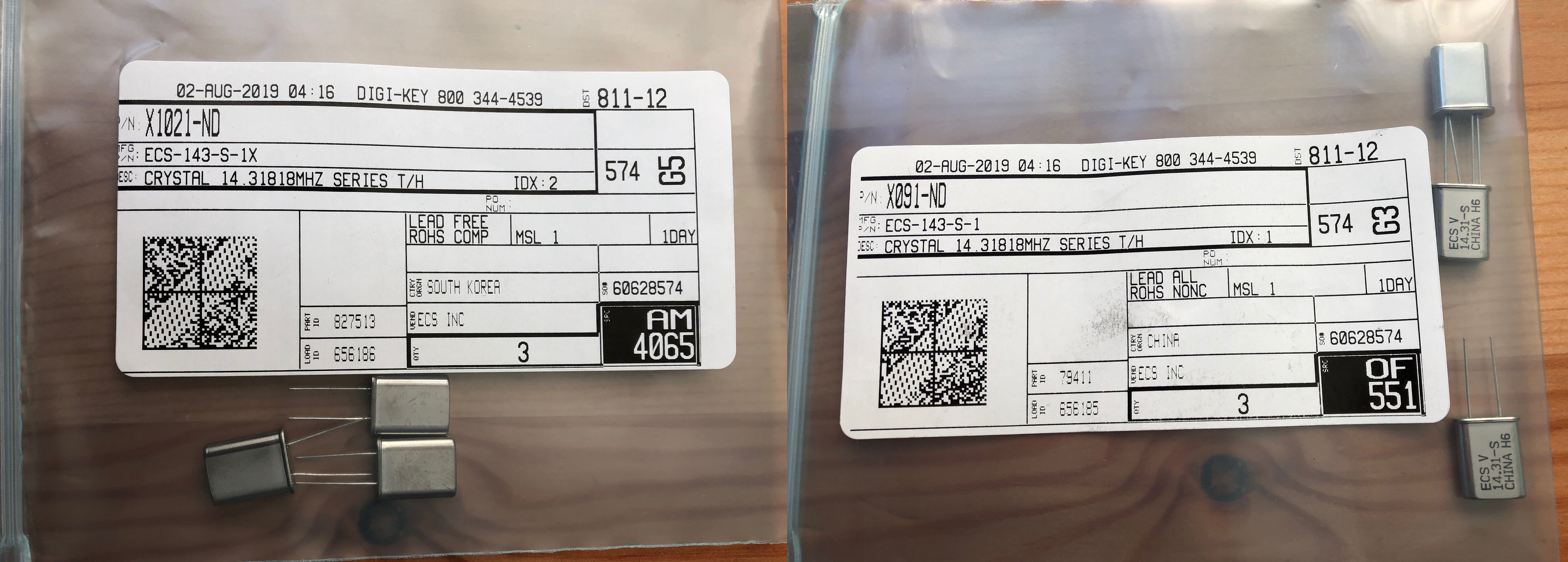
The theory to get colour involves changing the crystal at Y1 from 14.238Mhz to 14.31818MHz, this is logical and seems to work for most people who have tried this modification. One of the issues surrounding the crystal has already been discussed at length on the various forums, it must have an ESR of 25 ohms and not any off the shelf crystal will do apparently. Most people have had success using the specific type of crystal with the right characteristics, unfortunately I have not. After changing the crystal at Y1, I still had a black and white display on all my monitors ( Sony PVM, Philips & TEAC LCD ) which are capable of displaying 60hz NTSC in colour.
The PVM and my Commodore 1084s PAL monitor ( Philips made ) had no issues with locking on to sync despite the black and white monochrome picture ( expected in the 1084s case ). My Philips LCD still interpreted the signal as PAL even after changing the main crystal. In fact the signal was not stable and both LCDs were struggling to lock on to sync permanently, with the picture slightly shimmering or going completely out of sync for at least half a second ( as in the TEAC’s case ).
This has left me scratching my head as it appears that ALL my monitors were very picky , yet other people had success.
The Technical Reference Manual, in chapter 7 states that the IOU ( input / output unit ) handles and generates the video signals, video blanking, horizontal signals via some internal counters.
There are several different versions of the IOU but information out there is rather confusing and in some cases incorrect and that’s something I’d rather not cover at all. The NTSC International and even the PAL models use a very specific version of the IOU not found in the non export, U.S versions.
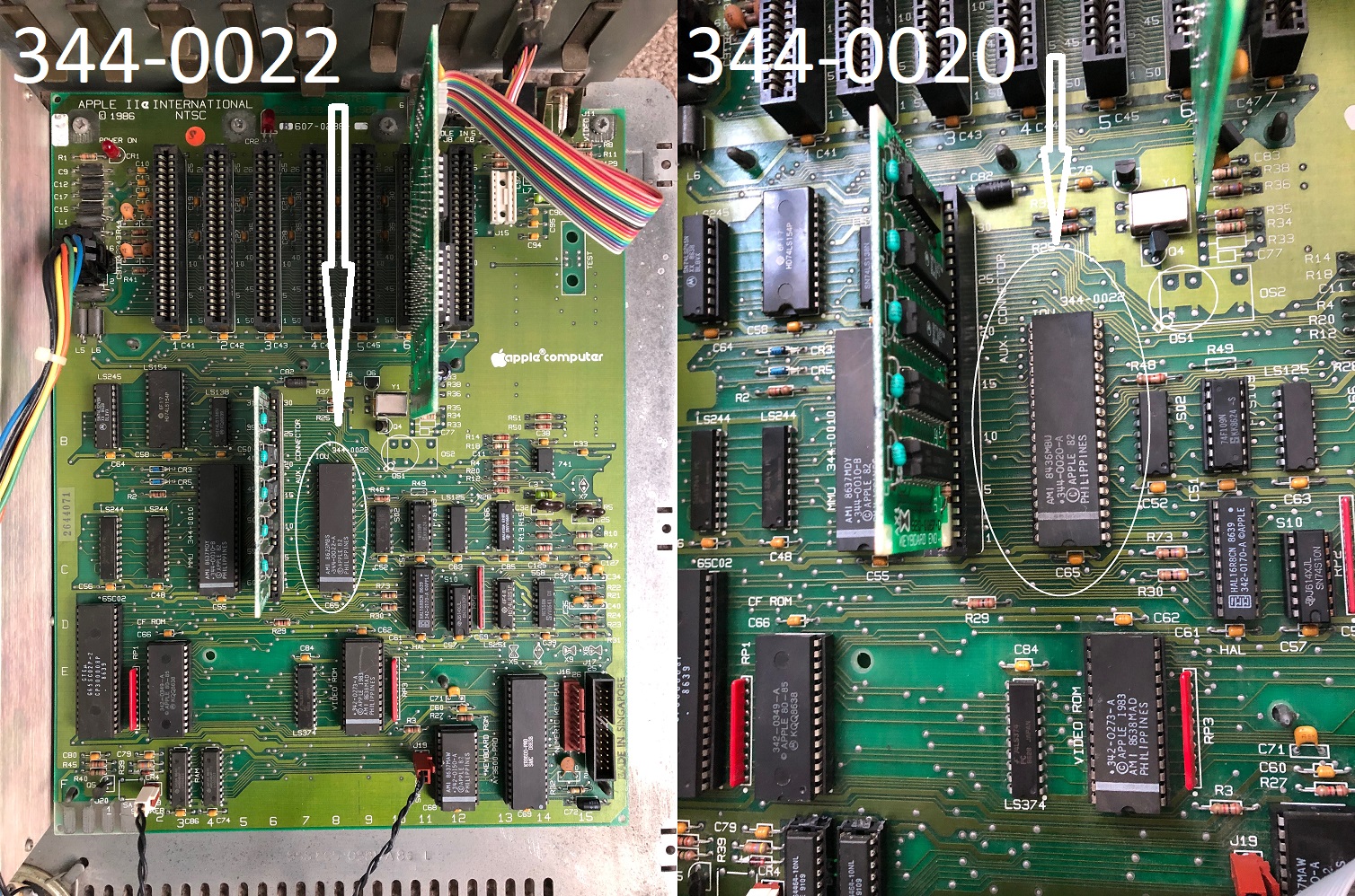
IOU 344-0022 ( used in International NTSC 50hz and PAL models ).
IOU 344-0020 ( NTSC 60hz ).
I had an idea to swap out the original 344-022 IOU for the 344-0020 and I took my chance on a non tested earlier IIe PCB. Thankfully only 4 RAM chips were bad ( mostly Micron, surprise surprise! ) which I’ll cover in my next repair log. I very carefully remove the original IOU, installed a machined pin socket and swapped the IOUs over. The original IOU still works in the other IIe after all that surgery ( Phew! ).
At some point later on I had to replace the RAM as well most likely caused by accidentally handling static prone devices without an anti-static wrist strap ( whoops! ). Not to worry, I have plenty of spares.
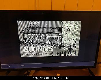
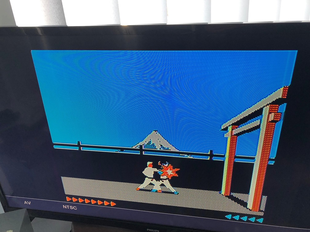
The results with splendid colour on my PVM!
And a valid NTSC signal on my Philips LCD ( Karateka in action! )
Conclusions: It was suggested the possibility that the original IOU was damaged or partially faulty ( I have to keep that in mind ) but I’ll never know unless someone else confirms the same or I can get my hands on another IOU ( 344-0022 ). I previously had the same exact issue in another IIe before I sold it, however I was using FOX143-20 branded crystals ( which have an ESR of 40 ohms ) at the time rather than the proven to work ones below which have an ESR of 25 ohms. I still have my FOX crystals on hand, so at some point I’d like explore those again and see if colour is still possible given I’ve swapped the IOU over to the 60hz version.
The following crystals have been proven to work. Still no colour on your International NTSC board ? Try a different IOU by substitution.
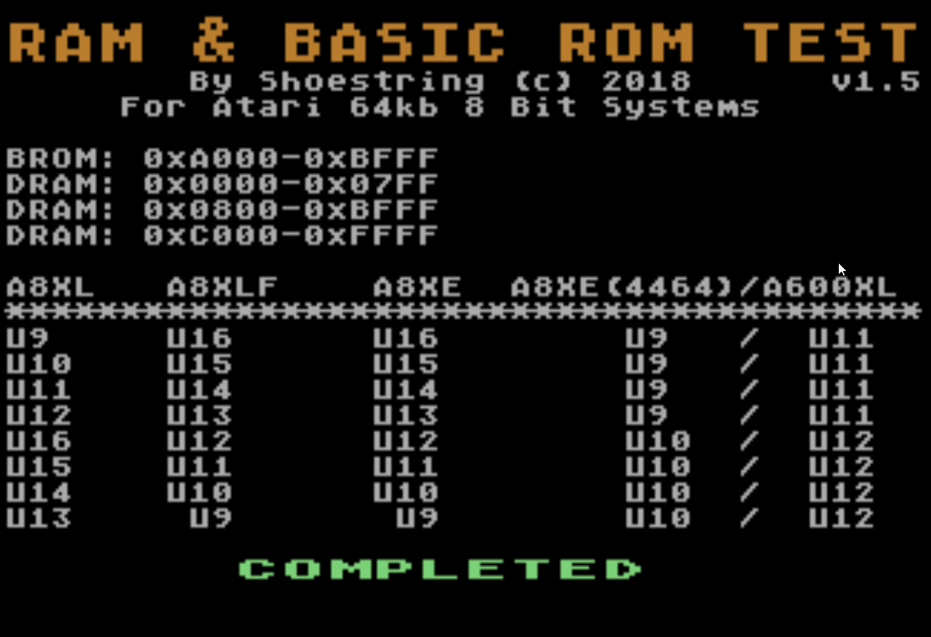
For Atari 800XL, 800XLF, 65XE and 600XL 64kb home computers.
Diagnostic program – previews
This program installs in the OS ROM socket and is used as a means for testing the DRAM and the Atari Basic ROM. If you have some spare 27c128s lying around then this can easily be installed without an adapter in any Atari 8 bit.
When the program first fires up you’ll see a black screen & hear an annoying sound as the data is being written to the first 2kb of DRAM, this is intentional and to let you know that the program is busy writing data and evaluating it. The first chunk of memory is critical to test as this contains page zero and work ram used for assembler programs accessing shadow registers..etc
Evaluates the first 2kb 0x0000 – 0x07ff.
Calculates a checksum of the BASIC ROM and stores the result in zero page if the memory there is good.
Turns off BASIC.
Performs evaluation from 0x800-0xbfff ( this includes the memory under the BASIC ).
Copies a large chunk of the ROM to DRAM starting at offset 0x900.
Turns off OS rom.
Tests the remainder of the memory 0xc000 – 0xffff, including the memory underneath the OS ROM but skipping the I/O area ( 0xd000-0xd7ff )
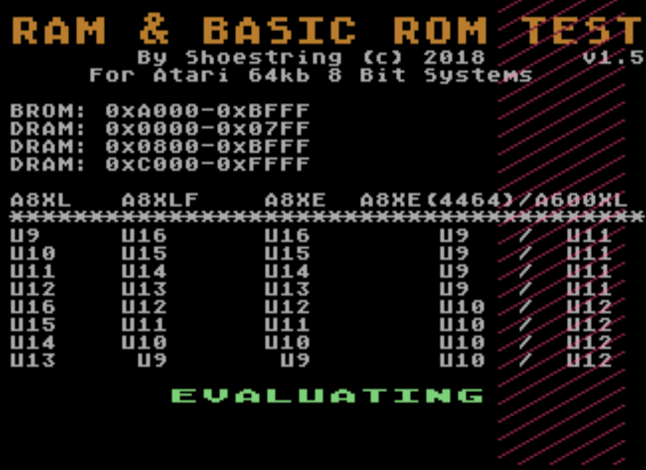
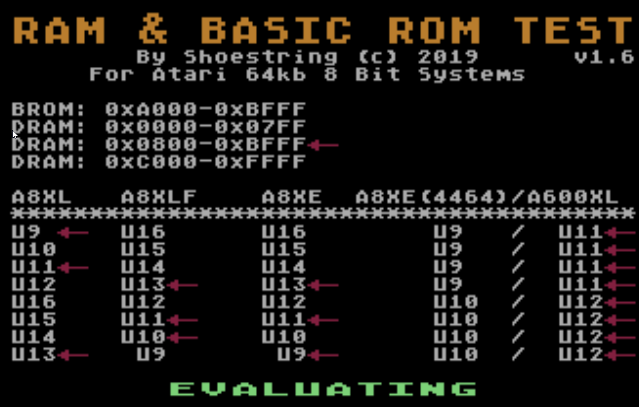
This writes the bit pattern directly to PMG address space which is visible on the right hand side of the screen in red.
Bad ram detected in the 0x800 to 0xBffff memory region ( the arrow indicates a bad data bit was read back )
What it does
During testing, the program displays bit patterns on screen which represent the data written to DRAM.
Plays sound to indicate CPU is functioning ( for systems playing blind ).
High beep = cleared one of the available algorithmic tests.
Low beep = successfully evaluated 100 memory locations with no errors during the exhaustive search.
Note: This does note evaluate the memory underneath the I/O ( 0xd000 – 0xd7ff ). As there is no possible way ( that I know of ) to access it like you can in the Commodore 64 via bank-switching. Programs do not utilise this area of memory anyway.
Pre calculated Basic ROM checksums 16 bit [ sum of bytes ]
REV A – 0x12c9
REV B – 0x4469
REV C – 0x42ab
Advantages of using the ROM
It will still boot up with no DRAM installed or with dead DRAM, as long as that is the only problem.
Great for testing completely dead systems with a black screen. If the system does not start then there are other hidden issues. If your system starts up fine with this ROM and there are no DRAM errors, suspect a bad OS ROM ( this would normally cause a red screen ).
Note – Chips that get hot to the touch including DRAM chips indicate an internal short. This should be addressed prior to using this diagnostic tool. +5 voltages below 4.75v will cause instability and unpredictable results. First remove the suspected chip from the machine then power the machine on and confirm no other chips are getting hot to the touch before installing the replacement chip, this is to prevent the possibility of damaging the replacement chip, confirm no short present by checking the +5v reading at one of the chips.
Do not use this diagnostic tool if you have not verified the operation of the power supply.
Limitations
PMG graphics are written to memory, so if bad ram is detected within these areas then expect unreliable results the wrong data bit being identified. By all means, any error detected should not indicate a false positive and you should manually test each DRAM chip externally using a RAM tester or device programmer that can handle these types of devices. I am currently further testing and investigating more reliable solutions.
To Do – In future version.
Wre-write the code regarding the reporting side of things and not totally rely on PMGs to indicate bad data bits. This will make reporting more accurate.
Write a 128kb version for 130XE machines.
What I probably won’t do
Write a version for systems with memory exceeding 128kb. The diagnostic was written as a means for trouble shooting a basic system.
This tool is compatible with the following DRAM configuration in the 600XL which requires two 4464s installed in the original sockets with 3 additional wires. See following link for instructions. If you use a 3rd party RAM expansion board, then chances are it will have 8 x 4164 1 bit DRAMs. Whilst you can certainly check the integrity of the RAM on the board using this program, you’ll most likely need to identify the bad chips yourself.